LLP-NTM1700WIRELESS STEREO AMPLIFIER
NASACO Electronics
Click to zoom
Application Details
- Equipment Class
- DSS - Part 15 Spread Spectrum Transmitter
- Date of Grant
- Oct 02, 2005
- Application Purpose
- Original Equipment
- Date of Application
- Oct 02, 2005
- Equipment Note
- WIRELESS STEREO AMPLIFIER
- Frequency Range
- 2403.33000000 - 2479.10000000
- Company
- NASACO Electronics
- Country
- Hong Kong
Documents & Files
Document Text
Text extracted from the exhibit documents filed with the FCC. Open a document above to read the original.
Users Manual
2.4GHz Digital Wireless Stereo Amplifier NTM1700 Page 1 Of 15 Rev 00 I. Location of Functions A. Transmitter (NTJD800) 1. Power On/Off 2. Power light 3. RCA/LINE IN select switch 4. RSSI light 5. VIDEO/AUDIO select switch 6. LINE IN jack 7. RCA jack 8. Charging jack 9. Power Input Jack 1 3 4 2 5 Front view 6 8 9 Rear view 7 Page 2 Of 15 Rev 00 B. Wireless Stereo Amplifier (NTM1700) 10. Power/RSSI light 11. Left Speaker Output 12. Right Speaker Output 13. Power Input Jack 14. ON/OFF switch 15. Volume knob 10 Front view Page 3 Of 15 Rev 00 15 14 13 12 11 Rear view Accessories: Audio Cable (3.5mm to 3.5mm Stereo) Page 4 Of 15 Rev 00 RCA to SPK Cable Y Cable (RCA to 3.5 Stereo Plug) Stereo Plug Adaptor (6.3 Plug to 3.5 Jack) Page 5 Of 15 Rev 00 Adaptor (6V 500mA) for Transmitter EPA-241DAN-15 Adaptor (15V 1600mA) for Wireless stereo Amplifier, Or Adaptor (15V 800mA) for Wireless Stereo Amplifier Page 6 Of 15 Rev 00 Or UL Adapter (Input: 120, 60Hz; Output: 17V, 1.1A), for Wireless Stereo Amplifier, Part no.: HA57U-560 Or HA57VF-1711, (Input 230Vac 50Hz, 120mA, Output: 17Vdc, 1.1A), for Wireless Stereo Amplifier, Page 7 Of 15 Rev 00 Connecting the System I. Powering the Transmitter Connect the small, round plug from the transmitter AC power adaptor to the transmitter power input jack and plug the other end of the adaptor into any standard 120V AC wall outlet. Page 8 Of 15 Rev 00 Press the ON/OFF button of the transmitter. The Red LED on the power light should be ON. II. Connecting to an Audio Source Connect the audio cable to the LINE IN jack of the transmitter and plug the other end to audio source (e.g. LINE OUT of DVD player). Turn the LINE IN selection switch to LINE IN. Page 9 Of 15 Rev 00 The Audio/Video Switch is for latency select. Usually set at Audio for music listening. III. Connecting to Speakers Page 10 Of 15 Rev 00 Insert bare wire part of speaker cables of to corresponding Left and Right Channel Output of the Wireless Amplifier. IV. Powering the Wireless Amplifier i. Turn the volume by rotating the volume control at the back of the unit to middle. ii. Insert the small, round plug from Wireless Amplifier AC power adaptor into the power input jack iii. Plug the other end of the AC power adaptor into any standard 120V AC wall outlet. Note: Be sure to use the AC power adaptors rated 15V DC 1600mA or listed in page 6, 7 and 8. 1. After powering up the Wireless Amplifier, the power/RSSI indicator will start blinking in green and orange color and searching for transmitter. Page 11 Of 15 Rev 00 2. If transmitter is found and connected, the power/RSSI indicator will turn green. 3. Turn volume up at the back and you should hear sound coming from the speakers. Adjust the volume as desired. V. Audio Muting When audio source is cut off for 3 minutes, the Wireless Amplifier will be muted. But if audio signal resumes, the muting will be disabled and speaker will be ON again. VI. Active/Passive Receivers The 2.4GHz system can support infinite no. of receivers (wireless amplifiers, speakers or headphones). However, the no. of receivers increase, the performance will be downgraded, i.e. transmission range will be reduced. The first two receivers paired with the transmitter are called “Active” receiver/speaker. The receivers paired later than the “Active” receiver/speakers are called “Passive” receiver/speaker. For multi-receiver system, the “Active” Page 12 Of 15 Rev 00 receivers/speakers can maintain its performance and are independent with the no. of receivers in the system. If one “Active” receiver/speaker is powered off, the other “Passive” receivers/speakers cannot be jumped into Active Mode automatically. They have to be powered off first and then power up again to make it “Active”. Page 13 Of 15 Rev 00 Page 14 Of 15 Rev 00 The antenna(s) used for this transmitter must be installed to provide a separation distance of at least 20 cm from all persons and must not be co-located or operating in conjunction with any other antenna or transmitter. Nasaco NTM-1700 This device complies with part 15 of the FCC rules. Operation is subject to the following two conditions: (1) This device may not cause harmful interference, and (2) this device mus t accept any interference received, including interference that may cause undesire d operation. TESTED TO COMPL Y WITH FCC STANDARDS FOR HOME OR OFFICE USE FCC ID LLP-NTM1700 END Page 15 Of 15 Rev 00
External Photos
EUT PHOTOGRAPHS FOR 2.4GHz DIGITAL WIRELESS STEREO AMPLIFIER Front View Rear View 56S050710 56S050710 EUT PHOTOGRAPHS FOR 2.4GHz DIGITAL WIRELESS STEREO AMPLIFIER Right View EUT PHOTOGRAPHS FOR 2.4GHz DIGITAL WIRELESS STEREO AMPLIFIER 56S050710 56S050710 Top View Bottom View 56S050710 56S050710
ID Label/Location Info
Labelling requirements per Section 2.925 & 15.19 The label shown will be permanently affixed at a conspicuous location on the device and be readily visible to the user at the time of purchase. Sample Label Physical Location of FCC Label on EUT
Internal Photos
EUT PHOTOGRAPHS FOR 2.4GHz DIGITAL WIRELESS STEREO AMPLIFIER Internal View 1 Internal View 2 56S050710 56S050710 EUT PHOTOGRAPHS FOR 2.4GHz DIGITAL WIRELESS STEREO AMPLIFIER EUT PCB Component Side (All PCBs) 56S050710 EUT PHOTOGRAPHS FOR 2.4GHz DIGITAL WIRELESS STEREO AMPLIFIER EUT PCB Trace Side (All PCBs) 56S050710 EUT PHOTOGRAPHS FOR 2.4GHz DIGITAL WIRELESS STEREO AMPLIFIER EUT PCB Component Side (Port & Connector Board) 56S050710 EUT PHOTOGRAPHS FOR 2.4GHz DIGITAL WIRELESS STEREO AMPLIFIER EUT PCB Trace Side (Port & Connector Board) 56S050710 EUT PHOTOGRAPHS FOR 2.4GHz DIGITAL WIRELESS STEREO AMPLIFIER EUT PCB Component Side (LED Board) 56S050710 EUT PHOTOGRAPHS FOR 2.4GHz DIGITAL WIRELESS STEREO AMPLIFIER EUT PCB Trace Side (LED Board) 56S050710 EUT PHOTOGRAPHS FOR 2.4GHz DIGITAL WIRELESS STEREO AMPLIFIER EUT PCB Component Side (Main RF Board) 56S050710 EUT PHOTOGRAPHS FOR 2.4GHz DIGITAL WIRELESS STEREO AMPLIFIER EUT PCB Trace Side (Main RF Board) EUT PHOTOGRAPHS FOR 2.4GHz DIGITAL WIRELESS STEREO AMPLIFIER 56S050710 RF Module Circuit with RF Shield RF Module Circuit with RF Shield Removed 56S050710 RF Module 56S050710
Operational Description
EUT OPERATING CONDITIONS FCC Part 15 1. Conducted Emissions 2. Radiated Emissions (Spurious Emissions inclusive Restricted Bands Requirement) 3. Spectrum Bandwidth (20dB Bandwidth Measurement) 4. Maximum Peak Power 5. RF Conducted Spurious Emissions 6. Peak Power Spectral Density 7. Maximum Permissible Exposure 8. Duty Cycle Factor Computation The EUT was exercised by operating in maximum continuous transmission with frequency hopping off, i.e transmitting at lower, middle and upper channels respectively at one time. FCC Part 15 1. Carrier Frequency Separation 2. Number of Hopping Frequencies 3. Average Frequency Dwell Time 4. Band Edge Compliance The EUT was exercised by operating in maximum continuous transmission with frequency hopping on.
Test Report
TEST REPORT Your Ref:Date: 2 Sep 2005 Our Ref: 56S050710/02 Page: 1 of 47 DID: +65-6885 1459 Fax: +65-6774 1459 NOTE: This report is issued subject to PSB Corporation's "Terms and Conditions Governing Technical Services". The terms and conditions governing the issue of this report are set out as attached within this report. LA-2001-0212-A LA-2001-0213-F LA-2001-0214-E LA-2001-0215-B LA-2001-0216-G LA-2001-0217-G The results reported herein have been performed in accordance with the laboratory’s terms of accreditation under the Singapore Accreditation Council - Singapore Laboratory Accreditation Scheme. Tests marked "Not SAC-SINGLAS Accredited" in this Report are not included in the SAC-SINGLAS Accreditation Schedule for our laboratory. Head Office: PSB Corporation • Testing Group • 1 Science Park Drive Singapore 118221 • Hotline:+65 6885 1333 • Fax:+65 6775 9725 • Email: [email protected] • Website: www.psbcorp. com Reg. No. : 199002667R • Regional Offices: Bangkok • Guangzhou • Jakarta • Kuala Lumpur • Qingdao • Shanghai • Tianjin FORMAL REPORT ON TESTING IN ACCORDANCE WITH FCC Parts 15B & C : 2005 OF A 2.4GHz DIGITAL WIRELESS STEREO AMPLIFIER [ Model : NTM-1700 ] [ FCC ID : LLP-NTM1700 ] TEST FACILITY Telecoms & EMC, Testing Group, PSB Corporation Pte Ltd 1 Science Park Drive, Singapore 118221 FCC REG. NO. 90937 (3m & 10m OATS) 99142 (10m Anechoic Chamber) 871638 (5m Anechoic Chamber) 325572 (10m Anechoic Chamber) IND. CANADA REG. NO. IC 4257 (10m Anechoic Chamber) PREPARED FOR Nasaco Electronics Pte Ltd 49 Changi South Avenue 2 Level 4, Nasaco Tech Centre Singapore 486056 Tel : +65 6214 0676Fax : +65 6214 1146 JOB NUMBER 56S050710 TEST PERIOD 22 Aug 2005 – 30 Aug 2005 PREPARED BYAPPROVED BY ____________________ Quek Keng Huat Associate Engineer ____________________ Lim Cher Hwee Product Manager 56S050710/02Nasaco Electronics Pte Ltd Page 2 of 47 2.4GHz Digital Wireless Stereo Amplifier [ Model : NTM-1700 ] [ FCC ID : LLP-NTM1700 ] TABLE OF CONTENTS TEST SUMMARY PRODUCT DESCRIPTION SUPPORTING EQUIPMENT DESCRIPTION EUT OPERATING CONDITIONS CONDUCTED EMISSION TEST RADIATED EMISSION TEST CARRIER FREQUENCY SEPARATION TEST SPECTRUM BANDWIDTH (20dB BANDWIDTH MEASUREMENT) TEST NUMBER OF HOPPING FREQUENCIES TEST AVERAGE FREQUENCY DWELL TIME TEST MAXIMUM PEAK POWER TEST RF CONDUCTED SPURIOUS EMISSIONS TEST BAND EDGE COMPLIANCE TEST PEAK POWER SPECTRAL DENSITY TEST MAXIMUM PERMISSIBLE EXPOSURE (MPE) TEST DUTY CYCLE FACTOR COMPUTATION ANNEX A- EUT PHOTOGRAPHS / DIAGRAMS ANNEX B- FCC LABEL & POSITION ANNEX C- USER MANUAL, TECHNICAL DESCRIPTION, BLOCK & CIRCUIT DIAGRAMS 56S050710/02Nasaco Electronics Pte Ltd Page 3 of 47 2.4GHz Digital Wireless Stereo Amplifier [ Model : NTM-1700 ] [ FCC ID : LLP-NTM1700 ] TEST SUMMARY The product was tested in accordance with the customer's specifications. Test Results Summary Test StandardDescriptionPass / Fail FCC Part 15: 2005 15.107(a), 15.207Conducted EmissionsPass 15.109(a), 15.205, 15.209 Radiated Emissions (Spurious Emissions inclusive Restricted Bands Requirement) Pass Carrier Frequency SeparationPass15.247(a)(1) Spectrum Bandwidth (20dB Bandwidth Measurement) Pass Number of Hopping FrequenciesPass15.247(a)(1)(iii) Average Frequency Dwell TimePass 15.247(b)(1)Maximum Peak PowerPass 15.247(d)RF Conducted Spurious EmissionsPass 15.247(d)Band Edge CompliancePass 15.247(e)Peak Power Spectral DensityPass 1.1310Maximum Permissible Exposure Pass 15.35(c)Duty Cycle Factor ComputationRefer to page 46 for details 56S050710/02Nasaco Electronics Pte Ltd Page 4 of 47 2.4GHz Digital Wireless Stereo Amplifier [ Model : NTM-1700 ] [ FCC ID : LLP-NTM1700 ] TEST SUMMARY Notes 1.Three channels as listed below, which respectively represent the lower, middle and upper channels of the equipment under test (EUT) were chosen and tested. For each channel, the EUT was configured to operate in the test mode. Transmit Channel Frequency (GHz) Channel 02.40333 Channel 72.44224 Channel 142.47910 The EUT contains total 15 channels. 2.All the measurements in section 15.247 were done based on conducted measurements. 3.The EUT is a Class B device when in non-transmitting state and meets the FCC Part15B Class B requirements. Modifications 1.No modifications were made. 56S050710/02Nasaco Electronics Pte Ltd Page 5 of 47 2.4GHz Digital Wireless Stereo Amplifier [ Model : NTM-1700 ] [ FCC ID : LLP-NTM1700 ] PRODUCT DESCRIPTION Description: The Equipment Under Test (EUT) is a 2.4GHz Digital Wireless Stereo Amplifier. Factory Address: Nasaco Electronics (Shenzhen) Ltd. 7/F, Phase 1, Hing Yick Industrial Estate, Fu Yong, Shenzhen City, Guangdong, China. Manufacturer: Nasaco Electronics (HK) Ltd RM 1106, Eastern Centre 1065 King’s Road Tel – 852 2563 0592 Fax – 852 2565 9613 Model Number: NTM-1700 FCC IDs: LLP-NTM1700 Serial Number: Nil Microprocessor: Refer To Manufacturer Operating / Transmitting Frequency : 2.40333GHz to 2.47910GHz Modulation: Gaussian Frequency Shift Keying (GFSK) Port / Connectors: 1 x DC In jack 2 x Audio In (L & R) Rated Input Power: 15V DC via 110VAC 60Hz AC/D adapter Accessories: Power Adapter – Model 48-15-800 Input 120V 60Hz, 19W Output 15V DC 800mA 12W Power Adapter – Model HA57U-560 Input 120V 60Hz, 25W Output 17V DC 1.1A Power Adapter – Model EPA-241DAN-15 Input 100 - 240V 50 - 60Hz Output 15V DC 1.6A 56S050710/02Nasaco Electronics Pte Ltd Page 6 of 47 2.4GHz Digital Wireless Stereo Amplifier [ Model : NTM-1700 ] [ FCC ID : LLP-NTM1700 ] SUPPORTING EQUIPMENT DESCRIPTION Equipment Description (Including Brand Name) Model, Serial & FCC ID NumberCable Description (List Length, Type & Purpose) M/N: NTJD-800 S/N: Nil Nasaco Wireless Transmitter FCC ID: LLP-NTJD800 1.80m unshielded power adapter cable 56S050710/02Nasaco Electronics Pte Ltd Page 7 of 47 2.4GHz Digital Wireless Stereo Amplifier [ Model : NTM-1700 ] [ FCC ID : LLP-NTM1700 ] EUT OPERATING CONDITIONS FCC Part 15 1. Conducted Emissions 2. Radiated Emissions (Spurious Emissions inclusive Restricted Bands Requir…
Text truncated - open the document above for the full version.
Test Report
RADIATED SPURIOUS EMISSIONS PLOTS Channel 1 (30MHz - 1GHz) Channel 1 (1GHz – 3GHz) RADIATED SPURIOUS EMISSIONS PLOTS Channel 1 (3GHz-6GHz) Channel 1 (6GHz-12GHz) RADIATED SPURIOUS EMISSIONS PLOTS Channel 1 (12GHz-18GHz) Channel 1 (18GHz-25GHz) RADIATED SPURIOUS EMISSIONS PLOTS Channel 7 (30MHz - 1GHz) Channel 7 (1GHz – 3GHz) RADIATED SPURIOUS EMISSIONS PLOTS Channel 7 (3GHz-6GHz) Channel 7 (6GHz-12GHz) RADIATED SPURIOUS EMISSIONS PLOTS Channel 7 (12GHz-18GHz) Channel 7 (18GHz-25GHz) RADIATED SPURIOUS EMISSIONS PLOTS Channel 14 (30MHz -1GHz) Channel 14 (1GHz-3GHz) RADIATED SPURIOUS EMISSIONS PLOTS Channel 14 (3GHz-6GHz) Channel 14 (6GHz-12GHz) RADIATED SPURIOUS EMISSIONS PLOTS Channel 14 (12GHz-18GHz) Channel 14 (18GHz-25GHz)
Test Setup Photos
CONDUCTED EMISSION TEST Conducted Emissions Test Setup (Front View) Conducted Emissions Test Setup (Rear View) RADIATED EMISSION TEST Radiated Emissions Test Setup (Front View) Radiated Emissions Test Setup (Rear View) Carrier Frequency Separation Test Setup Spectrum Bandwidth (20dB Bandwidth Measurement) Test Setup Number of Hopping Frequencies Test Setup Average Frequency Dwell Time Test Setup RF Conducted Spurious Emissions Test Setup Band Edge Compliance Test Setup Peak Power Spectral Density Test Setup Maximum Peak Power Test Setup MAXIMUM PERMISSIBLE EXPOSURE (MPE) TEST Maximum Permissible Exposure (MPE) Test Setup
Contact Information
Applicant
So Yan Kwan(Managing Director)
Test Firm
TUV SUD PSB Pte LtdHarold Tan
Technical Specifications
| # | Rule Parts | Frequency Range | Power Output |
|---|---|---|---|
| 1 | 15C | 2.40 GHz - 2.48 GHz | 38.00 mW |
Other Applications from NASACO Electronics

LLP-MGJ811S
Jun 12, 2007915 MHz Wireless Audio Transmitter
Equipment Class
DXX - Part 15 Low Power Communication Device Transmitter
LLP-NTE8100
Dec 10, 2006Bluetooth Headset
Equipment Class
DSS - Part 15 Spread Spectrum Transmitter
LLP-NTE4002
Sep 04, 2006Bluetooth Stereo Headset
Equipment Class
DSS - Part 15 Spread Spectrum Transmitter
LLP-NTE3100
Apr 24, 2006Bluetooth Neckband Stereo Headphones
Equipment Class
DSS - Part 15 Spread Spectrum Transmitter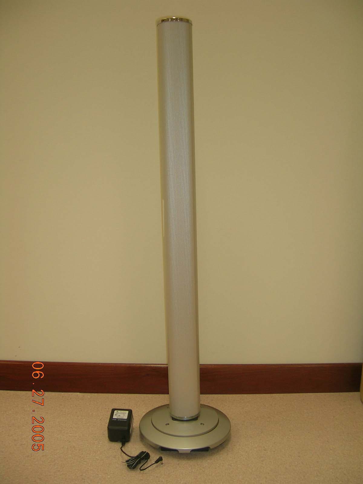
LLP-NTID800
Jul 10, 2005WIRELESS SPEAKER TRANSMITTER
Equipment Class
DSS - Part 15 Spread Spectrum Transmitter