Text extracted from the exhibit documents filed with the FCC. Open a document above to read the original.
TX: 433.92Mhz Two- way Communi- Shock Shock cation Unit Sensor 1 Sensor 2 Interface of Remote Interface Automobile output Starter of Automobile Control signal Module Input Signal Block Diagram of the Main Control Unit Main Control Unit
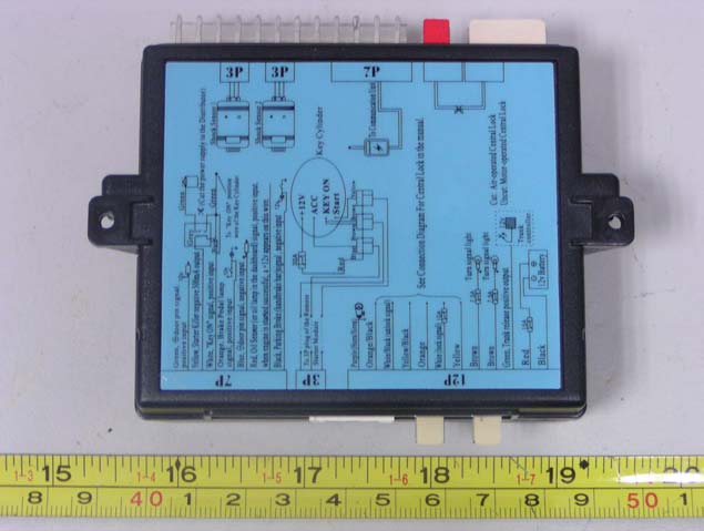
External Photos EUT -Base Front View EUT-Base Back View
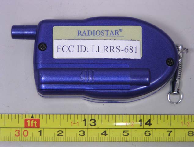
ID Label Label FCC ID: LLRRS-680
ID Label/Location Label Location Information Specifications: Text is Black or white in color and is left justified. Labels are printed in indelible ink on permanent adhesive backing or silk-screened onto the EUT or shall be affixed at a conspicuous location on the EUT. Refer to the below arrow.
Internal Photos FIGURE 1 EUT βBase Uncovered view EUT βBase PCB front view EUT -Base PCB back view
Circuit Description of the Main Control Unit RECEIVER The signal received by the antenna (ANT1) passes through the conversion circuit (D1,D2,R45,R2) and BAND PASS FILTER LC (C2, T1, C3) and is amplified at RF AMPLIFER.(Q1). The amplified signal is filtered by BAND PASS FILTER (C8,T2) to eliminate unwanted signal before passing through THE FIRST MIXER(Q2). The voltage of transfiguration diode is controlled by the pin25 of MCU . The signal supplied by RF AMPLIFIER mixed with the first local oscillator signal supplied by Crystal Frequency Multiple circuit (Q5) at THE FIRST MIXTER and generate THE FIRST IF SIGNAL of 21.4MHz. The FIRST IF SIGNAL passes through the crystal filter (FL1) to eliminate the spurious signals of adjacent channel. After being amplified by Q3, the 1ST IF signal enters into FM processing chip (U1). The signal remixed with the second local oscillator signal (20.945MHz) in the FM procession chip (U1), which generates the second IF Signal of 455Khz. The Second Local Oscillator Signal will pass through ceramic filter (FL2) for clearing the useless spurious signals before it is amplified and demodulated. The audio signal, discriminated by (TC/C32), is filtered by low past filter (C19, R15,R16,C20) and then shaped by FM processing chip(U1) to turn into FSK signal. Afterwards the FSK signal passes a pull-up resistor (R2) and goes to the pin12 of MCU for decoding. The MCU decodes the received FSK signal and takes the corresponding actions controlled by the Remote Control such as arming, disarming, checking, trunk releasing, starting ...etc by output high level driving signal to activate relays with a specified timing sequence. TRANSMITTER There are several detections from the signal of the vehicle as inputs to MCU. These signals include door, ignition, oil sensor, brake pedal, parking brake and shock sensor. The signal triggered by these detections or the ACK signal are from pin23 of MCU and pass through a low pass filter(R24,C36,R27,C35) and removes the portion higher than 3khz. The signal directly enters into the transfiguration diode (D5) of the Crystal Frequency Multiple circuit (Q5) to generate the FSK signal. Then the signal is buffered and amplified by Q6 following with a low pass filter and then is amplified with 14dbm power output by Q7. Before its arrival at the end of antenna, TX AMPLIFIER output signal passes through a Low Pass Filter network (C48,L9) and a RX/RX conversion circuit which consists of D2, R2 , D1 and L8. D1 is open under the mode of transmitting and close under the mode of receiving.
Note: This test report is specially limited to the above client company and the product model only. It may not be duplicated without prior written consent of Bay Area Compliance Laboratory Corporation. This report must not be used by the client to claim product endorsement by NVLAP or any agency of the U.S. Government. FCC PART 15 Subpart C EMI MEASUREMENT AND TEST REPORT For CHINA NATIONAL ELECTRONICS IMPORT& EXPORT SHENZHEN COMPANY 35/ F, BLOCK A, ELECTRONICS SCIENCE& TECHNOLOGY BUILDING, 2070, SHENNAN ZHONGLU, SHENZHEN, CHINA. FCC ID: LLRRS-680 July 2, 2003 This Report Concerns: Original Report Equipment Type: CAR ALARM SYSTEM Test Engineer: Jandy Su Report No.: RSZ03060903 Test Date: June 9, 2003 Reviewed By: Prepared By: Bay Area Compliance Lab Corp. Suite C, 41-D Electronics Science & Technology Building, No. 2070 Shennanzhong Rd ShenZhen, Guandong 518031, P.R. China Tel: (755) 83296449 Fax: (755) 83273756 CHINA NATIONAL ELECTRONICS IMPORT& EXPORT SHENZHEN COMPANY FCC ID: LLRRS-680 Report # RSZ03060903.doc Page 2 of 12 FCC Part 15 Subpart C Test Report TABLE OF CONTENTS 1 - GENERAL INFORMATION..................................................................................................................................3 1.1 PRODUCT DESCRIPTION FOR EQUIPMENT UNDER TEST (EUT) ..............................................................................3 1.2 OBJECTIVE.............................................................................................................................................................3 1.3 RELATED SUBMITTAL(S)/GRANT(S) ......................................................................................................................3 1.4 TEST METHODOLOGY............................................................................................................................................3 1.5 TEST FACILITY.......................................................................................................................................................3 1.6 TEST EQUIPMENT LIST...........................................................................................................................................4 2 - SYSTEM TEST CONFIGURATION.....................................................................................................................5 2.1 DESCRIPTION OF TEST CONFIGURATION................................................................................................................5 2.2 CONFIGURATION OF TEST SYSTEM.........................................................................................................................5 2.3 TEST SETUP BLOCK DIAGRAM...............................................................................................................................5 2.4 EQUIPMENT MODIFICATIONS.................................................................................................................................5 3 - SUMMARY OF TEST RESULTS..........................................................................................................................6 4 - CONDUCTED EMISSIONS TEST DATA............................................................................................................7 5 - RADIATED EMISSION DATA .............................................................................................................................8 5.1 MEASUREMENT UNCERTAINTY..............................................................................................................................8 5.2 EUT SETUP............................................................................................................................................................8 5.3 SPECTRUM ANALYZER SETUP................................................................................................................................8 5.4 TEST PROCEDURE..................................................................................................................................................9 5.5 CORRECTED AMPLITUDE & MARGIN CALCULATION.............................................................................................9 5.6 SUMMARY OF TEST RESULTS.................................................................................................................................9 5.7 RADIATED EMISSIONS TEST RESULT DATA...........................................................................................................9 6 β OPERATION TIMES ...........................................................................................................................................10 6.1 TEST RESULTS.....................................................................................................................................................10 7 β BANDWIDTH TESTING .....................................................................................................................................11 7.1 TEST RESULTS.....................................................................................................................................................11 CHINA NATIONAL ELECTRONICS IMPORT& EXPORT SHENZHEN COMPANY FCC ID: LLRRS-680 Report # RSZ03060903.doc Page 3 of 12 FCC Part 15 Subpart C Test Report 1 - GENERAL INFORMATION 1.1 Product Description for Equipment Under Test (EUT) The CHINA NATIONAL ELECTRONICS IMPORT& EXPORT SHENZHEN COMPANYβs product, model name: RS-680 or the "EUT" as referred to in this report is CAR ALARM SYSTEM. The EUT is a Base Transmitter, which measures approximately 10.3cmL x 8.5cmW x 3.0cmH, Alarm Speaker measures approximately 8.0cmL x 8.0cmW x 9.0cmH. The EUT power: DC 12V battery, the battery was fresh charged before test. * The test data was good for test sample only. It may have deviation for other product samples. 1.2 Objective This document is a test report based on the Electromagnetic Interference (EMI) tests performed on the EUT. Thβ¦
Text truncated - open the document above for the full version.
Test Setup Photos Test Setup Photos Radiated Emission β Front View Radiated Emission β Rear View
| # | Rule Parts | Frequency Range | Power Output |
|---|---|---|---|
| 1 | 15C | 433.92 MHz - 433.92 MHz | - |

Car Alarm System
Equipment Class
DXX - Part 15 Low Power Communication Device Transmitter