LOM973SRTank level measuring gauge
Honeywell Enraf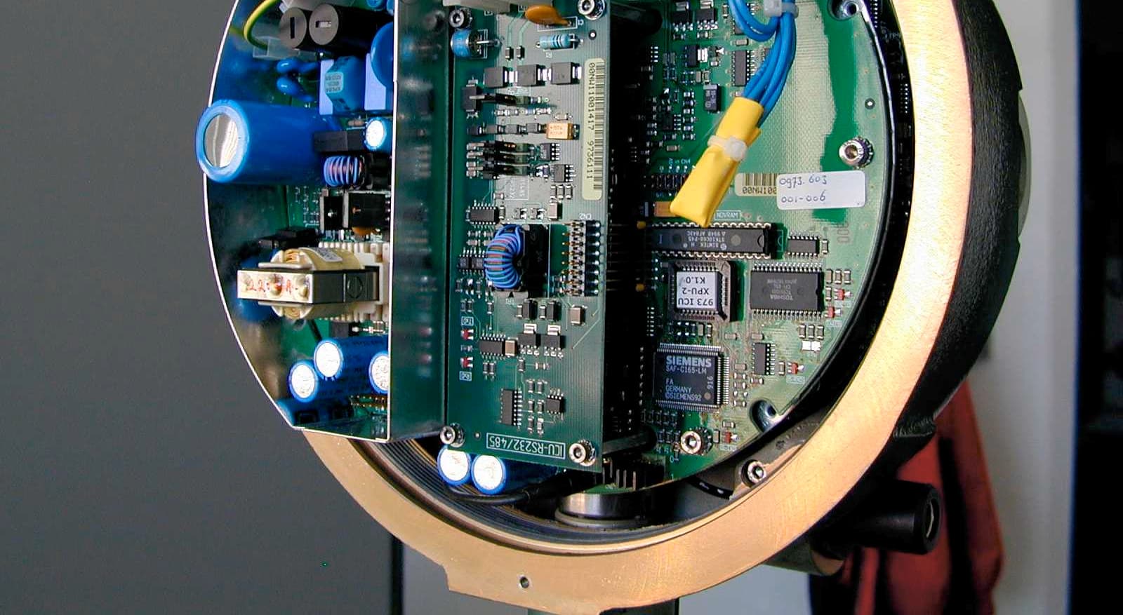
Click to zoom
Application Details
- Equipment Class
- FDS - Part 15 Field Disturbance Sensor
- Date of Grant
- Jul 02, 2002
- Application Purpose
- Original Equipment
- Date of Application
- May 12, 2002
- Equipment Note
- Tank level measuring gauge
- Frequency Range
- 9400.00000000 - 10700.00000000
- Company
- Honeywell Enraf
- Country
- Netherlands
Documents & Files
Document Text
Text extracted from the exhibit documents filed with the FCC. Open a document above to read the original.
Users Manual
Instruction manual 973 SmartRadar LT Page 1 Instruction manual 973 SmartRadar LT Version: 1.1 February 2002 Part no.: 4416.632_Rev 0 Enraf B.V. P.O. Box 812 2600 AV Delft Netherlands Tel.: +31 15 2698600, Fax: +31 15 2619574 E-mail: [email protected] http://www.enraf.com Page 2 Copyright 2000 Enraf B.V. All rights reserved. Reproduction in any form without the prior consent of Enraf B.V. is not allowed. This manual is for information only. The contents, descriptions and specifications are subject to change without notice. Enraf B.V. accepts no responsibility for any errors that may appear in this manual. The warranty terms and conditions for Enraf products applicable in the country of purchase are available from your supplier. Please retain them with your proof of purchase. Preface Instruction manual 973 SmartRadar LT Page 3 Preface This manual is intended for technicians involved in the commissioning and service of the Enraf series 973 SmartRadar LT gauge. A description preceding the technical procedures gives the technical information necessary to understand its functioning. It is recommended to read this description prior to performing any of the procedures. For installation of the 973 SmartRadar LT, please refer to the Installation guides of the 973 SmartRadar LT and SmartRadar Antennas. This manual describes the commissioning and service of the basic 973 SmartRadar LT level measurement. Other features such as level alarm output contact, verification pin compensation, temperature measurement (spot or average), analog level output and pressure measurement are described in separate manuals. For an overview, refer to the list of related documents in appendix D. Legal aspects The commissioning of and troubleshooting to the instrument may only be conducted by qualified engineers, trained by Enraf and with knowledge of safety regulations for working in hazardous areas. The information in this manual is the copyright property of Enraf B.V., Netherlands. Enraf B.V. disclaims any responsibility for personal injury or damage to equipment caused by: • Deviation from any of the prescribed procedures • Execution of activities that are not prescribed • Neglect of the safety regulations for handling tools and use of electricity EC declaration of conformity This instrument is in conformity with the protection requirements of EC Council Directive 93/68/EEC. The CE conformity marking fulfills the provision of: • 89/336/EEC regarding EMC: EN 50081-2 Generic Emission Standard EN 50082-2 Generic Immunity Standard • 73/23/EEC regarding Low Voltage Directive • 94/09/EEC regarding ATEX • 97/23/EEC regarding PED Directive Additional information Please do not hesitate to contact Enraf or its representative if you require any additional information. Table of contents Page 4 Table of contents Preface...........................................................................3 1Introduction........................................................................6 1.1Principle of measurement.......................................................6 1.2Configurations................................................................7 1.3Optional functions.............................................................9 1.4Remote monitoring............................................................9 1.5Approvals (FM, Cenelec)........................................................9 2Safety...........................................................................10 2.1Safety aspects of the 973 SmartRadar LT.........................................10 2.2Personal safety..............................................................10 2.3Safety conventions...........................................................11 3Commissioning....................................................................12 3.1Checks before starting the commissioning.........................................12 3.2Introduction in programming the 973 SmartRadar LT.................................12 3.3Connection of service tool Ensite................................................14 3.3.1Communication via the Enraf field bus line.................................14 3.3.2Communication via RS-232C or RS-485...................................15 3.3.3Communication via HART signal........................................15 ® 3.3.4Programming communication parameters..................................16 3.4Programming the gauge.......................................................18 3.4.1Selecting dimension and decimal separator................................19 3.4.2Level start-up........................................................20 3.4.3Level check..........................................................22 3.4.4Zones and threshold settings............................................23 3.4.5Alarm settings........................................................29 3.4.6Ullage readout.......................................................30 3.4.7Password protection...................................................31 3.4.8Detection algorithm and special settings...................................31 3.4.9Additional adjustment with measurement on stilling well.......................34 3.5Data items..................................................................36 4Service and troubleshooting..........................................................37 4.1SmartRadar LT layout.........................................................37 4.2The instrument covers.........................................................38 4.3Min max diagram.............................................................38 4.4Alarm loop checking..........................................................39 4.5Error codes and status information...............................................40 4.5.1XPU-2 error code (item EP) of ICU board..................................40 4.5.2APU warning code (item WC), error code (item EE) and status request (item QR) of ICU board............................…
Text truncated - open the document above for the full version.
Cover Letter(s)
TRP/Cetecom bvba May 13, 2002 Federal Communications Commission 7435 Oakland Mills Rd Columbia, MD 21036 Re: FCCID:LOM973SR Gentlemen: Submitted herewith is an application for a swept FM signal tank level radar gauge operating as a field disturbance sensor. This gauge is intended to be installed in metal tanks only and was tested in a simulated metal tank consisting of a closed end stilling well arrangement. Various antenna arrangements are provided depending on the application. The antenna configurations were investigated and a representative antenna measured, since none produced measurable emissions outside the metal tank. The signal is swept from 9.4 to 10.7 GHz. Sincerely, Phillip Inglis Consultant 14085 Howard Rd Dayton, MD 21036
Cover Letter(s)
TRP/Cetecom bvba April 15, 2002 Federal Communications Commission 7435 Oakland Mills Rd Columbia, MD 21036 Re: FCC ID:LOM973SR Gentlemen: Pursuant to Section 0.459 of the FCC Rules, Enraf request post grant confidentiality for the following items submitted as attachments to the application for certification for the reference FCC ID: 1. Schematic diagrams 2. Block diagram 3. Technical description. Sincerely, Phillip Inglis Consultant 14085 Howard Rd Dayton, MD 21036
Cover Letter(s)
FEDERAL COMMUNICATIONS COMMISSION WASHINGTON, D.C. 20554 GRANT OF EQUIPMENT AUTHORIZATION Certification Enraf BV Rontgenweg 1 2624 BD Delft, NL Date of Grant: 06/25/1996 Application Dated: 08/31/1995 Attention: G. C. Ginkel NOT TRANSFERABLE EQUIPMENT AUTHORIZATION is hereby issued to the named GRANTEE, and is VALID ONLY for the equipment identified hereon for use under the Commission's Rules and Regulations listed below. FCC IDENTIFIER LOM873SR Name of Grantee Enraf BV Equipment Cl ass: Part 15 Field Disturbance Sensor Notes: The referenced equipment is only authorized for use in the following applications: 1. Closed metal tanks with or without stilling wells. 2. External floating roof tanks with stilling wells. Grant Notes FCC Rule Parts Frequency Range (MHZ) Output Watts Frequency Tolerance Emission Designator 37 159500 - 10500 % 37: This device has shown compliance with new rules adopted under Docket 87-389 and is not affected by Section 15.37, transition rule. Mail To: <TD 9509148315619002
External Photos
CETECOM ICT Services GmbH Test report No.: 2-2422-A/01Date : 26.07.2001Page 23 of 27 4PhotosofEUT CETECOM ICT Services GmbH Test report No.: 2-2422-A/01Date : 26.07.2001Page 24 of 27
ID Label/Location Info
FCC ID Label and location: The following FCC ID will be placed on the back side of the equipment housing that is above the metallic tank the equipment is mounted on. FCC ID:LOM973SR Location: Back Side of Eqpt.
Internal Photos
F. Optional Board HART 4 – 20 mA G. 973 SmartRadar (without cover) D. Board GPS E. Option Board RS 232C/RS 458 I SmartRadar 973 Interior C. Option Board HPI Hart1, Hart 2, and Spot option III Equipment and Module Photographs A. Board ICU Option TSI communication III Equipment and Module Photographs A. Board ICU Option TSI communication B. Board RF2 DAB VCO H. 973 SmartRadar Interior
Test Report
CETECOM ICT Services GmbH Radio Satellite Communication Untertürkheimer Straße 6–10 , D-66117 Saarbrücken , Telefon +49 (0)681 598–0 , Fax –9075 Test report No.: 2-2422-A/01This test report consists of 27 pagesPage 1 of 27 Accredited Testing Laboratory DAR–Registration Number TTI–P–G 166/98 Test report No. : 2-2422-A/01 Customer :Enraf B.V. Product :973 SmartRadar LT CETECOM ICT Services GmbH Test report No.: 2-2422-A/01Date : 26.07.2001Page 2 of 27 Tableofcontents 1General information....................................................................................................................3 1.1 Notes .............................................................................................................................................3 1.2 Testing laboratory..........................................................................................................................4 1.3 Details of applicant........................................................................................................................4 1.4 Application details ........................................................................................................................4 1.5 Test item (EUT) ............................................................................................................................5 1.5.1 Operation conditions.................................................................................................................................. 5 1.5.2 Equipment under test ................................................................................................................................. 5 1.6 Test standards................................................................................................................................6 2Technical test...............................................................................................................................7 2.1 Summary of test results.................................................................................................................7 2.2 Test environment...........................................................................................................................7 2.3 Measurement and test set-up.........................................................................................................7 2.4 Test equipment utilized and test set-up.........................................................................................8 2.4.1 Radiated power and spurious radiation in the frequency range 4 GHz to 33 GHz (1. – 3. Harmonic)... 8 2.4.2 Radiated power and spurious radiation in the frequency range 33 GHz to 50 GHz (4. Harmonic).......... 9 2.4.3 Spurious radiation in the frequency range up to 4 GHz. ......................................................................... 10 2.5 Test results ..................................................................................................................................11 2.5.1 Test results overview............................................................................................................................... 11 3Plots ............................................................................................................................................19 4Photos of EUT............................................................................................................................23 5Test results and calculation for FCC requirements...............................................................26 CETECOM ICT Services GmbH Test report No.: 2-2422-A/01Date : 26.07.2001Page 3 of 27 1 General information 1.1 Notes The test results of this test report relate exclusively to the test item specified in 1.5 . CETECOM ICT Services GmbH does not assume responsibility for any conclusions and generalisations drawn from the test results with regard to other specimens or samples of the type of the equipment represented by the test item. The test report may only be reproduced or published in full. Reproduction or publication of extracts from the report requires the prior written approval of the CETECOM ICT Services GmbH. Tester : 01. Aug 2001Arno Dejon DateNameSignature Technical responsibility for area of testing : 01. Aug 2001Klaus Kammerinke DateNameSignature CETECOM ICT Services GmbH Test report No.: 2-2422-A/01Date : 26.07.2001Page 4 of 27 1.2 Testing laboratory CETECOM ICT Services GmbH Untertürkheimerstraße 6–10P.O. – Box 10 04 45 66117 Saarbrücken66004 Saarbrücken GermanyGermany Telefon : +49 (0)681 598–0 Telefax : +49 (0)681 598–9075 Accredited testing laboratory DAR-registration number:TTI-P-G 166/98 Testing location, if different from CETECOM ICT Services GmbH: Name: Street: Town: Country : Telephone : Fax: 1.3 Details of applicant Name: Enraf B.V. Street: Roentgenweg 1 Town: 2624 BD Delft Country : The Netherlands Telephone : +31 15 2698 600 Fax: +31 15 2618 061 Contact person Name: G.C. van Ginkel Telephone : +31 15 2698 333 Fax: +31 15 2618 061 E-Mail: [email protected] 1.4 Application details Date of receipt of application : 15.02.2001 Date of receipt of test item : 14.03.2001 Date of test: 14.03.2001 CETECOM ICT Services GmbH Test report No.: 2-2422-A/01Date : 26.07.2001Page 5 of 27 1.5 Test item (EUT) Description of EUT :Level gauge Product name:Radar Level Gauge Type name of product :973 SmartRadar LT Manufacturer:Enraf B.V. :Roentgenweg 1 :2624 BD Delft :The Netherlands Technical data Frequency range:9.4 GHz ... 10.7 GHz EIRP PEP:51.3 mW (17.1 dBm) Type of modulation :1G30F1N (FM CW) Microwave modules :TX / RX – Module Antennas:Planar antenna (tested), horn antenna, rod antenna Normal power supply :230 V AC Extreme power supply :85 ... 264 V AC 1.5.1 Operation conditions Operation::As soon as the equipment is powered up, TX and RX start operating Purpose of operation :Radar level gauge for operation in metal tanks 1.5.2 Equipment under test ENRAF Model 973 SmartR…
Text truncated - open the document above for the full version.
Test Setup Photos
CETECOM ICT Services GmbH Test report No.: 2-2422-A/01Date : 26.07.2001Page 10 of 27 Anechoic chamber 2.4.3 Spurious radiation in the frequency range up to 4 GHz. Test equipmentManufacturerTypeS/No.Calibration due Spectrum analyserHPHP 85660B 2478A0530605.07.2001 Analyser displayHPHP 85662A 2816A1654105.07.2001 Quasi peak adapterHPHP 85650A 2811A0113105.07.2001 RF-preselectorHPHP 85685A 2833A0076805.07.2001 Biconical antennaEmco3104375801.07.2001 Log.-per.-antennaEmco3146230401.07.2001 Double ridge hornEmco3115300701.07.2001 Relay switchR&SRSU375 339/00201.07.2001 High pass filterFSY Microwave HM 985955 00101.07.2001 AmplifierTron-TechP42-GA29 B230201.07.2001 Power supplyHPHP 6038A 2848A0702712.12.2001 RF-cableHP5061-5359 P3630312.12.2001 Measurement uncertainty Test parameterMeasurement uncertainty Power supply ±0.1 VAC Temperature ±0.2°C Frequency ±0.01 ppm eirp ±1.0 dB Test equipment d=5m HP EMC Set-up Turn table EUT
Contact Information
Applicant
Jan Bok(Approvals Engineer)
Technical Contact
TRP/Cetecom bvbaPhillip Inglis
[email protected]410 531 3439
14085 Howard Rd · Dayton, Maryland · United States
Non-Technical Contact
TRP/Cetecom bvbaPhillip Inglis
[email protected]410 531 3439
Test Firm
Cetecom ICT Services GmbHRalf Hoehn
Technical Specifications
| # | Rule Parts | Frequency Range | Power Output |
|---|---|---|---|
| 1 | 15C | 9.40 GHz - 10.70 GHz | - |
Other Applications from Honeywell Enraf
LOM978WFI
Apr 28, 2014Wireless Field Interface
Equipment Class
DTS - Digital Transmission System
LOM990SRFL-2
Jan 29, 2013Radar Level Tank Gauge
Equipment Class
JBP - Part 15 Class B Computing Device Peripheral
LOM990SRFL
Nov 06, 2007Radar Level Tank Gauge
Equipment Class
DXX - Part 15 Low Power Communication Device TransmitterLOM873SR
Jun 24, 1996The referenced equipment is only authorized for use in the following applications: 1. Closed metal tanks with or without stilling wells. 2. External floating roof tanks with stilling wells.
Equipment Class
FDS - Part 15 Field Disturbance Sensor