LOZ102038Direct Sequence Spread Spectrum Data Transceiver
Aironet Wireless Communications Inc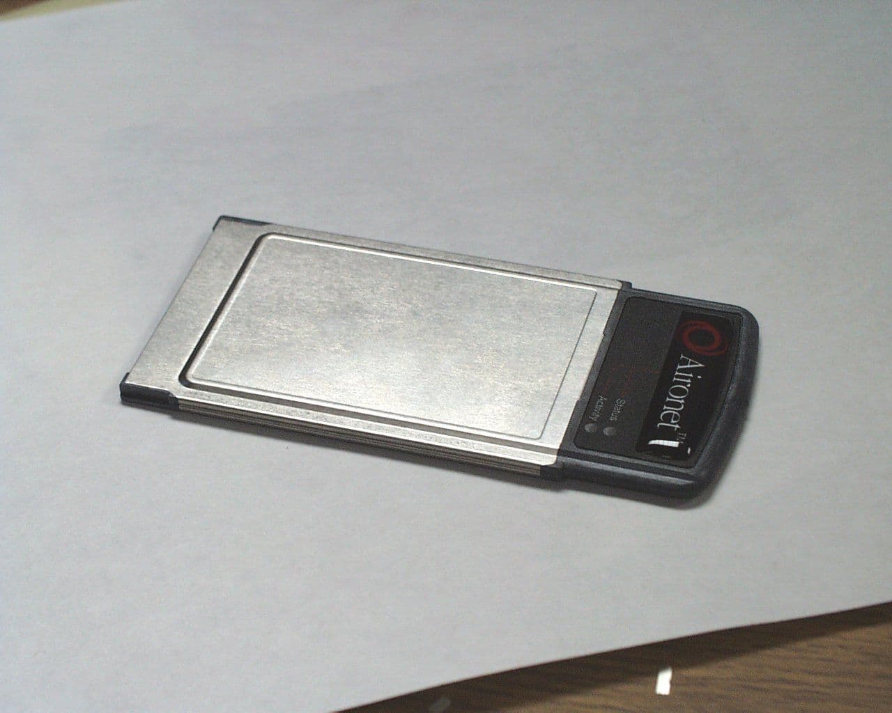
Click to zoom
Application Details
- Equipment Class
- DSS - Part 15 Spread Spectrum Transmitter
- Date of Grant
- Nov 14, 1999
- Application Purpose
- Original Equipment
- Date of Application
- Jul 22, 1999
- Equipment Note
- Direct Sequence Spread Spectrum Data Transceiver
- Frequency Range
- 2412.00000000 - 2462.00000000
- Country
- United States
Documents & Files
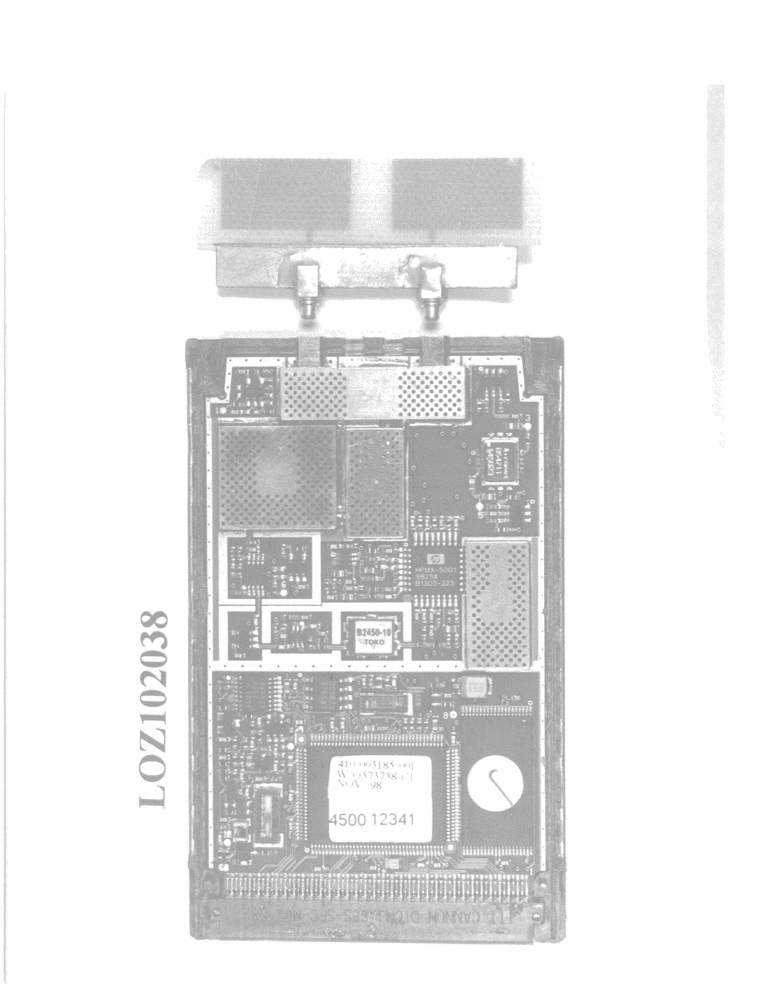
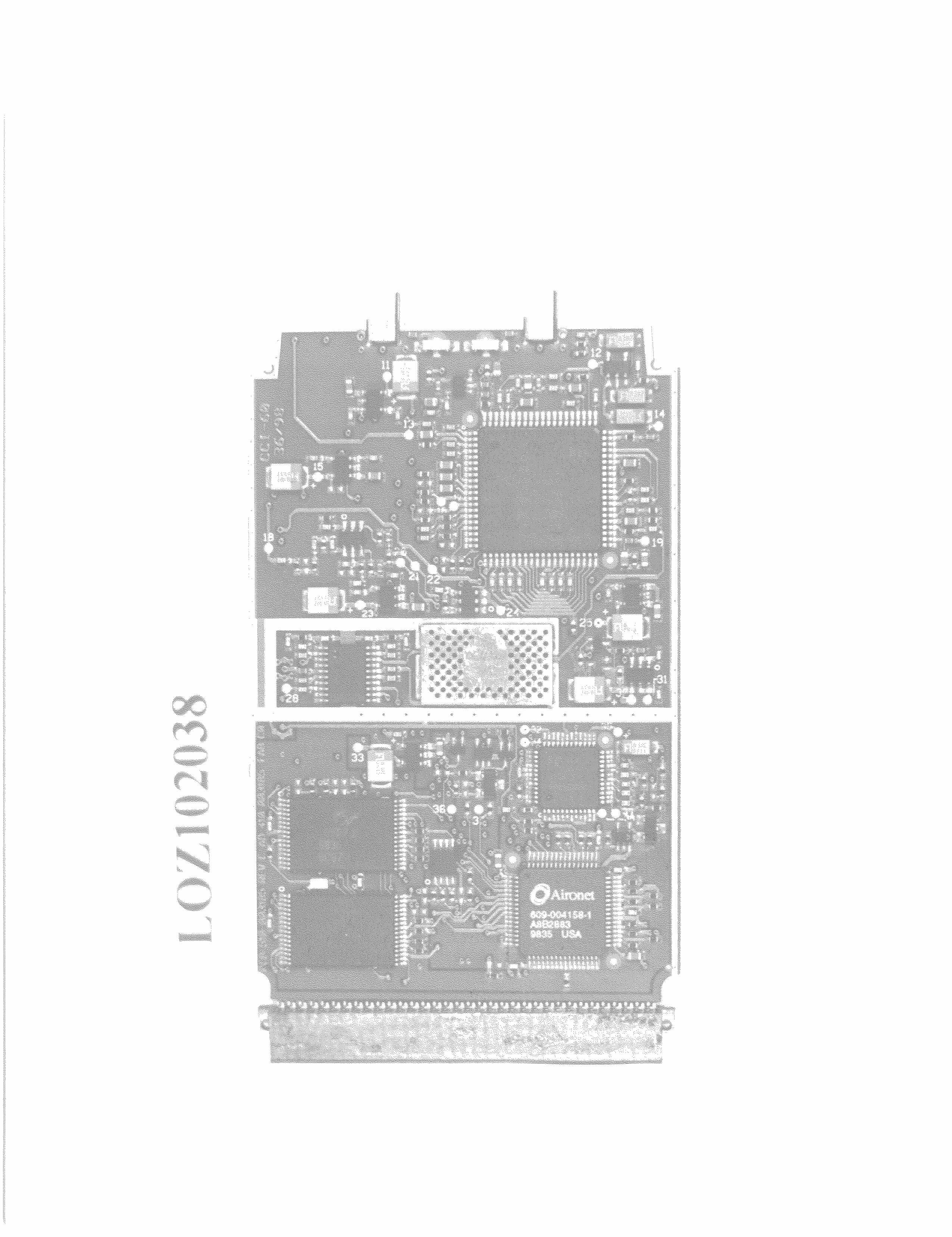
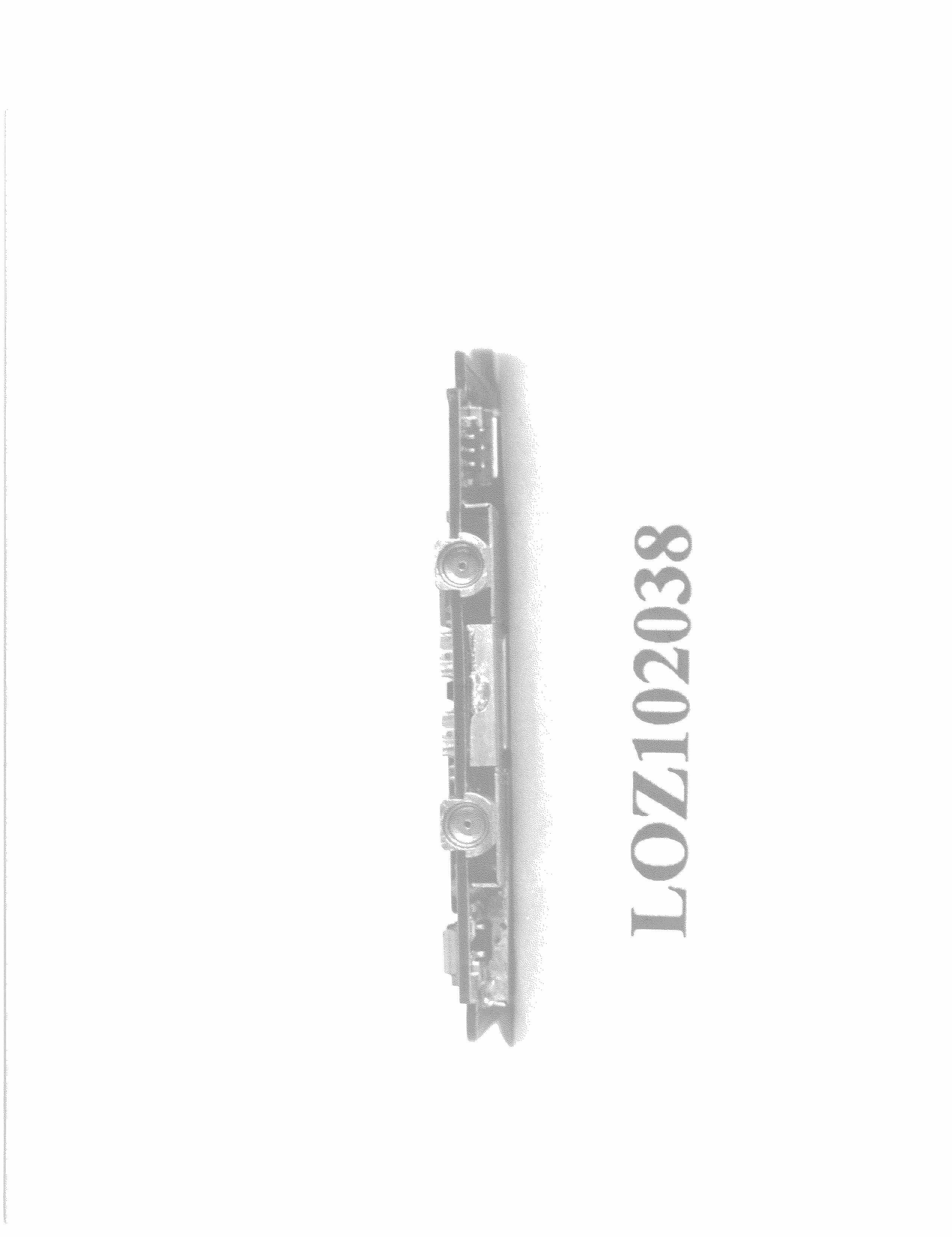
Document Text
Text extracted from the exhibit documents filed with the FCC. Open a document above to read the original.
Users Manual
Manufacturers Federal Communication Commission Declaration of Conformity Statement Models: PC4850 Manufacturer: Aironet Wireless Communications, Inc. 3875 Embassy Parkway Akron, OH 44333-8357 330-664-7900 This device complies with Part 15 rules. Operation is subject to the following two conditions: 1) this device may not cause harmful interference, and 2) this device must accept any interference received, including interference that may cause undesired operation. This equipment has been tested and found to comply with the limits of a Class B digital device, pursuant to Part 15 of the FCC Rules. These limits are designed to provide reasonable protection against harmful interference when the equipment is operated in a residential environment. This equipment generates, uses, and radiates radio frequency energy, and if not installed and used in accordance with the instructions, may cause harmful interference. However, there is no guarantee that interference will not occur. If this equipment does cause interference to radio or television reception, which can be determined by turning the equipment off and on, the user is encouraged to correct the interference by one of the following measures: Reorient or relocate the receiving antenna. Increase separation between the equipment and receiver. Connect the equipment into an outlet on a circuit different from which the receiver is connected. Consult the dealer or an experienced radio\TV technician. Department of Communications—Canada Canadian Compliance Statement This Digital apparatus meets all the requirements of the Canadian Interference - Causing Equipment Regulations. Cet appareil numerique respecte les exigences du Reglement sur le material broilleur du Canada. This device complies with RSS-210 of Industry of Canada. Operation is subject to the following two conditions: 1) this device may cause harmful interference, and 2) this device must accept any interference received, including interference that may cause undesired operation. The device is certified to the requirements of RSS-139-1 for 2.4 GHz spread spectrum devices. The use of this device in a system operating either partially or completely outdoors may require the user to obtain a license for the system according to the Canadian regulations. For further information, contact your local Industry Canada office. User Warning The Part 15 radio device operates on a non-interference basis with other devices operating at this frequency. Any changes or modification to said product not expressly approved by Aironet could void the user’s authority to operate this device.
Users Manual
Aironet Wireless Communications, Inc. • 3875 Embassy Parkway Akron, Ohio 44333-8357 www.aironet.com Technical User’s Guide 4800 Series Aironet Wireless LAN Adapter PC4800 DOC-710-00520-A0 Aironet Wireless Communications, Inc. No part of this document may be reproduced or transmitted in any means, elec- tronic or mechanical, for any purpose, without the written permission of Aironet. Information in this document is subject to change without notice. Aironet makes no representation or warranties with respect to the contents of this manual and specifically disclaims any express or implied warranties of merchantability or fitness for any particular purpose. © 1999 Aironet Wireless Communications, Inc. All rights reserved. LM4500 TM , AP4500 TM , PC4500 TM , LM4800 TM , AP4800 TM , PC4800 TM , and Aironet TM are trademarks of Aironet Wireless Communications, Inc. Other trademarks used are properties of their respective owners. Printed in USA DOC-710-00520-A0 Table of Contents i About the Technical User’s Guide ............................... vii Typographical Conventions ................................. viii Section 1 Installing the Wireless LAN Adapter ..............................9 Before You Start ...................................................10 Installing the Wireless LAN Adapter .....................11 Section 2 Drivers for Special Installations ...................................25 Driver Overview ....................................................25 Windows for Workgroups NDIS2 Installation ............................................................28 DOS NDIS2 Installation ........................................29 DOS Packet Driver Installation .............................31 ODI Driver Installation ..........................................33 General Information .............................................34 Driver Keywords and Settings ..............................36 Section 3 Using the WinDGS Utilities ..........................................49 WinDGS Commands Menu .........................................49 Select Card ..........................................................49 Load New Firmware .............................................49 Edit Properties ......................................................51 Statistics ...............................................................51 Status ...................................................................51 Link Test ...............................................................52 Site Survey ...........................................................54 Radio Off/On ........................................................56 Exit .......................................................................56 Options Menu ..............................................................56 Preferences ..........................................................56 Core Dump ...........................................................57 NDIS Driver Core Dump .......................................57 Using Edit Properties ...................................................57 System Parameters ..............................................58 Network Parameters ............................................60 RF Network Parameters .......................................60 Advanced (Infrastructure) .....................................62 Advanced (Ad Hoc/IBSS) .....................................64 Using the Site Survey Active Mode Feature ................65 Destination MAC Address ....................................65 Continuous Link Test ...........................................66 Destination is Another Aironet Device ..................66 Number of Packets ...............................................66 Packet Size ..........................................................66 Table of Contents ii Data Retries .........................................................66 Data Rates ...........................................................66 Delay Between Packets .......................................67 Packet Tx Type ....................................................67 Packet Success Threshold ...................................67 Using the Linkscope Utility ..........................................68 Section 4 Error Messages and Troubleshooting .........................69 Indicator LEDs ......................................................69 If Your Radio Fails to Establish Contact ...............71 Appendix A Aironet Wireless LAN Adapter Overview .....................73 Safety Information ................................................74 Radio Characteristics ...........................................76 Direct Sequence Radio Technology .....................76 Data Transparency and Protocols ........................76 Protocols Supported .............................................77 Radio Ranges ......................................................77 Radio Antenna .....................................................78 Security Features .................................................79 Terminology .........................................................79 System Configurations .........................................81 Coverage Options ................................................85 Appendix B PC Card Specifications ...............................................89 LAN Drivers Supported ........................................89 Radio Specifications .............................................90 Power Requirements ............................................91 Physical Specifications .........................................91 Mechanical Description ........................................92 Appendix C Channels .....................................................................93 Appendix D Declarations of Conformity ..........................................95 Appendix E Technical Support .....................................................101 About the Technical User’s Guide iii About the Technical Us…
Text truncated - open the document above for the full version.
Operational Description
Aironet Confidential107/15/99 Radio Circuit Description The JUPITER Spread Spectrum Transceiver operates in the 2.4 Ghz ISM band, using Direct Sequence modulation techniques. The transmit/receive and data packetization operations are under the control of a protocol processor (MAC) internal to the transceiver assembly. Logic Section : A digital ASIC is employed in the logic section of the radio, providing the following functions: 1) Generation of the spreading code, combination of the code with the incoming data stream. 2) Despreading and demodulation of the incoming baseband spread signal. 3) Determination of the transmit/receive sequence. RF Section (refer to JUPITER radio block diagram) : The transmitter chain includes a shaping bandpass filter followed by a vector modulator. This signal is further filter by a saw filter at the IF frequency of 280 Mhz. This signal is then mixed up to the 2400-2483.5 Mhz band. A RF filter at the output of the mixer removes any other mixing products. A power amplifier chain brings the signal up to the final output level of 250 mwatts. Through the TX/RX switch, the signal is passed through a dielectric bandpass filter to the antenna port. The radio has diversity, so two antenna ports are provided. Transmitter frequency is determined by the 44.0 Mhz reference oscillator, with +/- 12 ppm accuracy. The receiver utilizes the same antenna filtering and TX/RX, followed by a LNA. A mixer circuit brings the signal to the 280 Mhz IF, where a SAW filter shapes the IF spectral envelope. This filter provides the primary rejection against adjacent channel interference. An IF amplifier followed by an IF limiter brings the signal up to the level needed for the I and Q vector demodulator. A buffer amplifier and filter are used to shape the signal for the PHY digital ASIC which despreads and decodes the signal. The 280 Mhz voltage controlled oscillator is controlled by a synthesizer/PLL system comprised of a prescaler and programmable dividers. The 2132-2185 Mhz voltage controlled oscillator is also controlled by a synthesizer/PLL system. Both local oscillators use a reference signal for the PLL which is derived from the 44.0 Mhz master reference oscillator.
Parts List/Tune Up Info
Double Sided T Antenna: X-Y Plane Vertically Polarized Receive Horn Normalized to -29.5 dB -35-30-25-20-15-10 -5 0 w/o Radome w/Plastic Radome
Parts List/Tune Up Info
Double Sided T Antenna: X-Y Plane Vertically Polarized Receive Horn Normalized to -29.5 dB -35-30-25-20-15-10 -5 0 w/o Radome w/Plastic Radome
RF Exposure Info
Engineering Analysis of Transceiver Model PC4850 FCC ID: LOZ102038 To Federal Communications Commission Part 1.1310 Radio Frequency Exposure Limits & OET 65 Supplement C 07/19/99 This analysis was done per the requirements of Part 15.247.4 of the FCC rules as part of the FCC certification requirements for spread spectrum devices. The Aironet radio modules analyzed have a maximum TX power of 100mW (+20dBm) and all calculations were based on that power output (except where power reduction was required to meet the total EIRP limit of +36dBm). The formulas and Maximum Permissible Exposure (MPE) limit requirements referenced in this report can be found in FCC Bulletin OET-65 and specifically OET-65 Supplement C which addresses devices such as low power spread spectrum. All calculations were done in the worse case mode, the Uncontrolled environment with the radio duty cycle at 100%. It should be understood that under normal operating conditions, the Aironet radios would not operate at this duty cycle and most likely operate below 50% duty cycle. Based on the MPE calculation using the limits of the uncontrolled environment, the Aironet radio modules do not exceed the MPE requirements set forth in these documents providing the minimum safe distance between antenna and operator is met. For handheld or body worn systems, the recommend distance is about 2.8 cm (1.1 inch) from antenna and that is based on a 100% duty cycle. _______________________________________________ David A. Case NCE Senior Compliance and Reliability Engineer Aironet Wireless Communications 3875 Embassy Parkway Akron, OH 44333 330-664-7396 Page 1 I Equipment Under Test FCC ID:LOZ102038 Model:LM4850 Type:PCMCIA Wireless LAN Adapter Max Power0.1 Watts Duty CycleN \ A Max EIRP for antenna combinations 0dBi+20dBm II MPE Distances Calculations based on 100% duty cycle. AntennaTX PowerEIRPMPE Distance 0.0 dBi Antenna+20dBm+20dBm \ 0.1W 2.8 cm Page 2 III Maximum Permissible Exposure Ref: FCC Rules, CFR 47 1.1310 FCC Limits for Maximum Permissible Exposure (MPE) (A) Limits for Occupational/Controlled Exposure ________________________________________________________________________ Frequency E Field M Field Power Density Averaging Time Range Strength Strength (MHz) (V/m) (A/m) (mW/cm 2 ) (minutes) ________________________________________________________________________ 0.3-3.0 614 1.63 (100)*6 3.0-30 1842/f 4.89/f (900/f 2 )* 6 30-300 61.4 0.163 1.0 6 300-1500 -- -- f/300 6 1500-100,000 -- -- 5 6 ________________________________________________________________________ (B) Limits for General Population/Uncontrolled Exposure ________________________________________________________________________ Frequency E Field M Field Power Density Averaging Time Range Strength Strength | (MHz) (V/m) (A/m) (mW/cm 2 ) (minutes) ________________________________________________________________________ 0.3-1.34 614 1.63 (100)* 30 1.34-30 824/f 2.19/f (180/f 2 )* 30 30-300 27.5 0.073 0.2 30 300-1500 -- -- f/1500 30 1500-100,000 -- -- 1.0 30 ________________________________________________________________________ f = frequency in MHz *Plane-wave equivalent power density The uncontrolled environment represents the most restrictive limits. Page 3 IV. Summary In an uncontrolled environment, the maximum permissible exposure from a radio device operating at 2.4 Ghz is 1mW/cm2 average over a 30 minute period. In the controlled environment, the maximum permissible exposure from a radio device operating at 2.4 Ghz is 5mW/ cm2 over a 6 minute period. Since the analysis is favorable in the Uncontrolled Environment, it is unnecessary to analyze the device to the less restrictive limits of the Controlled Environment or Partial Body Exposure Based on the calculated distance (determined by the uncontrolled environment) the minimum recommended mounting distance is 2.8cm away from the body (1.37 inches) based on the radio operating at a 100% duty cycle. Excerpts from OET 65-C Transmitters using a monopole or dipole type antennas that are < 0.2W@2450 Mhz These transmitters are not expected to exceed 1.0mW/cm2 at 2450 Mhz Transmitters that are carried next to body if user or operate at a distance of less then 5cm from user whose power is >0.2W@2450 Mhz : Generally above 200mW EIRP at 2450 MHz, the potential for exceeding MPE \ SAR limits is dependent on design of antenna and device operating condition, Page 4 Formulas 1) For calculating MPE Distance 2) Conversion mW to dBm 3) Conversion dBm to mW 4) Power Density Page 5 References 1) CFR 47, Federal Communication Commission FCC Parts 1.1310 and FCC Part 15.247 (1998) EIRP 4 π 10 = EIRP log10() . mW = logdBm log 1 dBm 10 . = logmW EIRP 4 π r 2 = EIRP r Pd 2) FCC Office of Engineering and Technology Bulletin 65 Edition 97-01 Evaluating Compliance with the FCC Guidelines for Human Exposure to Radio Frequency Electromagnetic Fields. 3) FCC Office of Engineering and Technology Bulletin Supplement C Evaluating Compliance with the FCC Guidelines for Human Exposure to Radio Frequency Electromagnetic Fields. 4) IEEE (ANSI) C95.1-1991 IEEE Standard for Safety Levels with Respect to Human Exposure to Radio Frequency Electromagnetic Fields, 3Khz to 300 Ghz. 5) Reference Data For Engineers, 8 th Edition, Sams Publishing 6) Part 15 Devices and RF Safety , 1998 CE Reference Guide 7) Radio Frequency Radiation from Portable and Mobile Devices, 1998 CE Reference Guide.
RF Exposure Info
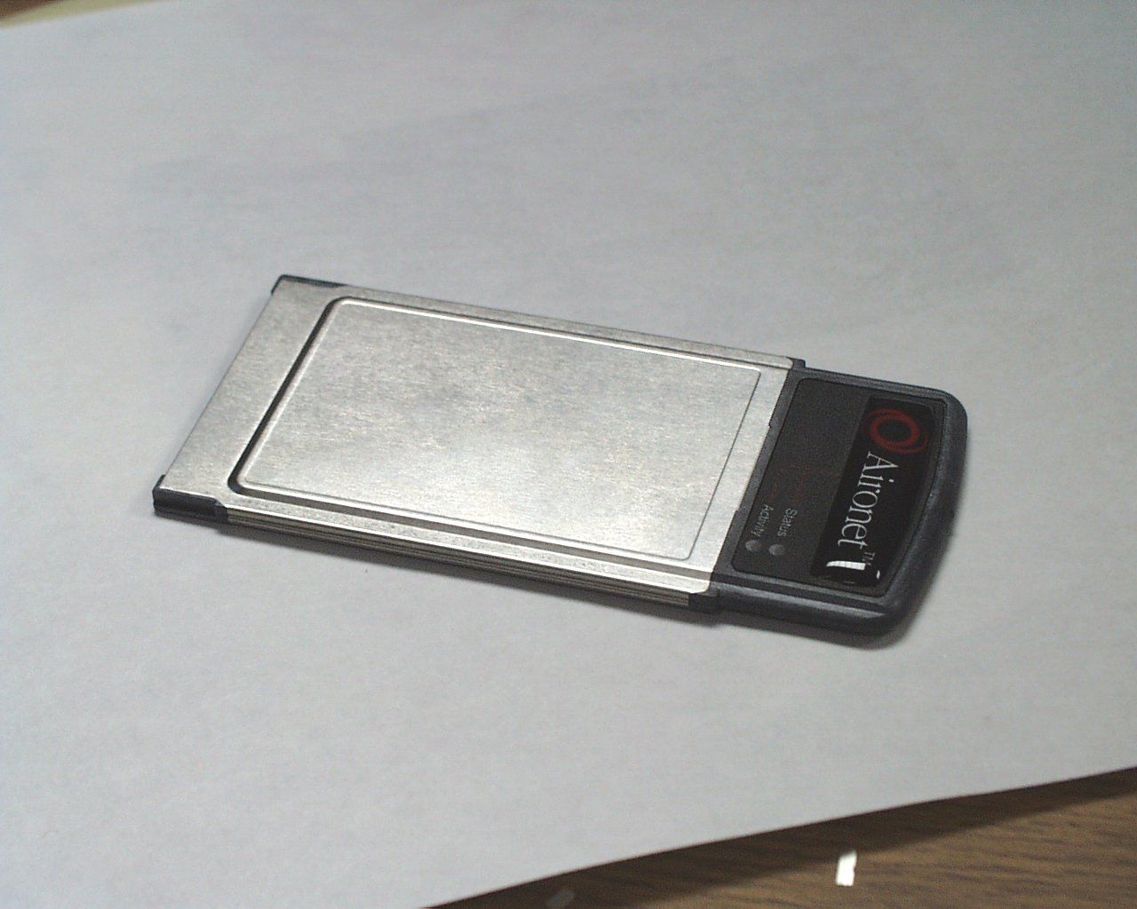
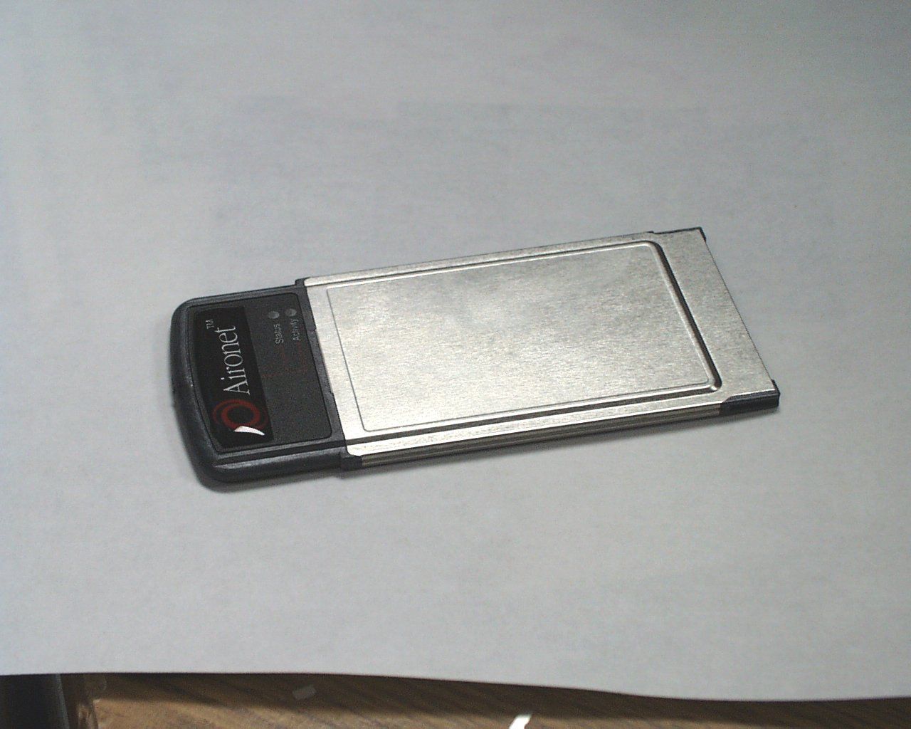
11/08/99 FCC ID: LOZ102038 Ref # EA94923 In response to your request for additional information. 1) The PCMICA card can operate at either 3.3 volt or 5 volt DC input. 2) This radio only supports the molded one piece antenna. Please disregard references in preliminary manual on other antennas. No external antenna can be used with this card. The final product will not include any antenna connectors accessible to the end user. (Please see attached picture) 3) The card will be factory programmed for the lowest power setting to comply with SAR requirements as set forth in the FCC rules under 15.247 and OET 65 C. This cannot be changed by the end user. 4) The higher power system (74mW) will be restricted for use in mobile devices only. This information will be provided to our resellers , VARs, and OEM customers as well as part of our training literature. (Currently Aironet does not sell directly to the general public). Again the radio power can only be set by the factory
Test Report
FCC ID: LOZ102038 MFA p9970002, d9970040 Date:July 20, 1999 Federal Communications Commission EQUIPMENT APPROVAL SERVICES P.O. Box 358315 Pittsburgh, PA 15251-5315 Attention:Authorization & Evaluation Division Applicant:Aironet Wireless Communications, Inc. Equipment:PC4850 FCC ID:LOZ102038 FCC Rules:15.247, Confidentiality Gentlemen: On behalf of the Applicant, enclosed please find Application Form 731, Engineering Test Report and all pertinent documentation, the whole for approval of the referenced equipment as shown. Filing fees are attached. We trust the same is in order. Should you need any further information, kindly contact the writer who is authorized to act as agent. Sincerely yours, William H. Graff enclosure(s) CERTIFIED MAIL, R.R.R. cc: Applicant WHG/cvr FCC ID: LOZ102038 MFA p9970002, d9970040 Date:July 20, 1999 Federal Communications Commission EQUIPMENT APPROVAL SERVICES P.O. Box 358315 Pittsburgh, PA 15251-5315 Attention:Authorization & Evaluation Division Applicant:Aironet Wireless Communications, Inc. FCC ID:LOZ102038 Equipment:PC4850 Subject:Electronically Filed FORM 731 Confirmation: Gentlemen: As per instructions received, enclosed herewith please find completed Remittance Advice Form 159 for the referenced equipment, bearing original signature, and the application having been electronically filed. Sincerely yours, William H. Graff enclosure(s) CERTIFIED MAIL, R.R.R. cc: Visa cc: File WHG/cvr FCC ID: LOZ102038 MFA p9970002, d9970040 LIST OF EXHIBITS (FCC CERTIFICATION (TRANSMITTERS) - REVISED 9/28/98) APPLICANT:Aironet Wireless Communications, Inc. FCC ID:LOZ102038 BY APPLICANT: 1. LETTER OF AUTHORIZATION 2. IDENTIFICATION DRAWINGS ID LABEL LOCATION INFO ATTESTATION STATEMENT(S) LOCATION OF COMPLIANCE STATEMENT 3. DOCUMENTATION: 2.1033(b) (3)USER MANUAL(S) (4)OPERATIONAL DESCRIPTION (5)BLOCK DIAGRAM (5) SCHEMATIC DIAGRAM (7) EXTERNAL PHOTOGRAPHS INTERNAL PHOTOGRAPHS 4. DRAFT SPECIFICATION INFORMATION 5. PARTS LIST/TUNE UP INFO BY M.F.A. INC. A.TESTIMONIAL & STATEMENT OF CERTIFICATION B.STATEMENT OF QUALIFICATIONS FCC ID: LOZ102038 MFA p9970002, d9970040 Sub-part 2.1033(c): EQUIPMENT IDENTIFICATION FCC ID: LOZ102038 NAMEPLATE DRAWING ATTACHED, EXHIBIT 1. LOCATION AS PER LABEL DRAWING(S) DATE OF REPORT July 20, 1999 SUPERVISED BY:William H. Graff FCC ID: LOZ102038 MFA p9970002, d9970040 THE APPLICANT HAS BEEN CAUTIONED AS TO THE FOLLOWING: 15.21INFORMATION TO USER. The users manual or instruction manual for an intentional radiator shall caution the user that changes or modifications not expressly approved by the party responsible for compliance could void the user's authority to operate the equipment. 15.27(a)SPECIAL ACCESSORIES. Equipment marketed to a consumer must be capable of complying with the necessary regulations in the configuration in which the equipment is marketed. Where special accessories, such as shielded cables and/or special connectors are required to enable an unintentional or intentional radiator to comply with the emission limits in this part, the equipment must be marketed with, i.e. shipped and sold with, those special accessories. However, in lieu of shipping or packaging the special accessories with the unintentional or intentional radiator, the responsible party may employ other methods of ensuring that the special accessories are provided to the consumer, without additional charge. Information detailing any alternative method used to supply the special accessories for a grant of equipment authorization or retained in the verification records, as appropriate. The party responsible for the equipment, as detailed in § 2.909 of this chapter, shall ensure that these special accessories are provided with the equipment. The instruction manual for such devices shall include appropriate instructions on the first page of text concerned with the installation of the device that these special accessories must be used with the device. It is the responsibility of the user to use the needed special accessories supplied with the equipment. FCC ID: LOZ102038 MFA p9970002, d9970040 TABLE OF CONTENTS RULEDESCRIPTIONPAGE .Test Report1 2.1033(c)General Information Required2 .Standard Test Conditions and Engineering Practices6 15.247(b)Maximum Peak Output Power7 15.247(c)Out of Band Emissions10 15.205Restricted Bands of Operation12 15.247(a)(2)Allowed Occupied Bandwidth30 15.247(d)Transmitter Power Density37 15.247(e)Processing Gain (Summary37 15.207A/C Powerline Conducted Emissions39 1.1310Radio Frequency Radiation Exposure Evaluation45 FCC ID: LOZ102038 MFA p9970002, d9970040 PAGE NO.1 of 45. Required information per ISO/IEC Guide 25-1990, paragraph 13.2: a)TEST REPORT b) Laboratory: (FCC: 31040/SIT) (Canada: IC 2044) M. Flom Associates, Inc. 3356 N. San Marcos Place, Suite 107 Chandler, AZ 85225 c) Report Number:d9970040 d) Client:Aironet Wireless Communications, Inc. P.O. Box 5292 Fairlawn, OH 44334-0292 e) Identification:PC4850 FCC ID: LOZ102038 Description:Direct Sequence Spread Spectrum f) EUT Condition:Not required unless specified in individual tests. g) Report Date:July 20, 1999 EUT Received:July 7, 1999 h, j, k):As indicated in individual tests. i) Sampling method:No sampling procedure used. l) Uncertainty:In accordance with MFA internal quality manual. m) Supervised by: William H. Graff n) Results:The results presented in this report relate only to the item tested. o) Reproduction:This report must not be reproduced, except in full, without written permission from this laboratory. FCC ID: LOZ102038 MFA p9970002, d9970040 PAGE NO.2 of 45. LIST OF GENERAL INFORMATION REQUIRED FOR CERTIFICATION IN ACCORDANCE WITH FCC RULES AND REGULATIONS, VOLUME II, PART 2 AND TO 15.247, Confidentiality Sub-part 2.1033 (c)(1):NAME AND ADDRESS OF APPLICANT: Aironet Wireless Communications, Inc. 3875 Embassy Parkway Akron, OH 44333 MANUFACTURER: Applicant (c)(2):FCC ID:LOZ102038 MODEL NO:PC4850 (c)(3):INSTRUCTION MANUAL(S): PLEASE SEE ATTACHED EXHIBITS (c)(4):TYPE OF EMISSION…
Text truncated - open the document above for the full version.
Test Report
Aironet Confidential207/15/99 PRODUCT NAME:AIRONET JUPITER RADIO NAME OF TEST:The Processing Gain of a Direct Sequence System. FCC Part 15.247 (e) specifies: The processing gain of a direct sequence system shall be at least 10 dB. Guidance on measurement by FCC The processing gain may be measured using the CW jamming margin method. The test consists of stepping a signal generator in 50khz increments across the passband of the system. At each point, the generator level required to the produce the recommended Bit Error Rate (10-5) is recorded. This is the jammer level. The output power of the transmitting unit is measured at the same point. The Jammer to Signal (J/S) ratio is then calculated. Discard the worst 20% of the J/S data points. Total losses in a system including transmitter and receiver, should be assumed to be no more than 2 dB. therefore, processing gain = S/N + Mj + Lsys Where : S/N = Signal to noise ratio required at the receiver output for 10-5 error rate of a ideal receiver for your demodulation scheme Mj = Jammer to signal ratio Lsys = System losses (2dB max) Test results : for 1 mb data rate: S/N = 13 dB ; taken from Wireless Information Networks by Pahlavan & Levesque Mj = - 2.5 dB ; worst case jamming margin from tests in lab Lsys = 0.5 dB ; system losses therefore the processing gain at 1mb is 13 dB - 2.5 dB + 0.5 dB = 11.0 dB for 2 mb data rate: S/N = 13 dB ; taken from Wireless Information Networks by Pahlavan & Levesque Mj = - 2.9 dB ; worst case jamming margin from tests in lab Lsys = 1.0 dB ; system losses therefore the processing gain at 2mb is 13 dB - 2.9 dB + 1.0 dB = 11.1 dB Aironet Confidential307/15/99 for 5.5 mb data rate: S/N = 13.6 dB ; taken from Harris CCK encoding modulation Mj = - 5.2 dB ; worst case jamming margin from tests in lab Lsys = 2.0 dB ; system losses therefore the processing gain at 5.5mb is 13.6 dB - 5.2 dB + 2.0 dB = 10.4 dB for 11 mb data rate: S/N = 16.0 dB ; taken from Harris CCK encoding modulation Mj = - 7.3 dB ; worst case jamming margin from tests in lab (after 20% discarded) Lsys = 2.0 dB ; system losses therefore the processing gain at 11mb is 16.0 dB - 7.3 dB + 2.0 dB = 10.7 dB Aironet Confidential407/15/99 AIRONET CONFIDENTIAL RF Systems Engineering dwg: J. Friedmann File:FCC025_2.ds4 Date: 3/21/96 rev: 2.4 Ghz SPREAD SPECTRUM RADIO, 2nd GEN Jammer Test, R240 eng: J. Friedmann Transmitter Jamming Test Setup AIRONET Sig GenPower Meter Receiver Bit Error Rate Tester splitsum
Test Report
FCC ID: LOZ102038 MFA p9970002, d9980017 PAGE NO.38 of 45. AMENDED August 11, 1999 NAME OF TEST:Emission Masks (Occupied Bandwidth) Indicating 6/20 dB Bandwidth g9980017: 1999-Aug-11 Wed 09:03:00 STATE: 2:High Power CORR'D RES BW 3 kHzVBW 10 kHzSWP 1.50 ksec ATTEN 10 dBREF 0.0 dBm 10 dB/ POS PK CENTER 2.439 55 GHzSPAN 5.00 MHz MKR 2.440 230 GHz -33.40 dBm POWER:HIGH MODULATION:11 MB/S CCK SPECTRAL POWER DENSITY SUPERVISED BY:William H. Graff, Director of Engineering
Test Report
FCC ID: LOZ102038 MFA p9980017, d9990066 Date:September 27, 1999 Federal Communications Commission EQUIPMENT APPROVAL SERVICES P.O. Box 358315 Pittsburgh, PA 15251-5315 Attention:Authorization & Evaluation Division Applicant:Aironet Wireless Communications, Inc. Equipment:LM4800B (Without Antenna) PC4800B (With Antenna) FCC ID:LOZ102038 FCC Rules:15.247 Subject:Class II Permissive Change Gentlemen: On behalf of the Applicant, enclosed please find Application Form 731, Engineering Test Report, the whole in support of the referenced subject. All documentation has been submitted with the original application which is still pending under the above FCC ID, EA949234 (7/23/99). Filing fees are attached. We trust the same is in order. Should you need any further information, kindly contact the writer who is authorized to act as agent. Sincerely yours, William H. Graff, Director of Engineering enclosure(s) Electronic Filing cc: Applicant WHG/cvr FCC ID: LOZ102038 MFA p9980017, d9990066 Sub-part 2.1033(c): EQUIPMENT IDENTIFICATION FCC ID: LOZ102038 NAMEPLATE DRAWING ATTACHED, EXHIBIT 1. LOCATION AS PER LABEL DRAWING(S) DATE OF REPORT September 27, 1999 SUPERVISED BY:William H. Graff, Director of Engineering FCC ID: LOZ102038 MFA p9980017, d9990066 THE APPLICANT HAS BEEN CAUTIONED AS TO THE FOLLOWING: 15.21INFORMATION TO USER. The users manual or instruction manual for an intentional radiator shall caution the user that changes or modifications not expressly approved by the party responsible for compliance could void the user's authority to operate the equipment. 15.27(a)SPECIAL ACCESSORIES. Equipment marketed to a consumer must be capable of complying with the necessary regulations in the configuration in which the equipment is marketed. Where special accessories, such as shielded cables and/or special connectors are required to enable an unintentional or intentional radiator to comply with the emission limits in this part, the equipment must be marketed with, i.e. shipped and sold with, those special accessories. However, in lieu of shipping or packaging the special accessories with the unintentional or intentional radiator, the responsible party may employ other methods of ensuring that the special accessories are provided to the consumer, without additional charge. Information detailing any alternative method used to supply the special accessories for a grant of equipment authorization or retained in the verification records, as appropriate. The party responsible for the equipment, as detailed in § 2.909 of this chapter, shall ensure that these special accessories are provided with the equipment. The instruction manual for such devices shall include appropriate instructions on the first page of text concerned with the installation of the device that these special accessories must be used with the device. It is the responsibility of the user to use the needed special accessories supplied with the equipment. FCC ID: LOZ102038 MFA p9980017, d9990066 TABLE OF CONTENTS RULEDESCRIPTIONPAGE .Test Report1 .Expository Statement for Permissive Changes2 2.1033(c)General Information Required3 .Standard Test Conditions and Engineering Practices7 15.247(b).Maximum Peak Output Power8 15.247(c). Out of Band Emissions10 FCC ID: LOZ102038 MFA p9980017, d9990066 PAGE NO.1 of 16. Required information per ISO/IEC Guide 25-1990, paragraph 13.2: a)TEST REPORT b) Laboratory: (FCC: 31040/SIT) (Canada: IC 2044) M. Flom Associates, Inc. 3356 N. San Marcos Place, Suite 107 Chandler, AZ 85225 c) Report Number:d9990066 d) Cli…
Text truncated - open the document above for the full version.
Contact Information
Applicant
Donald I. Sloan(Sr Engineering V.P.)
330 664-7900Fax: 330-664-7301
Technical Contact
Morton FlomMorton Flom
[email protected]480 967 6788
3356 N. San Marcos Place · Chandler, Arizona · United States
Non-Technical Contact
M. Flom Associates, Inc.Morton Flom
[email protected]480 926 3100
Test Firm
M. Flom Associates, Inc.Morton Flom
Technical Specifications
| # | Rule Parts | Frequency Range | Power Output |
|---|---|---|---|
| 1 | 15C | 2.41 GHz - 2.46 GHz | 74.00 mW |
Other Applications from Aironet Wireless Communications Inc
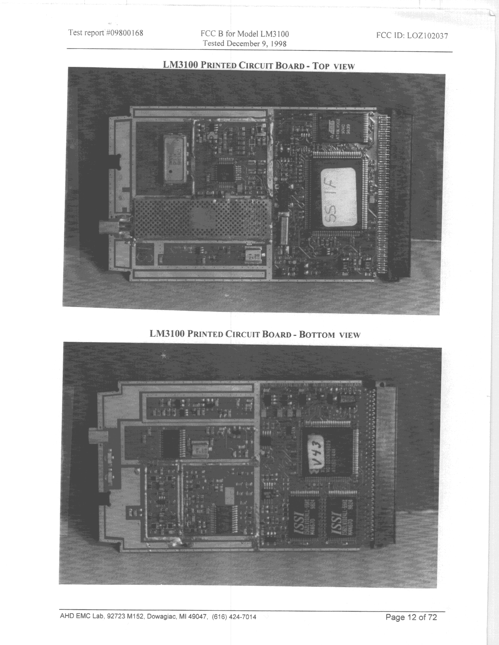
LOZ102037
Mar 31, 1999PCMCIA Card Transmitter.
Equipment Class
DSS - Part 15 Spread Spectrum Transmitter
LOZ102036
Feb 11, 1999DSS - Part 15 Spread Spectrum Transmitter
Equipment Class
DSS - Part 15 Spread Spectrum TransmitterLOZ102034
Mar 25, 1998PCMCIA WLAN Maximum output power: 250 mW
Equipment Class
DSS - Part 15 Spread Spectrum Transmitter