LP59003TIR Remote Extender
Kidder Industrial Ltd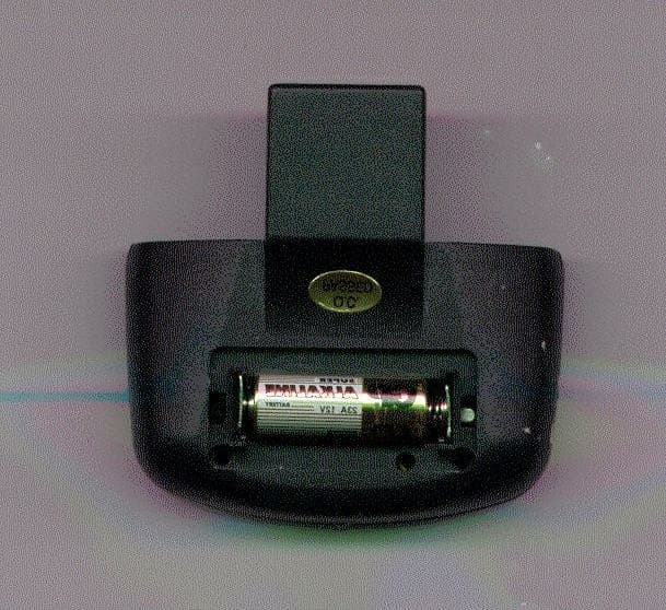
Click to zoom
Application Details
- Equipment Class
- DSC - Part 15 Security/Remote Control Transmitter
- Date of Grant
- Jun 03, 2002
- Application Purpose
- Original Equipment
- Date of Application
- Jun 03, 2002
- Equipment Note
- IR Remote Extender
- Frequency Range
- 443.50000000 - 444.50000000
- Company
- Kidder Industrial Ltd
- Country
- Hong Kong
Documents & Files
Document Text
Text extracted from the exhibit documents filed with the FCC. Open a document above to read the original.
Users Manual
REMOTE CONTROL EXTENDING SYSTEM USER MANUAL With the Remote Control Extending System, you have complete control of your digital satellite receiver from anywhere inside of the house. It converts IR (Infra-Red) signals emitted by the remote control into a powerful radio signal which is then broadcast up to a distance of 150 feet to the receiver base station. No tools are needed to install the Remote Control Extending System. The Remote Control Extending System consists of two components; the transmitter (which attaches to the front of the remote control), and the receiver “base station” (which is placed in the room where the digital satellite receiver is located). Receiver Base Station Installation Place the receiver base station in the room where your digital satellite receiver is located. Choose a location that is near an electrical outlet on an opposing wall to where your equipment is installed. Point the front of the base station towards the receiver. Try to use your remote control from your chosen location to confirm that it is within the operating “view” of your digital satellite receiver. Plug the AC power adapter (included with your Remote Control Extending System) in the wall outlet. Attach the small plug from the transformer into the jack on the receiver base station. The power light should illuminate. Extend the antenna fully. The base station is ready for use. Using the Control Cable With the proper connection, you can hide the receiver base station behind your entertainment system and still control your digital satellite receiver. First, plug the control cable into the side of the receiver base station. The emitter end of the control cable must then be attached to the front of the satellite receiver to communicate with the remote control sensor. The remote control sensor is commonly identifiable by a small plastic window. You may have to try different locations for optimum performance. You can permanently attach the emitter using the peel-and-stick backing. This attachment should not interfere with normal operation. Transmitter Installation Using a small screwdriver or nail-file, open the battery cover of the transmitter and install the supplied battery being careful to match the +/- signs on the battery with the same marks inside the battery compartment. Replace the top cover. Remove the battery cover from the remote control. Slide and snap the transmitter with the attached battery cover into place on the remote replacing the old cover. It is recommended to change your batteries in your remote control to ensure proper operation of the Remote Control Extending System. Weak batteries in your remote control will reduce range and can cause erratic operation of the System. You are now ready to use your Remote Control Extending System equipped remote control. You should find that using your remote control from another room will work just as though you were right in front of your digital satellite receiver. Note that you do not need to point it toward the room for it to work. The signals are broadcast from the transmitter in all directions – even through walls, ceilings, and furniture! Battery Replacement Your operating range will start to decrease as the battery life decreases. Replacement batteries are conveniently available at most electronic stores. To replace the battery, follow the directions above. Remember to dispose of the old battery properly. Battery : Type mn21 12v or equivalent. NOTE: THE MANUFACTURER IS NOT RESPONSIBLE FOR ANY RADIO OR TV INTERFERENCE CAUSED BY UNAUTHORIZED MODIFICATIONS TO THIS EQUIPMENT. SUCH MODIFICATIONS COULD VOID THE USER'S AUTHORITY TO OPERATE THE EQUIPMENT. FCC ID:LP59003T
Cover Letter(s)
Form Letters1 TIMCO TIMCOTIMCO TIMCO ENGINEERING INC. 849 NW State Road 45 Newberry, Florida 32669 http://www.timcoengr.com 888.472.2424 F 352.472.2030 email: tei@t imcoengr.com May 29, 2002 FCC SUBJECT: KIDDER INDUSTRIAL LIMITED FCC ID: LP59003T To Whom It May Concern: 1. You will notice that in the original test report the limits for the restricted bands are not shown correctly, this has been corrected in the supplemental sheets that we have enclosed. 2. The bandwidth test to ensure band edge compliance in the Test Report was not shown correctly. This has been corrected in the supplemental sheet that we have enclosed. Sincerely, Frank
ID Label/Location Info
REMOTE TRANSMITTER FCC ID:LP59003T MADE IN CHINA This device complies with part 15 of the FCC rules. Operation is subject to the following two conditions: (1) this device may not cause harmful interference, and (2) this device must accept any interference received including interference that may cause undesired operation.
Operational Description
TECHNICAL DESCRIPTION OF OPERATION LP59003T The remote transmitter (described in the attached exhibits as LP59003T) is a device that detects infrared (IR) light pulses from a hand-held remote control and uses radio frequency (RF) to link it back to it’s original infrared-controlled component, such as a VCR or stereo receiver, via the corresponding remote receiver. A) The remote transmitter is not used for continuous transmission. 1) No voice communications are used. 2) There are no transmissions at predetermined intervals. B) No polling or supervision transmissions are made. C) The remote transmitter operates using a manual push buttons on the attached hand- held remote control that automatically deactivate the remote transmitter when released. D) The remote transmitter does not automatically activate: Only manual operation is possible. E) The remote transmitter is fixed tuned to transmit at 444 MHZ RF signal. The 444 MHZ is modulated by an IR remote control pulse train. As referred to in the attached exhibits, the remote transmitter is powered by a 12 volts DC battery. The circuit contains one (1) IR diode detector and two (2) transistors. D1 is responsible for detecting the generated IR pulse train for the desired function. Q1 is a switch fro activating Q2 which supplies power to Q2 while there is a key being pressed on the attached hand-held remote control. Q2 is an oscillator generating the 444 MHZ RF signal through a tuned tank circuit. When IR remote control key has been pressed, Q1 remains switched off therefore there will be no power through the oscillator circuit and no transmissions can occur. When a hand-held remote control key has been pressed, D1 detector will cause Q1 transistor to be switched On/OFF at the remote control pulse train rate, causing the oscillator to generate a burst of RF signal. The transmission will automatically cease when the hand-held remote control key is released.
Test Report
Product Safety Engineering, Inc 12955 Bellamy Brothers Blvd. Dade City, FL 33525 Tel (352) 588-2209 Fax (352) 588-2544 Kidder RE 200 Transmitter Measured @ 3 Meters FrequencySpec Limit Measurement) LimitPolarityHeight (GHz)(dBμV/M)(dBμV/M)(cm) 1.33054.053.4-0.6Vertical100 1.77361.160.9-0.2Vertical100 2.22154.051.6-2.4Vertical100 Page A4 of A4
Contact Information
Test Firm
Product Safety Engineering, Inc.Steven Hoke
Technical Specifications
| # | Rule Parts | Frequency Range | Power Output |
|---|---|---|---|
| 1 | 15.231 | 443.5 MHz - 444.5 MHz | - |