LPV-SRF2010Stereo RF Cordless Headphone Receiver
Alford Industries Ltd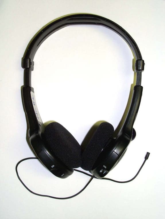
Click to zoom
Application Details
- Equipment Class
- CRR - Superregenerative Receiver
- Date of Grant
- Mar 24, 2004
- Application Purpose
- Original Equipment
- Date of Application
- Mar 24, 2004
- Equipment Note
- Stereo RF Cordless Headphone Receiver
- Frequency Range
- 49.83000000 - 49.89000000
- Company
- Alford Industries Ltd
- Country
- Hong Kong
Documents & Files
Document Text
Text extracted from the exhibit documents filed with the FCC. Open a document above to read the original.
Users Manual
INSTRUCTION MANUALINSTRUCTION MANUAL RADIO FREQUENCY CORDLESS HEADPHONE SYSTEM RADIO FREQUENCY CORDLESS HEADPHONE SYSTEM SYSTEM COMPONENTSSYSTEM COMPONENTS TRANSMITTER Audio cord with 3.5mm plug On/Off Indicator 12V 100mA AC/DC ADAPTER 3.5mm to RCA (STEREO) PATCH CORD 3.5mm to 6.3mm PLUG ADAPTER CORDLESS HEADPHONECORDLESS HEADPHONE Battery Compartment On/Off Switch Power On/Off Indicator Volume Control SPF-2010 Communication level mode Radio Frequency(49.86MHz) Communication level Stereo Power requirement: Transmitter 12V 100mA AC/DC adapter Headphone(receiver) 3V (2x1.5V AAA carbon, alkaline, Ni-Cd batteries) Frequency Response 30-10000Hz S/N Ratio 42 dB Distortion 1% Max operating distance Maximum 25 meters Weight: Transmitter (without adapter) 105g Headphone (without batteries) 122g Standard Accessories AC/DC power adapter(for transmitter) 3.5mm to 6.3mm Plug Adapter3.5mm to RCA (stereo) Patch cord SPECIFICATIONS TROUBLESHOOTING GUIDETROUBLESHOOTING GUIDE SYMPTOM CAUSE SOLUTION SYMPTOM CAUSE SOLUTION Poor sound qualityPoor sound quality No soundNo sound Headphone is not turned on. Batteries are exhausted. Transmitter’s power is off. Headphones’ volume is completelyturned down. Automatic”muting”at headphone. Headphones’ batteries are weak. Out of range Turn on the headphone. Change batteries. Turn on the transmitter’s power.Turn the volume up. Move closer to transmitter.Change batteries. Move closer to transmitter oradjust the transmitter antenna Wire antenna This device complies with Part 15 of the FCC Rules. Operation is subject to the followingtwo conditions:1.This device may not cause harmful interference,and2.This device must accept any interference received.Including interference that may cause undesired operation. 15-Mar-04 R.03 For the following illustration, we use television as the audio source equipment.For actual usage, you may select any type of audio source equipment for connection. INSTALLATION I.Equipment with 3.5mm phone jack If the audio-out jack of yourequipment is a type, connect the audio out jackwith the audio cord attach-ed at the back of the trans-mitter. 3.5mm II.Equipment with 6.3mm phone jack If the audio-out jack of yourequipment is a 6.3mmtype, plug in the supplied“ to the audio-out jack of your equipment,then connect it with theaudio cord attached at theback of the transmitter. 3.5mm to 6.3mm plug adapter” III.Equipment with RCA jack If the audio-out jack of yourequipment is a RCA type,plug in the supplied to the audio - out of your equipment , then con-nect it with the audio cordattached at the back of thetransmitter. “3.5 mm to RCA (stereo) patchcord ” 3.5mm to 6.3mm plug adapter 3.5mm to RCA (Stereo) patch cord DC-IN ON OFF DC-IN ON OFF DC-IN ON OFF IMPORTANT:CONNECTION TO MONO EQUIPMENT When your audio/video equipment is a type. Only one side of the headphone is heard. mono POSITION OF THE TRANSMITTER This cordless headphone system is designed for indoor use within a distance of 25 meters betweenthe transmitter and the receiver.Note: Do not place the transmitter in a location near sources such as radiators, heater, or any place subject to direct sunlight or vibration. 1.Turn on your audio equipment and the transmitter. You will be able to see the LED power indicator light go on. 2.Set the volume of your audio equipment at medium level.3.Turn on the headphone receiver, the LED, power indicator should go on. Adjust the size of the headphone by pulling up or down on each side until it fits on your head comfortably. Adjust theaudio volume as desired. -AAA+ +AAA- 3.5mm to RCA(Stereo) patch cord black red OPERATION BATTERY CHANGE 1.Make sure headphone receiver is off.2.Slide open battery compartment cover.3.Insert two AAA (1.5V) batteries with the (+) and (-) poles correctly aligned into the battery compartment. Alkalinetype or Ni-Cd rechargeable type batteries are recommend-ed. 4.Close the battery compartment. DC-IN ON OFF Do not attach 13-Mar-04 R.01
Block Diagram
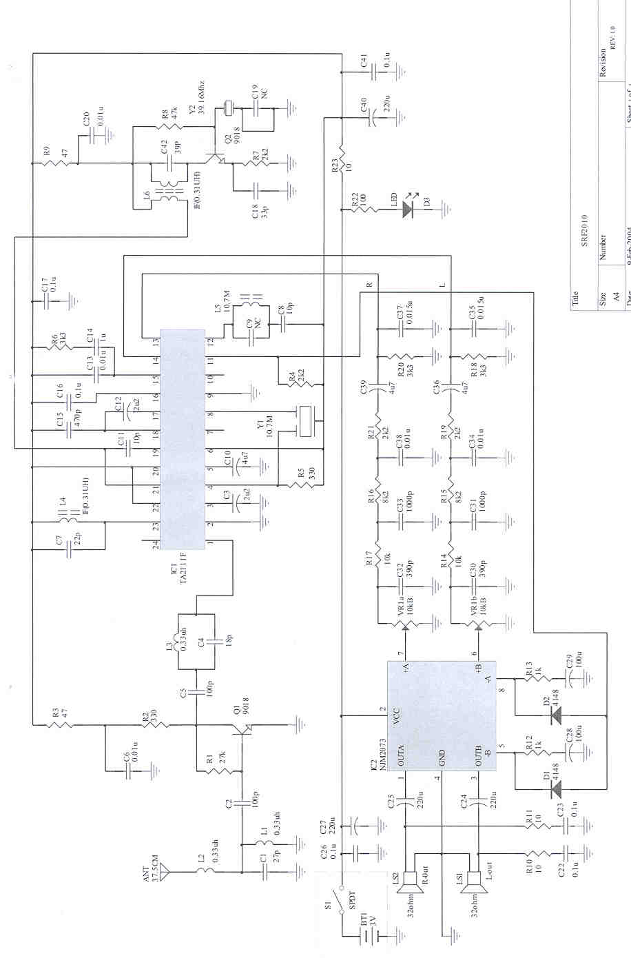
A L F O R D SRF2010 Receiver Block Diagram ANT RF LNA MIX IF AMPLIFIER FM DET STEREO DECODE STEREO AUDIO POWER AM PLIFIER OSCILLA TION SWITCH BA TTER Y SPEAKER STEREO MUTE
External Photos
FCC ID: LPV-SRF2010 ——————————————————————————————————————————————— Advanced Compliance Lab, 6 Randolph Way, Hillsborough, NJ 08844, Tel: (908) 927-9288 Fax: (908) 927-0728 16 Figure 6.1 External view
ID Label/Location Info
FCC ID: LPV-SRF2010 ——————————————————————————————————————————————— Advanced Compliance Lab, 6 Randolph Way, Hillsborough, NJ 08844, Tel: (908) 927-9288 Fax: (908) 927-0728 8 2. PRODUCT LABELING This device complies with part 15 of the FCC Rules. Operating is subject to the following two conditions: (1) This device may not cause harmful interference, and (2) this device must accept any interference received, including interference that may cause undesired operation. Figure 2.1 FCC ID Label Figure 2.2 Location of the Label FCC LABEL FCC ID: LPV-SRF2010
Internal Photos
FCC ID: LPV-SRF2010 ——————————————————————————————————————————————— Advanced Compliance Lab, 6 Randolph Way, Hillsborough, NJ 08844, Tel: (908) 927-9288 Fax: (908) 927-0728 17 Figure 6.2 Left Side Open View FCC ID: LPV-SRF2010 ——————————————————————————————————————————————— Advanced Compliance Lab, 6 Randolph Way, Hillsborough, NJ 08844, Tel: (908) 927-9288 Fax: (908) 927-0728 18 Figure 6.3 Right Side Open view FCC ID: LPV-SRF2010 ——————————————————————————————————————————————— Advanced Compliance Lab, 6 Randolph Way, Hillsborough, NJ 08844, Tel: (908) 927-9288 Fax: (908) 927-0728 19 Figure 7.4 Rear view Figure 6.4 PCB Component View FCC ID: LPV-SRF2010 ——————————————————————————————————————————————— Advanced Compliance Lab, 6 Randolph Way, Hillsborough, NJ 08844, Tel: (908) 927-9288 Fax: (908) 927-0728 20 Figure 6.5 PCB Foil view
Operational Description
A L F O R D Alford Industries Ltd. : Unit 201, 2nd Floor, Park building, 476 Castle Peak Road, Kowloon, Hong Kong. Tel: (852) 2370 2028 Fax: (852) 2741 3401 / 2741 3601 Website: www.alford.com.hk Alford (Shun De) Electronic Co., Ltd.: Xinjiao Industrial Park, Da Liang, Shun De, Fo Shan City, Guang Dong, China. Model: SPF2010 Operation circuit description Transmitter Audio signal input from Stereo Cord then input to Q4, Q8 is a preamplifier with automatic sound level control, IC3 is a MPX encoder make left and right audio signal mix together and modulate, then input to Q14 preamplifier, Q9 is triple times oscillator generate 49.86Mhz RF signal, Q10 is a buffer make RF signal more strong, Q11 is a power amplifier which increase the RF power then pass a low pass filter transmit the RF signal through antenna. D6 LED is power on indicator. The Q12 with D4 is voltage stabilizer. Receiver RF signal receive from antenna, L1, L2, C1 to be a band pass filter which reject most of un-want frequency, Q1 is a RF amplifier which increase RF signal go to IC1, also Q2 and Y2 is an oscillator which generate the fixed LO frequency to IC1 and mix with RF signal then go to IC1, IC1 is an inter – frequency stage include stereo MPX decoder, it demodulate the MPX signal return to original left and right audio signal, the left and right audio signal go to IC2, which is a power amplifier, it makes enough power to drive the speaker LS1 and LS2, VR1 is a sound volume control. D1 and D2 is a mute circuit. Power supply and ground Transmitter power is supplied by an external 12V 100mA AC/DC adaptor, no external connect is available for grounding, the printed circuit board traces are the only ground. Receiver power is supplied by 2 pcs AAA size batteries. Tel: (86) 757 2222 9100 Fax: (86) 757 2221 3849 Website: www.alford.com.cn
Test Report
ELECTROMAGNETIC EMISSION COMPLIANCE REPORT of RF CORDLESS HEADPHONE RECEIVER MODEL: SRF2010 FCC ID: LPV-SRF2010 February 25, 2004 This report concerns (check one): Original grant x Class II change Equipment type: RECEIVER Deferred grant requested per 47 CF 0.457(d)(1)(ii)? yes no x If yes, defer until: (date) Company agrees to notify the Commission by (date) of the intended date of announcement of the product so that the grant can be issued on that date. Transition Rules Request per 15.37? yes no x If no, assumed Part 15, Subpart B for unintentional radiators - the new 47 CFR [10-1-90 Edition] provision. Report prepared for: ALFORD INDUSTRIES LTD. Report prepared by: Advanced Compliance Lab Report number: 0048-040217-01-RX The test result in this report IS supported and covered by the NVLAP accreditation 6 Randolph Way Hillsborough, NJ 08844 Tel: (908) 927 9288 Fax: (908) 927 0728 Advanced Compliance Laboratory FCC ID: LPV-SRF2010 ——————————————————————————————————————————————— Advanced Compliance Lab, 6 Randolph Way, Hillsborough, NJ 08844, Tel: (908) 927-9288 Fax: (908) 927-0728 2 Table of Contents Report Cover Page.........................................................................................................1 Table of Contents...........................................................................................................2 Figures.............................................................................................................................3 1. GENERAL INFORMATION...................................................................................4 1.1 Verification of Compliance.........................................................................4 1.2 Equipment Modifications............................................................................5 1.3 Product Information....................................................................................6 1.4 Test Methodology.........................................................................................6 1.5 Test Facility..................................................................................................6 1.6 Test Equipment............................................................................................6 1.7 Statement of the Document Use..................................................................7 2. PRODUCT LABELING............................................................................................8 3. SYSTEM TEST CONFIGURATION......................................................................9 3.1 Justification..................................................................................................9 3.2 Special Accessories.......................................................................................9 3.3 Configuration of Tested System.................................................................9 4. SYSTEM BLOCK DIAGRAM/SCHEMATICS.....................................................12 5. RADIATED EMISSION DATA...............................................................................13 5.1 Field Strength Calculation..........................................................................13 5.2 Test Methods and Conditions.....................................................................13 5.3 Test Data.......................................................................................................13 6. PHOTOS OF TESTED EUT....................................................................................15 FCC ID: LPV-SRF2010 ——————————————————————————————————————————————— Advanced Compliance Lab, 6 Randolph Way, Hillsborough, NJ 08844, Tel: (908) 927-9288 Fax: (908) 927-0728 3 Figures Figure 2.1 FCC ID Label...............................................................................................8 Figure 2.2 Location of Label on Back of the EUT......................................................8 Figure 3.1 Cable Interlink Configuration....................................................................10 Figure 3.2 Radiated Front.............................................................................................11 Figure 3.3 Radiated Rear..............................................................................................11 Figure 4.1 EUT Block Diagram/Schematics................................................................12 Figure 6.1 External View...............................................................................................16 Figure 6.2 Left Side Open View....................................................................................17 Figure 6.3 Right Side Open View.................................................................................18 Figure 6.4 PCB Component Side..................................................................................19 Figure 6.5 PCB Foil Side...............................................................................................20 FCC ID: LPV-SRF2010 ——————————————————————————————————————————————— Advanced Compliance Lab, 6 Randolph Way, Hillsborough, NJ 08844, Tel: (908) 927-9288 Fax: (908) 927-0728 4 1. GENERAL INFORMATION 1.1 Verification of Compliance EUT: RF CORDLESS HEADPHONE RECEIVER Model: SRF2010 Applicant: ALFORD INDUSTRIES LTD. Unit 201, 2 nd Fl., Park Building, 476 Castle Peak Rd., Kowloon, Hong Kong Test Type: FCC Part 15C CERTIFICATION Result: PASS Tested by: ADVANCED COMPLIANCE LAB Test Date: February 25, 2004 Report Number: 0048-040217-01-RX The above equipment was tested by Advanced Compliance Laboratory for compliance with the requirement set forth in the FCC rules and regulations Part 15, subpart C. This said equipment in the configuration described in the report, shows the maximum emission levels emanating from equipment are within the compliance requirements. The estimated uncertainty of the test result is given as following. The method of uncertainty calculation is provided in Advanced C…
Text truncated - open the document above for the full version.
Test Setup Photos
FCC ID: LPV-SRF2010 ——————————————————————————————————————————————— Advanced Compliance Lab, 6 Randolph Way, Hillsborough, NJ 08844, Tel: (908) 927-9288 Fax: (908) 927-0728 11 Figure 3.2 Radiated Front Figure 3.3 Radiated Rear
Contact Information
Applicant
Christine Tse(Business Manager)
Test Firm
Advanced Compliance LaboratoryWei Li
Technical Specifications
| # | Rule Parts | Frequency Range | Power Output |
|---|---|---|---|
| 1 | 15B | 49.83 MHz - 49.89 MHz | - |
Other Applications from Alford Industries Ltd
LPV-JXHDBT1
Mar 01, 2012Multi-Link Bluetooth Headphone
Equipment Class
DSS - Part 15 Spread Spectrum Transmitter
LPV-STF2010
Mar 24, 2004Stereo RF Cordless Headphone Transmitter
Equipment Class
DXX - Part 15 Low Power Communication Device Transmitter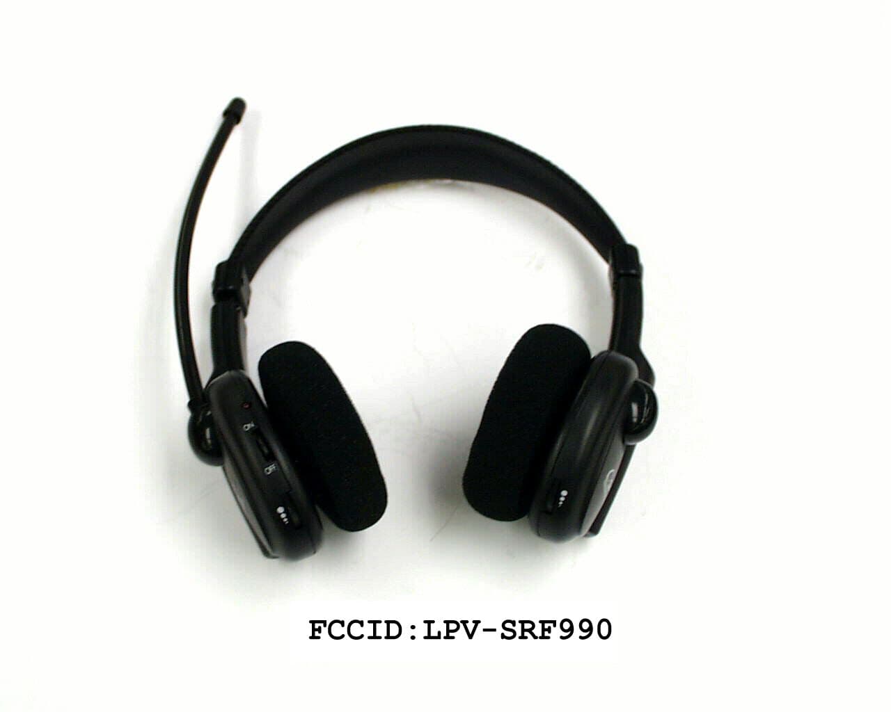
LPV-SRF990
Feb 07, 2000VHF Cordless Headphone System
Equipment Class
CYY - Communications Receiver used w/Pt 15 TransmitterLPVMCB-2E
Nov 02, 1997Auditory Assistance Receiver
Equipment Class
CYY - Communications Receiver used w/Pt 15 TransmitterLPVMCR-2E
Nov 02, 1997Auditory Assistance Receiver
Equipment Class
CYY - Communications Receiver used w/Pt 15 Transmitter