LTFIBR1
Ora Electronics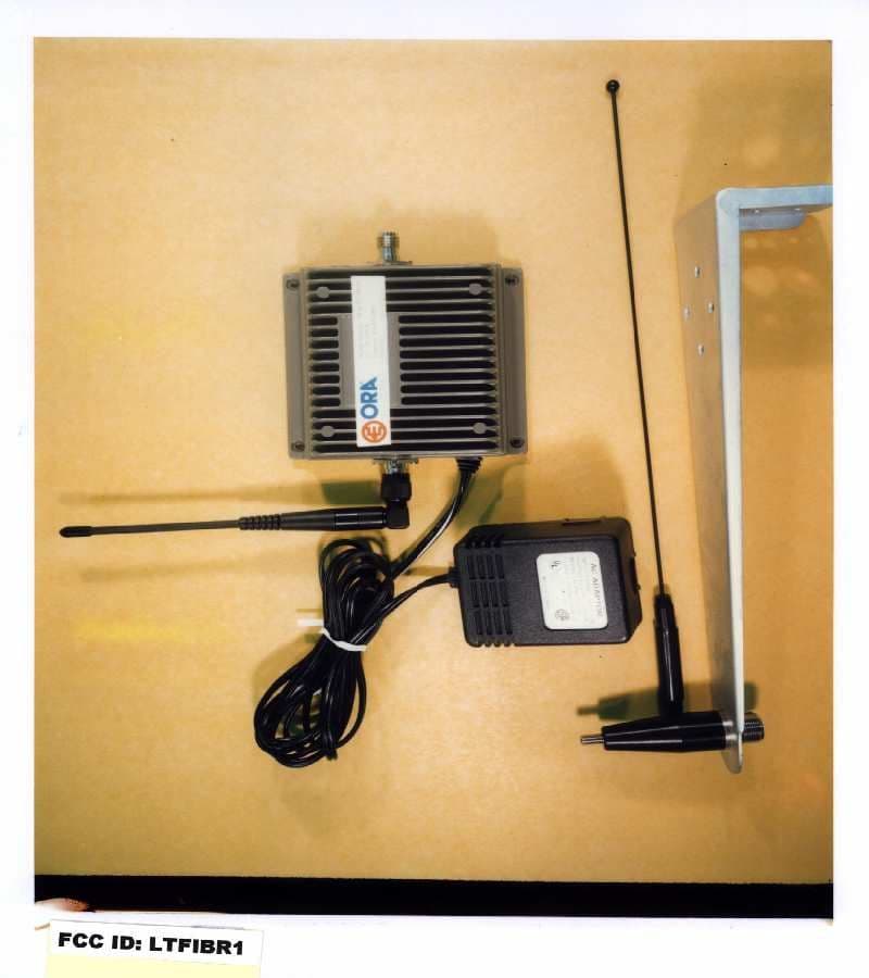
Click to zoom
Application Details
- Equipment Class
- AMP - Amplifier
- Date of Grant
- Aug 15, 1999
- Application Purpose
- Original Equipment
- Date of Application
- Apr 21, 1999
- Frequency Range
- 851.00000000 - 866.00000000
- Company
- Ora Electronics
- Country
- United States
Documents & Files
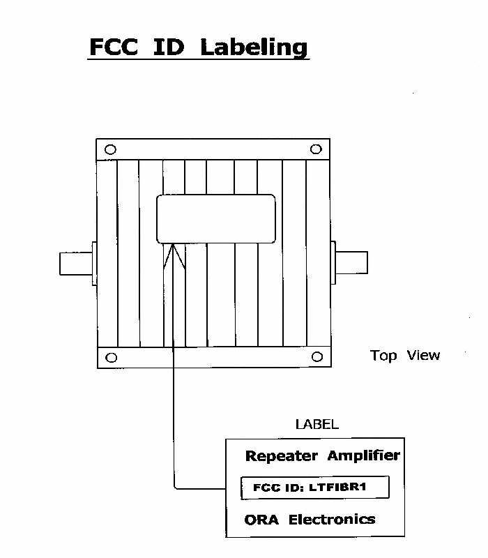
Document Text
Text extracted from the exhibit documents filed with the FCC. Open a document above to read the original.
Users Manual
USER'S GUIDE FOR THE Repeater Amplifier Model: IDR 3000 (ORA Logo) LEGAL The information provided herein by ORA Electronics, Inc. is believed to be complete and accurate. However, no responsibility is assumed by ORA Electronics, Inc. for any business or personal losses arising from its use, nor for any infringements of patents or other rights of third parties which may result from its use. ORA Electronics, Inc. reserves the right to change this unit’s specifications at anytime without notice. FCC ID: Frequency: Uplink: 806-821 MHz; Downlink: 851-866 MHz TRADEMARKS Throughout this User’s Guide, trade names and trademarks of some companies or products may appear. This is not intended to convey endorsement of, or other affiliation with ORA Electronics, Inc. or its products. This Repeater Amplifier contains proprietary software that is protected under the copyright laws of the United States of America and other countries. Copyright © 1999 ORA Electronics, Inc. All rights reserved. 1. PACKAGE CHECKLIST The Repeater Amplifier contains the following components: 1.1 Repeater Amplifier 1.2 AC-to-DC Transformer 1.3 User’s Guide 2. OPTIOAL ACCESSORIES 2.1 6-elements YAGI Antenna (As the Outdoor Antenna) 2.2 Monopole Omni Antenna (As the Indoor Antenna) 2.3 50-ohms Coaxial Cable CAUTION: The Repeater Amplifier is designed to work only with Motorola iDEN telephones. Other wireless telephones, including AMPS cellular phones will not work. No attempt to connect other phones to the amplifier should be made. 50-ohms Coaxial Cable 6-elements YAGI Antenna Repeater Amplifier AC-to-DC Transformer Monopole Omni Antenna 3. ABOUT THE REPEATER AMPLIFIER Thank you for purchasing the Repeater Amplifier from ORA Electronics, a leader in cellular and PCS accessories and enhancement products. The Repeater Amplifier markedly improves the signal quality when using your portable iDEN phone inside the building. This product boosts the power of both the transmitting and receiving signals of an iDEN phone, while providing longer range and better access to the iDEN System. When using an iDEN phone in the building, The signal is received by the internal antenna and sent through the Repeater Amplifier, then transmitted to the nearest cellsite through the Outdoor antenna. NOTE: This product generates and uses radio frequency energy. Improper installation and use not in strict accordance with the manufacturer’s instructions may cause interference with your reception. There is no guarantee given against interference in any particular installation. 4. INSTALLING THE REPEATER AMPLIFIER 4.1 Installing illustration 4.2 Installing the Outdoor Antenna 4.2.1 Select a good location for the Outdoor Antenna on the roof. You can use your iDEN phone to determine what place has the most signal strength. A suitable location must have the following requirements: ! The signal strength displayed on the iDEN phone must be a scale of 2 or more. ! You can call out successfully three times succession. 4.2.2 Set up the Outdoor Antenna. If a YAGI Antenna is used, point it toward a iDEN Base Station Coaxial cable Repeater Amplifier Indoor Antenna AC-to-DC Transformer Outdoor Antenna WARNING: ! The Outdoor Antenna should be placed at a minimum distance of 12 inches away from any people or children. ! In order to avoid interference, the Outdoor Antenna must not be close to any of the following: i. Other radio transmitting antenna. ii. High voltage power lines. iii. High voltage transformer. iv. Metal window or wall. ! If the installed Outdoor Antenna is in danger of being hit by lightning, a lightning rod should be added for protection. 4.3 Installing the Repeater Amplifier 4.3.1 Attach the Indoor Antenna to the Repeater Amplifier connector marked " PHONE ". 4.3.2 Mount the Repeater Amplifier on the ceiling or on the wall. To find a suitable place in the indoor environment, there are two requirements for selecting a good location. ! The Repeater Amplifier should be at least 10 feet from the ground. ! The Repeater Amplifier should be placed in the weak signal area. Do not place it far from the weak signal area. 4.3.3 Guild the direction of the Indoor Antenna toward the weak signal area. WARNING: ! The Indoor Antenna should be placed at a minimum distance of 12 inches away from any people or children. 4.4 Connecting the Repeater Amplifier and the Outdoor Antenna 4.4.1 Connect the Coaxial Cable from the Outdoor Antenna to the Repeater Amplifier connector marked " ANT ". 4.4.2 Fasten the Coaxial Cable on the wall securely preventing any damage from the wind. 4.5 Connecting the power 4.5.1 Connect the output connector of AC-to-DC Transformer to the "DC 12V IN" socket of the Repeater Amplifier. 4.5.2 Attach the plug of the AC-to-DC Transformer to the wall socket. The " POWER " indicator on the Repeater Amplifier will light up. 4.6 Testing Test each corner of interior with your iDEN phone. 5. TROUBLESHOOTING In the event of communications difficulty, check the following before seeking Technical Support: • Is the " POWER " indicator lit, showing that the power supply is connected? " Check if the power connector is loose. • Is the receiving scale on the iDEN phone too low to make a call? " Check if the connectors between the Indoor Antenna and the Outdoor Antenna are loose. • Is the receiving scale on the iDEN phone adequate but can not make a call? " The Repeater Amplifier might oscillate itself. Please increase the distance between the Outdoor Antenna and the Indoor Antenna. The Distance should be at least 3 feet. 6. SPECIAL APPLICATION In large areas like a department store, parking lot or hotel, one Repeater Amplifier may not be sufficient and several or many Repeater Amplifier units or a High Gain Repeater Amplifier may be necessary. In such cases, contact your dealer for larger area coverage solution. CAUTION Applying power may damage to this device if the Outdoor Antenna and Indoor Antenna are not connected properly.
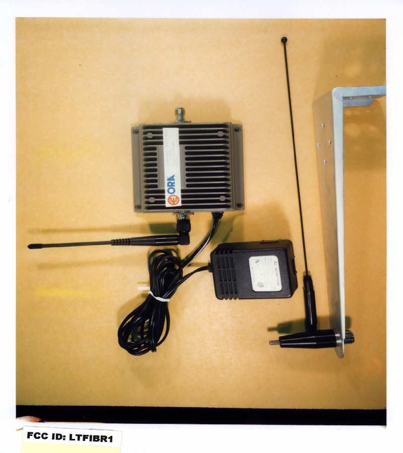
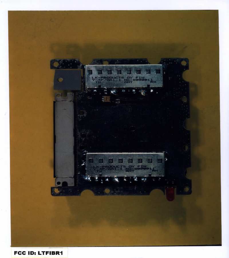
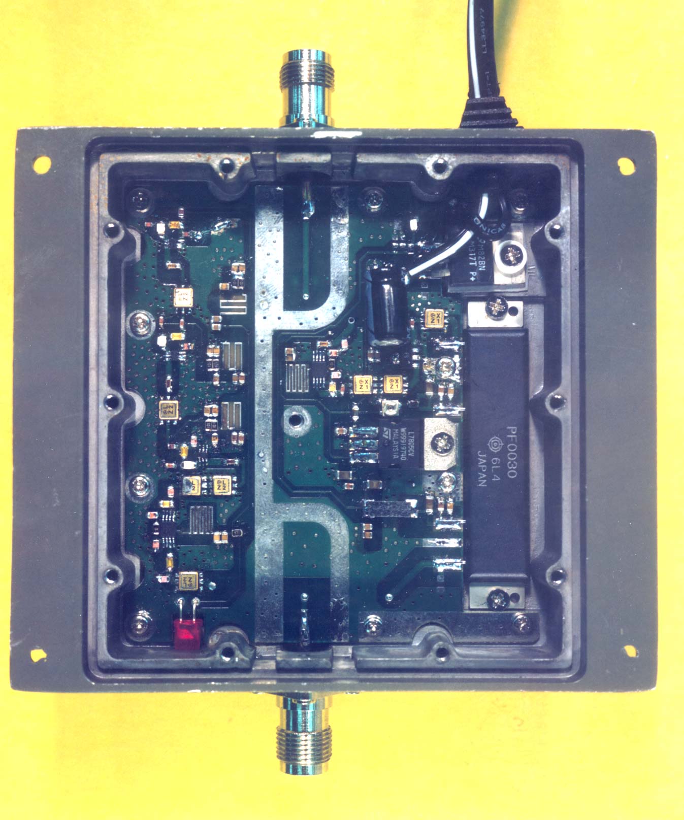
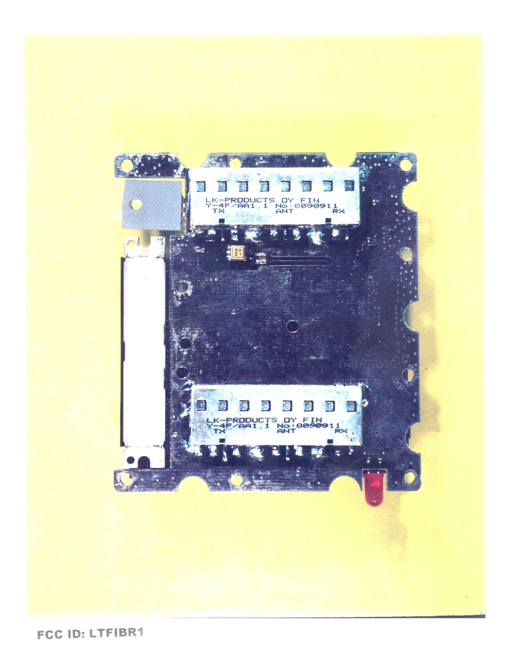
Internal Photos
SOLDER SIDE PHOTO OF EUT
RF Exposure Info
Evaluation of Compliance with FCC-Specified Guidelines for Human Exposure to Radio Frequency Electromagnetic Fields on the IDEN Amplifier Model: IDR 3000 for ORA Electronics Date of Test: December 30, 1998 - March 18, 1999 Job # J98034397 Total No. of Pages Contained in this Report: 8 + data pages All services undertaken are subject to the following general policy: Reports are submitted for exclusive use of the client to whom they are addressed. Their significance is subject to the adequacy and representative character of the samples and to the comprehensiveness of the tests, examinations or surveys made. No quotations from reports or use of Intertek Testing Services’ name is permitted except as expressly authorized by Intertek Testing Services in writing. FCC 2.1091 & ANSI 95.1-1992 VERIFICATION OF COMPLIANCE No. J98034397 Verification is hereby issued to the named APPLICANT and is VALID ONLY for the equipment identified hereon for use under the rules and regulations listed below. Equipment Under Test:IDEN Amplifier Trade Name:ORA Model No.:IDR 3000 Serial No.:Not Labelled Applicant:ORA Electronics Contact:Mr. Matthew F. Jodziewicz Address:9410 Owensmouth Avenue Chatsworth, California 91313 Tel. number:(818) 772-2700 Fax number:(818) 718-8626 Applicable Regulation:FCC 2.1091 & ANSI C95.1:1992 Equipment Class:Uncontrolled Environments Date of Test:December 30, 1998 - March 18, 1999 We attest to the accuracy of this report: Xi-Ming YangC.K. Li Test EngineerEngineering Manager A 1365 Adams Court, Menlo Park, CA 94025 ORA Electronics, IDEN AmplifierDate of Test: December 30, 1998 - March 18, 1999 Report # J98034397 FCC 2.1091 & ANSI C95.1:1992 Table of Contents 1.0Introduction.........................................................1 2.0Description of Equipment..............................................1 3.0Test Summary.......................................................1 4.0System Test Configuration.............................................2 4.1Support Equipment..............................................2 4.2Block Diagram of Test Setup.......................................2 4.3Justification....................................................3 4.4Software Exercise Program........................................3 4.5Mode of Operation During Test.....................................3 4.6Modifications Required for Compliance...............................3 5.0Radiated Emissions...................................................4 5.1Radiated Emission Limits..........................................4 5.2Site Description and List of Test Equipment............................5 5.3Test Procedure.................................................5 5.4Field Strength Calculation.........................................5 5.5Configuration Photographs........................................6 5.6Test Data......................................................7 6.0Miscellaneous Information or Other Comments............................8 A 1365 Adams Court, Menlo Park, CA 94025 ORA Electronics, IDEN AmplifierDate of Test: December 30, 1998 - March 18, 1999 Report # J98034397 FCC 2.1091 & ANSI C95.1:19921 1.0Introduction This report is designed to show compliance with the FCC Part 2.1091 Radio Frequency Radiation Exposure Evaluation for mobile and unlicensed devices. The test procedures and limits, as described in American National Standards Institute C95.1-1992, were employed. A description of the product and operating configuration, the various provisions of the rules, the methods for determining compliance, and a detailed summary of the results are included within this test report. 2.0Description of Equipment The ORA Electronics Model IDR 3000 is a 2 watts RF IDEN amplifier used in the SMR Service in the frequency range from 806 to 821 MHZ. The amplifier is used with magnetic car antenna with the following specification: 1.Antenna Type: Monopole Omni 2.Frequency Range: 800- 870 MHZ 3.Gain: 0 dBi 4.VSWR: 2.0 3.0Test Summary The IDEN amplifier was tested by Intertek Testing Services as documented herein, and the energy emitted by the EUT was found to be below the recommended levels of Maximum Permissible Exposure for Uncontrolled Environments in FCC 1.1310 (ANSI C95.1:L 1992). Therefore, in reference to the limits set forth in FCC 1.1310 use of the equipment is deemed to be safe with respect to human exposure to Radio Frequency Electromagnetic Fields, when used in a normal fashion. Note: The IDEN amplifier was tested with the antenna having 0 dBi gain and the emitted power density was found 4.8 dB below the limit (at 0.2m distance). Therefore, the amplifier can be used with any antenna having the gain less than 4.8 dBi. A 1365 Adams Court, Menlo Park, CA 94025 ORA Electronics, IDEN AmplifierDate of Test: December 30, 1998 - March 18, 1999 Report # J98034397 FCC 2.1091 & ANSI C95.1:19922 4.0System Test Configuration 4.1Support Equipment Item #DescriptionModel No.Serial No. 1Antenna Research SignalPMM 3000N/A Generators 2Extech Power SupplyEP-3003N/A 4.2Block Diagram of Test Setup * = EUTS = Shielded; F = With Ferrite ** = No ferrites on video cableU = Unshielded A 1365 Adams Court, Menlo Park, CA 94025 ORA Electronics, IDEN AmplifierDate of Test: December 30, 1998 - March 18, 1999 Report # J98034397 FCC 2.1091 & ANSI C95.1:19923 4.3Justification The system was configured for testing in a typical fashion (as a customer would normally use it). 4.4Software Exercise Program No special software was used during the tests. 4.5Mode of Operation During Test Transmitting full power (2W). 4.6Modifications Required for Compliance The following modifications were installed during compliance testing in order to bring the product into compliance (Please note that this list does not include changes made specifically by Teledex Corporation prior to compliance testing): No modifications were installed by Intertek Testing Services. A 1365 Adams Court, Menlo Park, CA 94025 ORA Electronics, IDEN AmplifierDate of Test: D…
Text truncated - open the document above for the full version.
Schematics
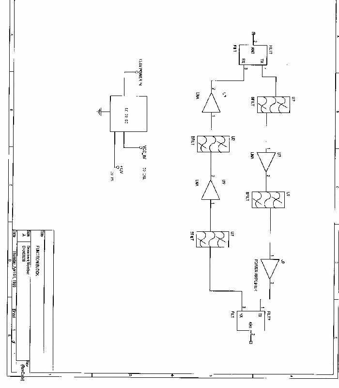
SCHEMATICS
Test Report
i Intertek Testing Services FCC Part 90 Certification Performed on the Repeater Amplifier FCC ID: LTFIBR1 Model: IDR 3000 for Ora Electronics Date of Test: December 30, 1998 - March 18, 1999 Job #: J98034397 Total No. of Pages Contained in this Report: 12 + data pages This report shall not be reproduced except in full, without written approval of Intertek Testing Services. This report must not be used to claim product endorsement by NVLAP or any agency of the U.S. Government. The results contained in this report were derived from measurements performed on the identified test samples. Any implied performance of other samples on this report is dependent on the representative of the samples tested. FCC Pt 90 cert, Rev. 8/98 Intertek Testing Services 1365 Adams Court, Menlo Park, CA 94025 Ora Electronics, Repeater AmplifierDate of Test: December 30, 1998 - March 18, 1999 FCC ID: LTFIBR1 ii Report # J98034397FCC Part 90 Type Acceptance Table of Contents 1.0Test Summary.......................................................1 1.1Product Description..............................................2 2.0RF Power Output.....................................................3 2.1Test Procedure..................................................3 2.2Test Equipment.................................................3 2.3Test Results....................................................3 3.0Effective Radiated Power..............................................4 3.1Test Procedure..................................................4 3.2Test Equipment.................................................4 3.3Test Results....................................................4 4.0Occupied Bandwidth, Bandwidth Limitation, Emission masks...................5 4.1Test Procedure..................................................5 4.2Test Equipment.................................................5 4.3Test Results....................................................5 5.0Out of Band Emissions at Antenna Terminals..............................6 5.1Test Procedure..................................................6 5.2Test Equipment.................................................6 5.3Test Results....................................................6 6.0Field Strength of Spurious Radiation.....................................7 6.1Test Procedure..................................................7 6.2Test Equipment.................................................7 6.3Test Results....................................................7 7.0Line Conducted Emissions.............................................8 7.1Test Procedure..................................................8 7.2Test Results....................................................8 8.0Frequency Stability vs Temperature......................................9 8.1Test Procedure..................................................9 8.2Test Equipment.................................................9 8.3Test Results....................................................9 9.0Frequency Stability vs Voltage.........................................10 9.1Test Procedure.................................................10 9.2Test Equipment................................................10 9.3Test Results...................................................10 Intertek Testing Services 1365 Adams Court, Menlo Park, CA 94025 Ora Electronics, Repeater AmplifierDate of Test: December 30, 1998 - March 18, 1999 FCC ID: LTFIBR1 iii Report # J98034397FCC Part 90 Type Acceptance 10.0Transient Frequency Behavior.........................................11 10.1Test Procedure.................................................11 10.2Test Result....................................................11 11.0List of Exhibits.....................................................12 Intertek Testing Services 1365 Adams Court, Menlo Park, CA 94025 Ora Electronics, Repeater AmplifierDate of Test: December 30, 1998 - March 18, 1999 FCC ID: LTFIBR1 1 Report # J98034397FCC Part 90 Type Acceptance 1.0Test Summary FCC RULEDESCRIPTION OF TESTRESULTPAGE 2.985RF Power OutputPass3 90.205Effective Radiated PowerPass4 2.989(I), 90.209(b)(5),Occupied Bandwidth, Bandwidth Limitation,Pass5 90.210Emission masks 2.991Spurious emissions at antenna terminalsPass6 2.993, 15.109Field Strength of Spurious RadiationPass7 15.107Line Conducted EmissionsPass8 2.995(a)Frequency Stability vs. TemperatureN/A9 2.995(d)(1)Frequency Stability vs. VoltageN/A10 2.914Transient frequency behaviorN/A11 Tested By: Xi-Ming YangDate Test Engineer Approved By: C.K. LiDate Engineering Manager Intertek Testing Services 1365 Adams Court, Menlo Park, CA 94025 Ora Electronics, Repeater AmplifierDate of Test: December 30, 1998 - March 18, 1999 FCC ID: LTFIBR1 2 Report # J98034397FCC Part 90 Type Acceptance 1.1Product Description The Ora Electronics Model IDR 3000 is a repeater amplifier designed to work with Motorola IDEN telephones. It boosts the power of both the transmitting and receiving signals of an IDEN phone, while providing longer range and better access to the IDEN system. Applicant and Mailing AddressOra Electronics 9410 Owensmouth Avenue Chatsworth, California 91311 Manufacturer and Mailing AddressSame FCC IDLTFIBR1 Use of ProductRepeater Amplifier Whether quantity (>1) production is [X] Yes, [ ] No planned Type(s) of EmissionFor this is a bi-direction amplifier, the type of emission depends on IDEN phone. Max. Allowed modulationNone Max. Allowed deviationNone Range of RF InputUplink: from -100 to -20 dBm Downlink: from -100 to -40 dBm The variation of operating power is determined by the input power level. The dc voltage applied to and current into the several elements of the finaldc 12 -1 5V, dc 1.5A RF amplifying device (V.A) Frequency RangeUplink: 806 - 821 MHz Downlink: 851-866 Max. number of ChannelsNone Antenna(e) & GainUplink Antenna: 6 dBi Downlink Antenna: 0 dBi Detachable antenna ?[X ]Yes, Connector Types:Uplink antenna: TNC Downlink antenna: TNC Receiver L.O. f…
Text truncated - open the document above for the full version.
Test Report
Exhibit 9.1 RF Power Output Plot NumberDescription 2.a.1Antenna In and Phone Out, Low Channel 2.a.2Antenna In and Phone Out, Middle Channel 2.a.3Antenna In and Phone Out, High Channel 2.a.4Phone In and Antenna Out, Low Channel 2.a.5Phone In and Antenna Out, Middle Channel 2.a.6Phone In and Antenna Out, High Channel
Test Report
Exhibit 9.2 Effective Radiated Power Test Data
Test Report
Exhibit 9.3 Occupied Bandwidth, Bandwidth Limitation Plot NumberDescription 4.3aInput FM, kHz DEV, 2.5 kHz AF, 851 MHz 4.3bOutput FM, 5 kHz DEV, 2.5 kHz AF, 851 MHz 4.3cInput FM, 5 kHz DEV, 2.5 kHz AF, 806 MHz 4.3dOutput FM, 5 kHz DEV, 2.5 kHz AF, 806 MHz 4.3eOutput, 806 MHz, IDEN, Full Power 4.3fOutput, 806 MHz, IDEN 100k span 4.3gOutput, 806 MHz, IDEN 200k span
Test Report
Exhibit 9.4 Spurious Emissions at Antenna Terminals Plots Plot #Description 5.3.aAntenna to Phone, 1 - 100 MHz, Low Channel 5.3.bAntenna to Phone, 100 - 1000 MHz, Low Channel 5.3.cAntenna to Phone, 1 - 2.5 GHz, Low Channel 5.3.dAntenna to Phone, 2.5 - 10 GHz, Low Channel 5.3.eAntenna to Phone, 1 - 100 MHz, Middle Channel 5.3.fAntenna to Phone, 100 - 1000 MHz, Middle Channel 5.3.gAntenna to Phone, 1 - 2.5 GHz, Middle Channel 5.3.hAntenna to Phone, 2.5 - 10 GHz, Middle Channel 5.3.iAntenna to Phone, 1 - 100 MHz, High Channel 5.3.jAntenna to Phone, 100 - 1000 MHz, High Channel 5.3.kAntenna to Phone, 1 - 2.5 GHz, High Channel 5.3.lAntenna to Phone, 2.5 - 10 GHz, High Channel 5.3.mPhone to Antenna, 1 - 100 MHz, Low Channel 5.3.nPhone to Antenna, 100 - 1000 MHz, Low Channel 5.3.oPhone to Antenna, 1 - 2.5 GHz, Low Channel 5.3.pPhone to Antenna, 2.5 - 10 GHz, Low Channel 5.3.qPhone to Antenna, 1 - 100 MHz, Middle Channel 5.3.rPhone to Antenna, 100 - 1000 MHz, Middle Channel 5.3.sPhone to Antenna, 1 - 2.5 GHz, Middle Channel 5.3.tPhone to Antenna, 2.5 - 10 GHz, Middle Channel 5.3.uPhone to Antenna, 1 - 100 MHz, High Channel 5.3.vPhone to Antenna, 100 - 1000 MHz, High Channel 5.3.wPhone to Antenna, 1 - 2.5 GHz, High Channel 5.3.xPhone to Antenna, 2.5 - 10 GHz, High Channel
Test Report
Exhibit 9.5 Field Strength of Spurious Radiation Test Data
Test Report
Exhibit 9.6 Line Conducted Test Data & Plots 17 Mar 1999 19:01:24 3. FCC CFR 47, Pt. 15 3.1 FCC, PT 15 - AC LINE CONDUCTED ORA ELECTRONICS M/N: IDEN REPEATER LINE [ ], LINE 2 [X] PEAKS FOUND ABOVE 38 dBuV PEAK #FREQ (MHz)AMPL (dBuV) 1.986147.1 21.02847.4 31.07747.2 42.07245.0 52.79142.5 63.32838.9 17 Mar 1999 18:44:29 3. FCC CFR 47, Pt. 15 3.1 FCC, PT 15 - AC LINE CONDUCTED ORA ELECTRONICS M/N: IDEN REPEATER LINE [X], LINE 2 [ ] PEAKS FOUND ABOVE 38 dBuV PEAK #FREQ (MHz)AMPL (dBuV) 1.906838.0 21.24240.6 31.55142.2
Test Setup Photos
TEST CONFIGURATION SETUP (RADIATED) TEST CONFIGURATION SETUP (LINE CONDUCTED)
Contact Information
Applicant
Matthew Jodziewicz
Technical Contact
Intertek Testing ServicesC.K. Li
(650) 463-2900
1365 Adams Court · Menlo Park, California · United States
Non-Technical Contact
Ora ElectronicsMatthew Jodziewicz
(818) 772-2700
Test Firm
Intertek Testing Services NA Inc.John Quigley
Technical Specifications
| # | Rule Parts | Frequency Range | Power Output | Emission |
|---|---|---|---|---|
| 2 | 9 | 851 MHz - 866 MHz | 30.00 mW | BOOSTER |
Other Applications from Ora Electronics
LTFCBI
Jan 26, 1999iDEN Booster
Equipment Class
AMP - AmplifierLTFURX1
Nov 12, 1997CRR - Superregenerative Receiver
Equipment Class
CRR - Superregenerative ReceiverLTFUTX1
Nov 11, 1997Remote Control for Automobile Cellular System
Equipment Class
DSC - Part 15 Security/Remote Control TransmitterLTFCB
Jan 23, 1995TNB - Licensed Non-Broadcast Station Transmitter
Equipment Class
TNB - Licensed Non-Broadcast Station TransmitterLTFARA
Dec 13, 1994The power output per-channel decreases with multi-channel loading.
Equipment Class
TNB - Licensed Non-Broadcast Station Transmitter