LTQ31121678Remote Keyless Entry Transceiver 315 MHz
Aptiv Services Deutschland GmbH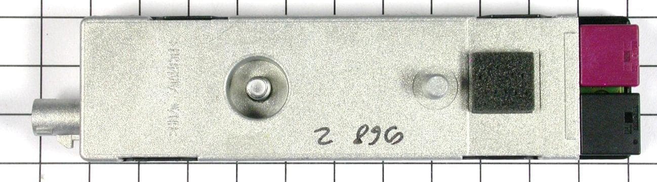
Click to zoom
Application Details
- Equipment Class
- DSR - Part 15 Remote Control/Security Device Transceiver
- Date of Grant
- Sep 05, 2012
- Application Purpose
- Original Equipment
- Date of Application
- Sep 05, 2012
- Equipment Note
- Remote Keyless Entry Transceiver 315 MHz
- Frequency Range
- 314.00000000 - 314.90000000
- Country
- Germany
Documents & Files
Document Text
Text extracted from the exhibit documents filed with the FCC. Open a document above to read the original.
Users Manual
American Certification Body Inc. 6731 Whittier Ave, Suite C110 McLean, VA22101 Date: 27.08.2012 FCC ID: LTQ31121678 IC: 3659A-31121678 Subject: Compliance Statement in Car Manual Dear Sirs, Our client’s products with the above listed product identification(s) are marketed together with cars, where it’s operation is included in the individual owner’s manual of the car. We hereby assure that the following caution statement as per CFR 47, §15.21 is included in a prominent location of the owner’s manual of the cars: The title “CAUTION TO USERS” or “FCC WARNING”: “NOTE” or relevant title and “Changes or modifications not expressly approved by the party responsible for compliance could void the user’s authority to operate the equipment.” In addition, we also assure that the following statement is also included in a prominent location in the manual as per CFR 47, §15.19(a)(3) and RSS-GEN 7.1.3: This device complies with Part 15 of the FCC Rules and Industry Canada license- exempt RSS standard(s). Operation is subject to the following two conditions: (1) this device may not cause harmful interference, and (2) this device must accept any interference received, including interference that may cause undesired operation In accordance with RSS-Gen Section 5.3 we assure that this statement will also appear in French. If you have any questions, please feel free to contact me at the address shown below. Yours sincerely, Christa Jäger Certification Group mikes-testingpartners gmbh Ohmstr. 2-4, 94342 Strasskirchen, Germany
Cover Letter(s)
Request for Confidentiality Date: 24.08.2012 Subject: Confidentiality Request for: FCC ID: LTQ31121678 IC: 3659A-31121678 ______ Pursuant to FCC 47 CRF 0.457(d) and 0.459 and IC RSP-100, Section 10, the applicant requests that a part of the subject FCC application be held confidential. Type of Confidentiality Requested Exhibit Short Term Permanent Block Diagrams Short Term External Photos Short Term Permanent* 1 Internal Photos Short Term Permanent Operation Description/Theory of Operation Short Term Permanent Parts List & Placement/BOM Short Term Permanent Tune-Up Procedure Short Term Permanent Schematics Short Term Test Setup Photos Short Term Permanent* User’s Manual *Note: ______(Insert Explanation as Necessary)______ Delphi Deutschland GmbH has spent substantial effort in developing this product and it is one of the first of its kind in industry. Having the subject information easily available to "competition" would negate the advantage they have achieved by developing this product. Not protecting the details of the design will result in financial hardship. Permanent Confidentiality: The applicant requests the exhibits listed above as permanently confidential be permanently withheld from public review due to materials that contain trade secrets and proprietary information not customarily released to the public. Short-Term Confidentiality: The applicant requests the exhibits selected above as short term confidential be withheld from public view for a period of (0) days from the date of the Grant of Equipment Authorization and prior to marketing. This is to avoid premature release of sensitive information prior to marketing or release of the product to the public. Applicant is also aware that they are responsible to notify ACB in the event information regarding the product or the product is made available to the public. ACB will then release the documents listed above for public disclosure pursuant to FCC Public Notice DA 04-1705. NOTE for Industry Canada Applications: The applicant understands that until such time that IC distinguishes between Short Term and Permanent Confidentiality, either type of marked exhibit above will simply be marked Confidential when submitted to IC. Sincerely, By: Manager Certification Thomas Ring 1 - The asterisked items (*) require further justification before permanent confidentiality will be allowed. These also currently require review by the FCC under their Permit-But-Ask policy before the grant is issued and can delay completion of an application. Further justification should be added to the note above. One such example for a potted device would be: “The EUT is FULLY potted using a non-removable epoxy based material. Removal of potting material causes irreparable damage to internal circuitry. See photographs exhibits that outline the device before and after potting.”
External Photos
FCC ID: WNS31121678 mikes-testingpartners gmbh File No. T36036-00-02HS, page 6 of 36 Ohmstrasse 2-4 94342 STRASSKIRCHEN GERMANY Tel.:+49(0)9424-94810 Fax: +49(0)9424-9481240 Rev. No. 1.2, 9.9.2010 3 E Q U I P M E N T U N D E R T E S T 3.1 Photo documentation of the EUT External view:
ID Label/Location Info
Label Location
Internal Photos
FCC ID: WNS31121678 mikes-testingpartners gmbh File No. T36036-00-02HS, page 7 of 36 Ohmstrasse 2-4 94342 STRASSKIRCHEN GERMANY Tel.:+49(0)9424-94810 Fax: +49(0)9424-9481240 Rev. No. 1.2, 9.9.2010 Internal view: FCC ID: WNS31121678 mikes-testingpartners gmbh File No. T36036-00-02HS, page 8 of 36 Ohmstrasse 2-4 94342 STRASSKIRCHEN GERMANY Tel.:+49(0)9424-94810 Fax: +49(0)9424-9481240 Rev. No. 1.2, 9.9.2010
Test Report
FCC ID: LTQ31121678 mikes-testingpartners gmbh File No. T36036-00-02HS, page 1 of 36 Ohmstrasse 2-4 94342 STRASSKIRCHEN GERMANY Tel.:+49(0)9424-94810 Fax: +49(0)9424-9481240 Rev. No. 1.2, 9.9.2010 EMI − T E S T R E P O R T - FCC Part 15.231 - Test Report No. : T36036-00-02HS 04. September 2012 ______________________________________________________________________________________________ Date of issue Type / Model Name : 3K FZV Product Description : Keyless entry system Applicant : Delphi Deutschland GmbH Address : TecCenter 31162 BAD SALZDETFURTH, GERMANY Manufacturer : Delphi Deutschland GmbH Address : TecCenter 31162 BAD SALZDETFURTH, GERMANY Licence holder : Delphi Deutschland GmbH Address : Delphiplatz 1 42119 WUPPERTAL, GERMANY Test Result according to the standards listed in clause 1 test standards: POSITIVE The test report merely corresponds to the test sample. It is not permitted to copy extracts of these test results without the written permission of the test laboratory. FCC ID: LTQ31121678 mikes-testingpartners gmbh File No. T36036-00-02HS, page 2 of 36 Ohmstrasse 2-4 94342 STRASSKIRCHEN GERMANY Tel.:+49(0)9424-94810 Fax: +49(0)9424-9481240 Rev. No. 1.2, 9.9.2010 Contents 1 T E S T S T A N D A R D S 3 2 S U M M A R Y 4 2.1 Test result summary 4 2.2 GENERAL REMARKS: 4 2.3 FINAL ASSESSMENT: 5 3 E Q U I P M E N T U N D E R T E S T 6 3.1 Photo documentation of the EUT 6 3.2 Power supply system utilised 10 3.3 Short description of the Equipment under Test (EUT) 10 4 T E S T E N V I R O N M E N T 11 4.1 Address of the test laboratory 11 4.2 Environmental conditions 11 4.3 Statement of the measurement uncertainty 11 4.1 Measurement protocol for FCC and IC 12 4.2 Determination of worst case measurement conditions 13 5 T E S T C O N D I T I O N S A N D R E S U L T S 14 5.1 Conducted emissions 14 5.2 Field strength of the fundamental wave 15 5.3 Spurious emissions (magnetic field) 9 kHz – 30 MHz 17 5.4 Spurious emissions radiated (electric field) 19 5.5 Correction for pulse operation (duty cycle) 24 5.6 Emission bandwidth 26 5.7 Frequency tolerance 31 5.8 Signal deactivation 33 6 USE D T E S T E Q U I P M E N T A N D A C C E S S O R I E S 36 FCC ID: LTQ31121678 mikes-testingpartners gmbh File No. T36036-00-02HS, page 3 of 36 Ohmstrasse 2-4 94342 STRASSKIRCHEN GERMANY Tel.:+49(0)9424-94810 Fax: +49(0)9424-9481240 Rev. No. 1.2, 9.9.2010 1 T E S T S T A N D A R D S The tests were performed according to following standards: FCC Rules and Regulations Part 15, Subpart A - General (September, 2011) Part 15, Subpart A, Section 15.31 Measurement standards Part 15, Subpart A, Section 15.33 Frequency range of radiated measurements Part 15, Subpart A, Section 15.35 Measurement detector functions and bandwidths FCC Rules and Regulations Part 15, Subpart C - Intentional Radiators (September, 2011) Part 15, Subpart C, Section 15.203 Antenna requirement Part 15, Subpart C, Section 15.204 External radio frequency power amplifiers and antenna modifications Part 15, Subpart C, Section 15.205 Restricted bands of operation Part 15, Subpart C, Section 15.207 Conducted limits Part 15, Subpart C, Section 15.209 Radiated emission limits, general requirements Part 15, Subpart C, Section 15.215 Additional provisions to the general radiated emission limitations Part 15, Subpart C, Section 15.231 Periodic operation in the band 40.66-40.70 MHz and above 70 MHz OET Bulletin 65, 65A, 65B, 65C Edition 97-01, August 1997 – Evaluating Compliance with FCC Guidelines for Human Exposure to Radio Frequency Electromagnetic Fields. ANSI C63.4: 2009 Methods of Measurement of Radio-Noise Emissions from Low- Voltage Electrical and Electronic Equipment in the Range of 9 kHz to 40 GHz. CISPR 16-4-2: 2003 Uncertainty in EMC measurement CISPR 22: 2005 Information technology equipment EN 55022: 2006 FCC ID: LTQ31121678 mikes-testingpartners gmbh File No. T36036-00-02HS, page 4 of 36 Ohmstrasse 2-4 94342 STRASSKIRCHEN GERMANY Tel.:+49(0)9424-94810 Fax: +49(0)9424-9481240 Rev. No. 1.2, 9.9.2010 2 S U M M A R Y 2.1 Test result summary SRD device using digital modulation: Operating in the 315 MHz band: FCC Rule Part RSS Rule Part Description Result 15.207(a) RSS Gen, 7.2.4. Conducted limits not applicable 15.231(b) RSS210, A1.1.2 Field strength of the fundamental wave passed 15.231(b) RSS210, A1.1.2 Spurious emissions (magnetic field) 9 kHz – 30 MHz passed 15.231(b) RSS210, A1.1.2 Spurious emissions radiated (electric field) passed 15.231(c) - Emission bandwidth passed 15.215(c) RSS-Gen, 7.2.6 Frequency tolerance passed 15.231(a1) RSS210, A1.1.1 Signal deactivation passed - RSS210, A1.1.3 OBW 99% passed The mentioned RSS Rule Parts in the above table are related to: RSS Gen, Issue 3, December 2010 RSS 210, Issue 8, December 2010 2.2 GENERAL REMARKS: This EUT is a transceiver for keyless entry systems for vehicular use. The EUT is a device with dedicated antenna. The antenna is realised as a special structure in the rear window of a car. The output power setting in the firmware is “34h” in a hex range from 4h to 40h. The user has no access on the output power setting of the device. Operation frequency and channel plan Channel Frequency 1 314.00 MHz 2 314.90 MHz 3 314.45 MHz Antenna Dedicated antenna, as a special structure in the rear window of a car. Transmit operating modes - Normal TX mode (when the car will be locked or unlocked) - Comfort TX mode (when the key is requested to open or close a window) FCC ID: LTQ31121678 mikes-testingpartners gmbh File No. T36036-00-02HS, page 5 of 36 Ohmstrasse 2-4 94342 STRASSKIRCHEN GERMANY Tel.:+49(0)9424-94810 Fax: +49(0)9424-9481240 Rev. No. 1.2, 9.9.2010 2.3 FINAL ASSESSMENT: The equipment under test fulfills the EMI requirements cited in clause 1 test standards. Date of receipt of test sample : acc. to storage records Testing commenced on : 4 June 2012 Testing concluded on : 12 June 2012 Checked by: Tested by: Thomas Weise Dipl. Ing.(FH) Laboratory Manager Hermann Sm…
Text truncated - open the document above for the full version.
Test Setup Photos
FCC ID: LTQ31121678 mikes-testingpartners gmbh File No. T36036-00-02HS, page 15 of 36 Ohmstrasse 2-4 94342 STRASSKIRCHEN GERMANY Tel.:+49(0)9424-94810 Fax: +49(0)9424-9481240 Rev. No. 1.2, 9.9.2010 5.2 Field strength of the fundamental wave For test instruments and accessories used see section 6 Part CPR 2. 5.2.1 Description of the test location Test location: OATS 1 Test distance: 3 m 5.2.2 Photo documentation of the test set-up 5.2.1 Applicable standard According to FCC Part 15C, Section 15.231(b): The field strength of emissions from intentional radiators shall not exceed the effective field strength limits. 5.2.2 Description of measurement The radiated field strength of the fundamental wave from the EUT is measured in the frequency range of 30 to 1000 MHz using a tuned receiver and appropriate broadband linearly polarized antennas. The setup of the EUT will be in accordance to ANSI C63.4. The EUT is measured in TX continuous mode unmodulated under normal conditions. EMI test receiver settings: 30 MHz – 1000 MHz: RBW: 120 kHz, Detector: Pk, FCC ID: LTQ31121678 mikes-testingpartners gmbh File No. T36036-00-02HS, page 17 of 36 Ohmstrasse 2-4 94342 STRASSKIRCHEN GERMANY Tel.:+49(0)9424-94810 Fax: +49(0)9424-9481240 Rev. No. 1.2, 9.9.2010 5.3 Spurious emissions (magnetic field) 9 kHz – 30 MHz For test instruments and accessories used see section 6 Part SER 1. 5.3.1 Description of the test location Test location: OATS 1 Test distance: 3 m 5.3.2 Photo documentation of the test set-up 5.3.3 Applicable standard According to FCC Part 15C, Section 15.209: The emissions from intentional radiators shall not exceed the effective field strength limits. 5.3.4 Description of measurement The magnetic field strength from the EUT will be measured on an open area test site in the frequency range of 9 kHz to 30 MHz using a tuned receiver and a shielded loop antenna. The set up of the Equipment under test will be in accordance to ANSI C63.4. The EUT is measured in TX continuous mode unmodulated under normal conditions. The resolution bandwidth during the measurement is as follows: 9 kHz – 150 kHz: RBW: 200 Hz 150 kHz – 30 MHz: RBW: 9 kHz FCC ID: LTQ31121678 mikes-testingpartners gmbh File No. T36036-00-02HS, page 19 of 36 Ohmstrasse 2-4 94342 STRASSKIRCHEN GERMANY Tel.:+49(0)9424-94810 Fax: +49(0)9424-9481240 Rev. No. 1.2, 9.9.2010 5.4 Spurious emissions radiated (electric field) For test instruments and accessories used see section 6 Part SER 2, SER 3. 5.4.1 Description of the test location Test location: OATS 1 Test location: Anechoic chamber 2 Test distance: 3 m 5.4.2 Photo documentation of the test set-up FCC ID: LTQ31121678 mikes-testingpartners gmbh File No. T36036-00-02HS, page 20 of 36 Ohmstrasse 2-4 94342 STRASSKIRCHEN GERMANY Tel.:+49(0)9424-94810 Fax: +49(0)9424-9481240 Rev. No. 1.2, 9.9.2010 5.4.3 Applicable standard According to FCC Part 15C, Section 15.231(b), Section 15.209(a) and Section 15.205(a): T he emissions from intentional radiators shall not exceed the effective field strength limits. 5.4.4 Description of measurement The radiated power of the spurious emission from the EUT is measured in a test setup following the procedures set out in ANSI C63.4. If the emission level of the EUT in peak mode complies with the average limit is 20 dB lower, then testing will be stopped and peak values of the EUT will be reported, otherwise the emission will be measured in average mode again and reported. Instrument settings: 30 MHz – 1000 MHz: RBW: 120 kHz 1000 MHz – 4000 MHz RBW: 1 MHz Example: Frequency Level + Factor = Level - Limit = Delta (MHz) (dBμV) (dB) dB(μV/m) dB(μV/m) (dB) 170.5 5 + 20 = 25 - 30 = -5 5.4.5 Test result f < 1 GHz No emissions could be detected within 20 dB to the limit at a test distance of 3 metres. Emissions 20 dB below the limit needs not to be reported. FCC ID: LTQ31121678 mikes-testingpartners gmbh File No. T36036-00-02HS, page 26 of 36 Ohmstrasse 2-4 94342 STRASSKIRCHEN GERMANY Tel.:+49(0)9424-94810 Fax: +49(0)9424-9481240 Rev. No. 1.2, 9.9.2010 5.6 Emission bandwidth For test instruments and accessories used see section 6 Part MB. 5.6.1 Description of the test location Test location: AREA4 5.6.2 Photo documentation of the test set-up 5.6.3 Applicable standard According to FCC Part 15C, Section 15.231(c): The bandwidth of the emission shall not exceed the effective limits. 5.6.4 Description of measurement The measurement was performed conducted with intentional modulation using a spectrum analyser. The analyser span was set wide enough to capture the most of the power envelope of the signal. The function “20-dB-down” is used to determine the BW. For an overview on the adjacent restricted bands the span was set as wide as needed to show that the restricted bands are not affected. Spectrum analyser setti ngs: RBW = 10 kHz, VBW = 30 kHz, Span: 200 kHz FCC ID: LTQ31121678 mikes-testingpartners gmbh File No. T36036-00-02HS, page 31 of 36 Ohmstrasse 2-4 94342 STRASSKIRCHEN GERMANY Tel.:+49(0)9424-94810 Fax: +49(0)9424-9481240 Rev. No. 1.2, 9.9.2010 5.7 Frequency tolerance For test instruments and accessories used see section 6 Part FE. 5.7.1 Description of the test location Test location: AREA4 5.7.2 Photo documentation of the test set-up 5.7.3 Applicable standard According to FCC Part 15C, Section 15.231(d): The frequency tolerance of the carrier signal shall be maintained within a limit of the operating frequency over extreme conditions for devices operating in the frequency range of 40.66 MHz – 40.70 MHz. 5.7.4 Description of Measurement The frequency tolerance is measured with the spectrum analyzer. The sweep points were set to maximum for higher the frequency resolution or the function “frequency counter” is used. The signal is unmodulated; the marker of the analyzer is set to maximum amplitude at normal temperature, the frequency was recorded. Than the maximum supply voltage is set and the marker of the analyzer is set to maximum amp…
Text truncated - open the document above for the full version.
Contact Information
Applicant
Ljiljana Trivic(Certification Responsible)
Technical Contact
Test Firm
CSA Group Bayern GmbHThomas Weise
Technical Specifications
| # | Rule Parts | Frequency Range | Power Output |
|---|---|---|---|
| 1 | 15.231 | 314 MHz - 314.9 MHz | - |
Other Applications from Aptiv Services Deutschland GmbH
LTQSRR6PH
Mar 09, 2026SRR6+
Equipment Class
VRD - Part 95 Vehicular Radar SystemsLTQSRR6PT
Jan 14, 2026Radar Sensor
Equipment Class
VRD - Part 95 Vehicular Radar SystemsLTQIHU42
Sep 05, 2024Infotainment Head Unit
Equipment Class
CXX - Communications Rcvr for use w/ licensed Tx and CBsLTQFLR7B
Jan 28, 2024Radar Sensor
Equipment Class
VRD - Part 95 Vehicular Radar Systems
LTQDHU1
May 05, 2023Display Head Unit
Equipment Class
DTS - Digital Transmission System