LW2RM25WM2.4GHz Wireless Hart Radio Module
Rosemount Inc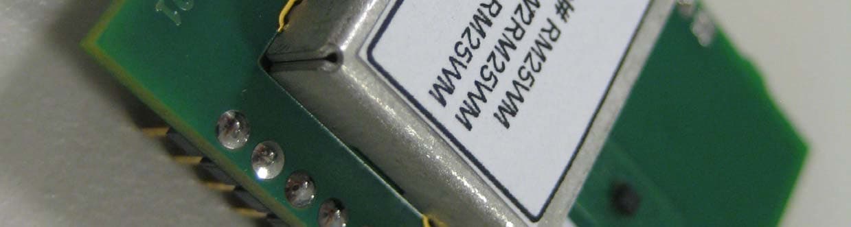
Click to zoom
Application Details
- Equipment Class
- DTS - Digital Transmission System
- Date of Grant
- Jan 02, 2014
- Application Purpose
- Original Equipment
- Date of Application
- Jan 02, 2014
- Equipment Note
- 2.4GHz Wireless Hart Radio Module
- Frequency Range
- 2400.00000000 - 2483.50000000
- Company
- Rosemount Inc
- Country
- United States
Documents & Files
Document Text
Text extracted from the exhibit documents filed with the FCC. Open a document above to read the original.
Cover Letter(s)
Letter of Agency I appoint Intertek Testing Services NA Inc. to act on our behalf in front of the Federal Communications Commission with respect to all matters relating to certification of equipment under the FCC rules until further notice. I further certify that no party (as defined in 1.2002 of CFR 47, 1995) to this application, including myself, is subject to denial of federal benefits, that includes FCC benefits, pursuant to Section 5301 of the Anti-Drug Abuse Act of 1988, 21 U.S.C.,853A. Equipment: Rosemount Wireless Radio Module Model RM25WM Dated this _29__day of October_, 2013. _ Signature Merritt Pulkrabek_______________________ Name Approvals Engineer_____________________ Title Rosemount Inc.________________________ Company 952.949.5193 _________________________ Telephone
Cover Letter(s)
Rosemount Inc. 8200 Market Boulevard Chanhassen, MN 55317 USA Attention: Application Examiner Re: Request for confidentiality Applicant: Rosemount, Inc. FCC ID: LW2RM25WM To whom it may concern, Permanent Confidentiality Request is hereby submitted by Rosemount, Inc. to withhold permanently from public review certain portions of the application for equipment certification for the referenced FCC identifiers. This request for confidentiality is made pursuant to 47 CFR 0.457(d) and 0.459 of the FCC Rules. In particular, the following sections of the application are to be kept permanently confidential: • Schematics • Detailed Block diagrams • Detailed Operational/Functional Description • Parts list • Internal photos • User Manual This device is a non-consumer device inaccessible to general public and is only accessable by qualified technical personnel in the industrial control industry. Short-term Confidentiality [Complete this section if short-term confidentiality is requested] Request is hereby submitted by Rosemount Inc. to withhold from public review for a period of 45 days from the date of the Grant of Equipment Authorization and prior to marketing, certain portions of the application for equipment certification for the referenced FCC identifiers. This request for confidentiality is made pursuant to 47 CFR 0.457(d) and 0.459 of the FCC Rules. In particular, the following sections of the application are to be kept confidential for a period of 45 days from the date of Authorization: • Test setup photos • External photos Rationale for request for confidentiality: Rosemount Inc. has invested considerable time and materials in research and development to produce the referenced product. Disclosure of the permanently confidential portions of this application to competitors would not only give them significant competitive advantages in developing similar products, but would also disclose successful implementation of unpublished, leading edge technology developed by us.: Disclosure of the short-term confidential portions of this application during the period of importation and/or distribution would reveal key aspects of proprietary technology to competitors and diminish the value of our investment in research and development. . The User Manual is only available to Rosemount business partners who have confidentiality agreements with us. Due to the detailed technical nature of the user manual it is considered confidential for the same reasons listed above. Sincerely, Principal Approvals Engineer Rosemount, Inc.
Cover Letter(s)
Rosemount Inc. 8200 Market Boulevard Chanhassen, MN 55317 USA Attention: Application Examiner Re: Justification of Modular Approval Applicant: Rosemount, Inc. FCC ID: LW2RM25WM To whom it may concern, Modular Transmitter Model RM25WM Request is hereby submitted by Rosemount, Inc. to certify the Wireless Hart Radio Module RM25WM as a Single Modular Transmitter under the applicable Industry Canada telecommunication rules. The following list shows compliance with each of the special requirements listed for modular approvals: • The Radio Elements must have the radio frequency circuitry shielded: The radio has a metal enclosure as can be seen in the photos • Buffered modulation/data inputs: The module uses the Linear Model DN2510 radio chip and it has buffered input and outputs • Power supply regulation: The module has DC power supply regulation as seen on the schematic • The module must contain a permanently attached antenna or contain a unique antenna connector: The module contains a MMCX connector that approved antennas can be connected. Since the module must be integrated into another enclosure, this connection is integral to the unit and not accessible to the end user. • Compliance in « Stand alone » configuration : This is demonstrated in the test report. • Permanent labeling : Per the module photos, the IC ID is permanently affixed to the module. • The module must comply with all specific rules applicable to the transmitter : See the test report and the user manual with the integration instructions. • RF exposure limits: See the test report. Sincerely, Principal Approvals Engineer Rosemount, Inc.
RF Exposure Info
EMC Report No: 101369978MIN-001 FCC ID: LW2RM25WMIC ID: 2731A-RM25WM Page 66 of 84 3.6 RF Exposure Compliance For 2 dBi Antenna: The maximum measured antenna conducted power, P is 9.56dBm The antenna gain, G is 2.0dBi The maximum EIRP power = P + G ERP = 9.56+2.0= 11.56dBm, or 0.01432W=14.32mW The limits for Maximum Permissible Exposure (MPE) for transmitter operating at 2.4Hz, MPE is 1mW/cm 2 , or 10W/m 2 S = 10W/m 2 The Power Density is related to EIRP with the equation: S = EIRP / 4πD 2 , or 10 = 0.01432 / 4πD 2 , where D is a separation distance The minimum safe separation distance, D = 1.06cm, which is below 20cm For 8 dBi Antenna: The maximum measured antenna conducted power, P is 9.56dBm The antenna gain, G is 8.0dBi The maximum EIRP power = P + G ERP = 9.56+8.0= 17.56dBm, or 0.05702W=57.02mW The limits for Maximum Permissible Exposure (MPE) for transmitter operating at 2.4Hz, MPE is 1mW/cm 2 , or 10W/m 2 S = 10W/m 2 The Power Density is related to EIRP with the equation: S = EIRP / 4πD 2 , or 10 = 0.05702 / 4πD 2 , where D is a separation distance The minimum safe separation distance, D = 2.13cm, which is below 20cm
Test Report
TEST REPORT Report Number: 101369978MIN-001 Project Number: G101369978 Testing performed on the RM25WM FCC ID: LW2RM25WM Industry Canada ID: 2731A-RM25WM to 47 CFR Part 15. 247:2010 RSS- 210, Issue 8, 2010 RSS-Gen, Issue 3, 2010 47 CFR, Part 15:2010, §15.107 and §15.109, Class B / ICES-003, Issue 5:2012 For Emerson Process Management Test Performed by: Test Authorized by: Intertek Testing Services NA, Inc. 7250 Hudson Blvd., Suite 100 Oakdale, MN 55128 USA Emerson Process Management 8200 Market Blvd. Chanhassen, MN 55317 USA Prepared by: Date: October 29, 2013 Simon Khazon Reviewed by: Date: October 29, 2013 Richard Blonigen This report is for the exclusive use of Intertek's Client and is provided pursuant to the agreement between Intertek and its Client. Intertek's responsibility and liability are limited to the terms and conditions of the agreement. Intertek assumes no liability to any party, other than to the Client in accordance with the agreement, for any loss, expense or damage occasioned by the use of this report. Only the Client is authorized to permit copying or distribution of this report and then only in its entirety. Any use of the Intertek name or one of its marks for the sale or advertisement of the tested material, product or service must first be approved in writing by Intertek. The observations and test results in this report are relevant only to the sample tested. This report by itself does not imply that the material, product, or service is or has ever been under an Intertek certification program. EMC Report No: 101369978MIN-001 FCC ID: LW2RM25WMIC ID: 2731A-RM25WM Page 2 of 84 TABLE OF CONTENTS 1.0 GENERAL DESCRIPTION..........................................................................................................3 1.1 Product Description; Test Facility......................................................................................4 1.3 Environmental conditions ..................................................................................................5 1.4 Measurement uncertainty..................................................................................................6 1.5 Field Strength Calculation .................................................................................................6 2.0 TEST SUMMARY..........................................................................................................................7 3.0 TEST CONDITIONS AND RESULTS........................................................................................8 3.1 6dB Emission bandwidth (EBW) of the digital modulation ................................................8 3.1.1 Emission bandwidth (EBW) of the digital modulation....................................................12 3.2 Maximum peak output power ..........................................................................................16 3.3 Power spectral density ....................................................................................................20 3.4 Antenna conducted spurious emissions..........................................................................24 3.4.1 Antenna conducted band edge compliance...................................................................34 3.5 Radiated spurious emissions ..........................................................................................37 3.6 RF Exposure Compliance ...............................................................................................66 3.7 Transmitter power line conducted emissions ..................................................................67 3.8 Receiver/digital device radiated emissions .....................................................................68 3.9 Digital device conducted emissions ................................................................................83 4.0 TEST EQUIPMENT.....................................................................................................................84 EMC Report No: 101369978MIN-001 FCC ID: LW2RM25WMIC ID: 2731A-RM25WM Page 3 of 84 1.0 GENERAL DESCRIPTION Model: RM25WM Type of EUT: 2.4GHz Wireless Radio Module FCC ID: LW2RM25WM Industry Canada ID: 2731A-RM25WM Related Submittal(s) Grants: None Company: Emerson Process Management Customer: Mr. Merritt Pulkrabek Address: 8200 Market Blvd. Chanhassen, MN 55317 USA Phone: (952) 949-5193 Fax: (952) 949-7626 e-mail: [email protected] Test Standards: 47 CFR, Part 15:2010, §15.247 RSS–210, Issue 8, 20010 RSS-Gen, Issue 3, 2010 47 CFR, Part 15:2010, §15.107 and §15.109, Class B ICES-003, Issue 5:2012 Other Type of radio: Stand -alone Module Hybrid Date Sample Submitted: October 17, 2013 Test Work Started: October 17, 2013 Test Work Completed: October 23, 2013 Test Sample Conditions: Damaged Poor (Usable) Good EMC Report No: 101369978MIN-001 FCC ID: LW2RM25WMIC ID: 2731A-RM25WM Page 4 of 84 1.1 Product Description; Test Facility Product Description: 2.4GHz Transceiver Module Transmitter Type: FHSS Digital Modulation WiFi Blue Tooth Operating Frequency Range(s): From 2400 to 2483.5 MHz Number of Channels: 15 (channels 0 to 14) Modulation: QPSK Emission Designator: 1M49G7D Antenna(s) Info: Antenna 1. Omni directional vertically polarized dipole Gain: 2 dBi Antenna 2. Omni directional vertically polarized dipole Gain: 8 dBi Power settings: 10 dBm Antenna Installation: User Professional Factory Transmitter power configuration: Internal battery External power source 120VAC 230VAC 400VAC 7.2 VDC Other: Amp. 50Hz 60Hz Special Test Arrangement: As a hand-held device the EUT was rotated through three orthogonal axes to determine and tested with the maximum emissions Test Facility Accreditation: A2LA (Certificate No. 1427.01) Test Methodology: Measurements performed according to the procedures in ANSI C63.10- 2009 and FCC 558074 D01 DTS Measurement Guidance EMC Report No: 101369978MIN-001 FCC ID: LW2RM25WMIC ID: 2731A-RM25WM Page 5 of 84 1.2 EUT Configuration The equipment un…
Text truncated - open the document above for the full version.
Test Setup Photos
Test Setup Photos
Contact Information
Applicant
Elizabeth Reierson(Sr. Quality Engineer)
Technical Contact
Rosemount Inc.Merritt O. Pulkrabek
[email protected]952-949-5193
8200 Market Blvd · Chanhassen · United States
Non-Technical Contact
Rosemount Inc.Robert J. Karschnia
[email protected]952-949-7552
Test Firm
Intertek Testing Services NA, Inc.Andrew Waytulonis
Technical Specifications
| # | Rule Parts | Frequency Range | Power Output |
|---|---|---|---|
| 1 | 15C | 2.40 GHz - 2.48 GHz | 10.00 mW |
Other Applications from Rosemount Inc

LW2-GEO20
Sep 21, 2020GEO20
Equipment Class
DTS - Digital Transmission System
LW2-GEO10
Sep 21, 2020GEO10
Equipment Class
DTS - Digital Transmission SystemLW2-781S58
May 31, 2020781SA
Equipment Class
DSS - Part 15 Spread Spectrum TransmitterLW2-248DX58
Mar 12, 2020248DX
Equipment Class
DTS - Digital Transmission SystemLW2-RMCT58
Feb 12, 20202051/3051
Equipment Class
DTS - Digital Transmission System