LYN20TX
Current Works Inc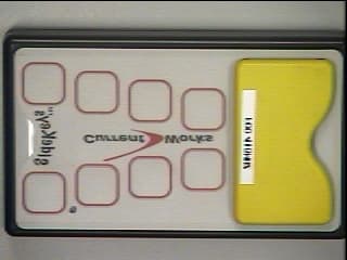
Click to zoom
Application Details
- Equipment Class
- DSC - Part 15 Security/Remote Control Transmitter
- Date of Grant
- Sep 27, 1998
- Application Purpose
- Original Equipment
- Date of Application
- Aug 12, 1998
- Frequency Range
- 418.00000000 - 418.00000000
- Company
- Current Works Inc
- Country
- United States
Documents & Files
Document Text
Text extracted from the exhibit documents filed with the FCC. Open a document above to read the original.
Users Manual
CWI SideKeys 3/9/981 SideKeys ™ Macintosh Version USER'S GUIDE Guaranty Your satisfaction is guarantied! If this product does not meet all of your expectations, you may return it, for any reason, within the first 90 days, for a complete money back guaranty. In Your Package In this SideKeys package you should have: • This SideKeys "User's Guide" • 1 SideKeys Receiver - for Macintosh • 3 SideKeys Transmitters with Inserts Installed • 3 Sheets of Blank Inserts • 3 Nine-volt alkaline batteries (for Transmitters) • 1 Copy of "SideKeys Teams in the Classroom" • 1 Product Registration Card Sales & Service To order additional Inserts, Transmitters, or other SideKeys compatible software products, call our Sales/Customer Service Representatives at: 1-888-526-1200 , or e-mail us at: [email protected] CWI SideKeys 3/9/982 The Group Interaction Tool SideKeys is a unique product that allows several teams to use a single computer simultaneously. SideKeys wireless transmitters send keystrokes to the computer from anywhere in the classroom. Radio frequency technology allows SideKeys to operate without line-of-sight requirements. Graphic of the Computer/Sidekeys RX/ 3 SideKeys TX The Features of Your SideKeys • All three transmitters can simultaneously input to one computer • There are nine independent keys on each transmitter • Each transmitter key can be defined as a unique computer keystroke • Keys on the transmitter can be labeled by changing the paper Inserts • Radio frequency transmitters have a range of 50 feet • Mac and PC/Windows versions of the Receiver available • No software to install; plug one cable into your computer and play! • Transmitters work with eother Mac or PC Receivers Installation of Receiver on the Macintosh Computer 1. Shutdown and turn off the computer. 2. Unplug the keyboard from the back of the computer. 3. Plug the SideKeys Receiver into this keyboard port on the back of the computer. 4. Plug the keyboard cable into the "Y" connector on the Receiver cable. 5. Turn on the computer. (The SideKeys Receiver must be installed correctly before the computer is turned on. The computer needs to identify the SideKeys receiver during the "Boot-up" process.) Set Up of Transmitters Install one, nine-volt battery in the rear battery case of each SideKeys Transmitter. Make sure the battery wires lay beside the battery, so that the access door snaps shut easily after installing the battery. Pre-Set Transmitters If you purchased SideKeys™ bundled with a specific software program, the transmitters are preset to match that software and the installed inserts. Just install the SideKeys Receiver and the bundled software on your computer and begin to play. To use SideKeys with other software, please use the following instructions. CWI SideKeys 3/9/983 Transmitter Inserts • Select the software you want to use and identify the keystrokes needed for the operations to be performed remotely from the SideKeys. • Create a new set of "key label" inserts for those "needed" keystrokes or, if available, use a preprinted insert. • Slide the previous inserts out of the Transmitter sleeves and slide these new inserts into place. Graphic of SideKeys TX with Insert sliding into place Defining or Re-Defining a Transmitter Key • Before you begin defining the transmitter keys, bring up a text based application, e.g. "Notepad" (a desk accessory, under the Apple, on Mac), "Simple Text" or other word processing program, on your computer. You will be able to test, on the monitor, how the keys are defined. • The following 3 steps are also printed on the front label of the Receiver. Graphic of SideKeys RX with label on front 1. Press and release the red button on the side of the Receiver. (The green LED light on the Receiver will light for 5 seconds) 2. Press the Transmitter key you wish to define, within 5 seconds. (The green LED light on the Receiver will blink for another 5 seconds.) 3. Press the corresponding key, or modified* key on the computer keyboard, within 5 seconds. *(key modifiers include: "shift", "option", "command", "control") (The green LED light will go off when the key is defined, or when the 5 seconds expires) • Test that newly defined key on the Transmitter to see that it does send the desired keystroke to the computer. • Define the next key as you did the first. Continue until as many keys as needed for your application are defined. • You can define more than one Transmitter to the Receiver for any application. The Receiver will only recognize Transmitter Keys that are specifically define to it. CWI SideKeys 3/9/984 NOTE: SideKeys will work on all Macintosh desktop and powerbook computers. However, on the Macintosh Powerbook-3400, the Transmitter Keys cannot be re-defined by the keyboard on this Powerbook. The SideKeys must be defined, as needed, on another computer before installing it on this Powerbook. An external keyboard can be connected to SideKeys and this Powerbook and used to re-define the Transmitter keys. NOTE: SideKeys may be used to emulate mouse functions. Consult your computer instructions for using the keyboard for mouse functions. Deleting or Clearing a Transmitter from a specific Receiver This is useful when using a transmitter within range of two receivers, but you only want one of the recivers to accept the signal. 1. Press and hold, for 5 seconds, the red button on the Receiver until the green LED light begins to blink rapidly, then release the button. (The green LED light continues to blink rapidly for 5 seconds) 2. Press one of the keys on the Transmitter you wish to delete or clear, within the 5 seconds. (The green LED light will blink slowly for 5 seconds) 3. Press the "Delete" key on the computer keyboard within 5 seconds. (The green LED light goes off) That specific Transmitter is cleared from that specific Receiver. Test it to make sure no signal is received. Cleaning SideKeys may be cleaned using a soft, clean cloth dampened with clean water or a plastic cleaner. S…
Text truncated - open the document above for the full version.
Cover Letter(s)
Page 1 of 1 FCC ID: LYN20TX Current Works, Inc. Description of SideKeys TM This device is a wireless transmitter of nine keys. The handheld keypad sends an RF signal to a matched receiver connected to the CPU of a personal computer. The receiver is connected to the computer between the computer’s normal keyboard and its CPU. The computer’s normal keyboard and mouse remain connected, active, and usable. There may be several remote SideKeys keypads matched to the same receiver, allowing several users to access one computer. The SideKeys transmitting keypads has nine individual switches. When a switch is pressed, the transmitter sends a fixed Wireless 418 MHz Modulated Radio Frequency signal to the matching receiver. This fixed signal indicates which transmitter is being used and on which one the individual switches was pressed. The signals sent are a finite number of predetermined codes, as in a remote control security device. These codes are sent one at time for a single, predetermined meaning, not strung together in different orders to get different meanings. They do not send data to the receiver. The receiver converts this fixed signal into the prescribed scan code signal and sends it on to the computer’s CPU to enter the desired keystroke. The SideKeys transmitting keypads are matched to the receiver and the individual keys are defined in the receiver by following the three simple steps described on the receiver.
External Photos
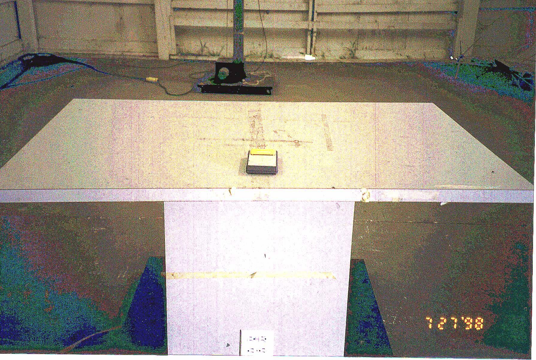
Page 1 of 1 FCC ID: LYN20TX Current Works, Inc. Top of EUT
ID Label/Location Info
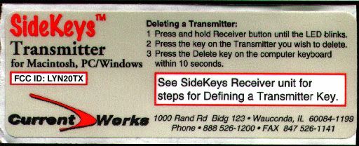
Page 1 of 2 Current Works, Inc. FCC ID: LYN20TX Page 2 of 2 The Label is Black, Pantone Red 032 CV and Cool Gray 3CV and white The label is 8.9 x 3.2 cm with permanent acrylic adhesive. The material is polyester. FCC Label
Internal Photos
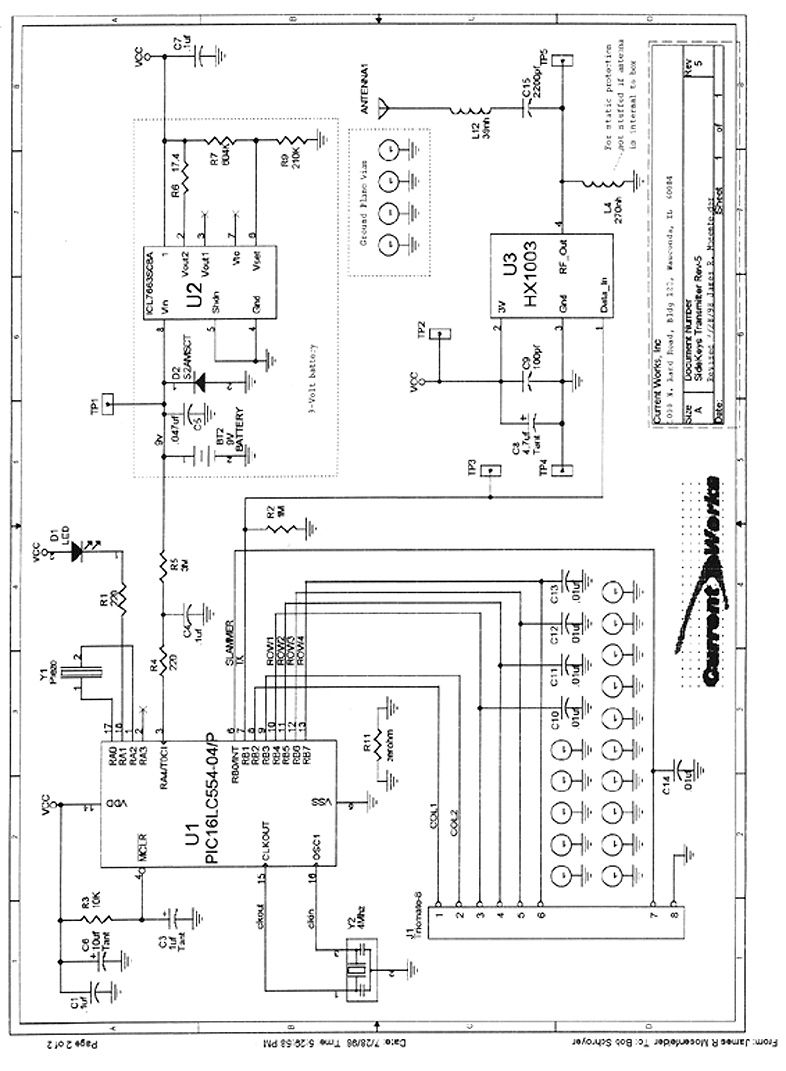
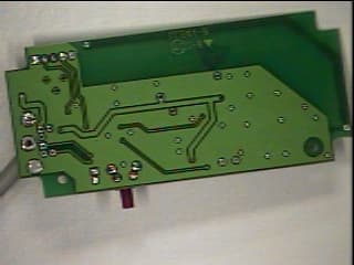
Page 1 of 2 FCC ID: LYN20TX Current Works, Inc. Foil Side of PCB Component Side of PCB Page 2 of 2 Component side of PCB with ribbon cable showing
Operational Description
Page 1 of 1 FCC ID: LYN20TX Current Works, Inc. Description of SideKeys TM This device is a wireless transmitter of nine keys. The handheld keypad sends an RF signal to a matched receiver connected to the CPU of a personal computer. The receiver is connected to the computer between the computer’s normal keyboard and its CPU. The computer’s normal keyboard and mouse remain connected, active, and usable. There may be several remote SideKeys keypads matched to the same receiver, allowing several users to access one computer. The SideKeys transmitting keypads has nine individual switches. When a switch is pressed, the transmitter sends a fixed Wireless 418 MHz Modulated Radio Frequency signal to the matching receiver. This fixed signal indicates which transmitter is being used and on which one the individual switches was pressed. The signals sent are a finite number of predetermined codes, as in a remote control security device. These codes are sent one at time for a single, predetermined meaning, not strung together in different orders to get different meanings. They do not send data to the receiver. The receiver converts this fixed signal into the prescribed scan code signal and sends it on to the computer’s CPU to enter the desired keystroke. The SideKeys transmitting keypads are matched to the receiver and the individual keys are defined in the receiver by following the three simple steps described on the receiver.
Operational Description
Detailed description of the information the transmitter is sending to the PC and what device is being controlled. The Transmitter is a set of nine manually operated switches. Each of these nine switches is programmed to send a fixed unique 'recognition code". as described here: The recognition code consists of a Start pulse plus 22 code bits: Bit Function 1"Guard" bit (always 0) 2-11Transmitter ID number (between 1 and 1023) 12Switch State (1 closed, O=open) 13“Togyle” (AIternates 1/0) 14-17Switch Number (between 1 and 9) 18-21Checksum 22"Guard" bit (always 0) • The "Guard" bits are always binary zeros and are used only to mark the beginning and end of the code word. • The transmitter ID is used to identify the specific transmitter being used. • The Switch state bit is "1" while the switch is being held closed manually and “0” when released and open. The transmitter continues to send the recognition code for only one second after the switch is released. • The Toggle bit alternates between a "1" and a "0" each time a switch is pressed an released. This permits detection when a switch is released and then pressed again, as compared to a switch that remained pressed. • The Switch Number indicates which of the nine switches on the transmitter is manually pressed. • The Checksum is calculated as the number of the binary “0” bits in the recognition code, excluding the checksum itself and the two Guard bits. This number is compared to the same calculation performed on the received code, if they are not equal the received code is rejected for containing errors. This is the only code that is sent and it is fixed for each switch on each transmitter. The transmitter does not measure or collect any data. The code transmitted only to identify which switch is manually activated. We believe that this Transmitter is operating pursuant to Section 15.231(a) of the Rules for the following reasons: • This Transmitter operates periodically @ 315MHz • The signal transmitted is a fixed "recognition code” identifying a specific remote switch that has been manually activated. • The manually operated transmitter automatically deactivates the transmitter at one second after the switch is released. • This Transmitter is Not used to control toys Not continuously transmitting voice, video or data Not activated automatically Not video transmitting at regular predetermined intervals Not used to signal an alarm This Transmitter directly interacts and controls the Sidekeys Receiver. This Receiver is a computer peripheral, connected between the personal computer's keyboard and its CPU. The Transmitter does not directly interact with the computer. It only sends a "recognition code" to the Receiver. The receiver accepts this recognition code, indicating that a specific switch has been pressed on the transmitter. This specific recognition code is defined, within the Receiver, to trigger a specific keyboard character scan code. This scan code is "learned" by the Receiver from the attached keyboard, also connected to the computer, through the Receiver. The Receiver sends the scan code associated with that keystroke into the CPU. The computer accepts and interprets this scan code as text characters or other keyboard characters, just as if it had been sent by the keyboard. The Transmitter, therefore, indirectly controls the computer, through the Receiver, by allowing for remote wireless input of keyboard characters into the personal computer. The Transmitter does not send data or even keyboard character scan codes directly into the computer.
Test Report
418 MHz transmitter Radiometrics Midwest Corporation Test Document RP-3806A Issue Date: August 14, 1998 This report concerns: Original grant Equipment type: Transmitter Transition Rules per 15.37 are not requested. Tests Performed ForTest Facility Current Works, Inc. 1000 N. Rand Rd, Bldg 115 Wauconda, Illinois 60084 Radiometrics Midwest Corporation 12 East Devonwood Romeoville, IL 60446 Phone: (815) 293-0772 FAX: (815) 293-0820 [email protected] Test Report Written ByTest Report Approved By Charles Grimes EMC Engineer Joseph Strzelecki Senior EMC Engineer NARTE EMC-000877-NE MEASUREMENT/TECHNICAL REPORT Current Works, Inc. Model SideKeys FCC ID: LYN20TX APPLICATION FOR CERTIFICATION RF Emission Measurements Performed For Determination of Compliance with the US Code of Federal Regulations Title 47, Chapter I, FCC Part 15 Subpart B As Required for Certification for Intentional Radiators Tests Performed ForFCC IDRadiometrics Test DocumentPage Current Works, Inc. LYN20TXRP-3806A2 of 10 Table of Contents 1.0 General Information ..................................................................................................................3 1.1 Product Description ...............................................................................................................3 1.2 Related Submittals ................................................................................................................3 1.4 Tested System Details...........................................................................................................3 1.5 Test Methodology ..................................................................................................................3 1.6 Test Facility............................................................................................................................4 1.7 Test Equipment .....................................................................................................................4 2.0 System Test Configuration........................................................................................................4 2.1 Test System and Justification ................................................................................................4 2.2 EUT Test Configuration ............................................................................................................4 2.3 Special Accessories...............................................................................................................4 2.4 Equipment Modifications........................................................................................................4 Figure 2.1 Configuration of Tested System .................................................................................5 3.0 Occupied Bandwidth Data ........................................................................................................6 Figure 3.1 Occupied Bandwidth Plot ...........................................................................................7 4.0 Peak to Average Calculations ...................................................................................................8 5.0 Radiated Emissions Data..........................................................................................................9 5.1 Field Strength Calculation....................................................................................................10 Notice: This report must not be reproduced (except in full) without the written approval of Radiometrics Midwest Corporation. Tests Performed ForFCC IDRadiometrics Test DocumentPage Current Works, Inc. LYN20TXRP-3806A3 of 10 1.0 General Information 1.1 Product Description The Model SideKeys (referred to as the EUT in this report) is a 418 MHz transmitter. The EUT is manufactured by Current Works, Inc. The EUT is a wireless transmitter of nine keys. The handheld keypad sends an RF signal to a matched receiver connected to the CPU of a personal computer. The receiver is connected to the computer between the computer’s normal keyboard and its CPU. The computer’s normal keyboard and mouse remain connected, active, and usable. There may be several remote SideKeys keypads matched to the same receiver, allowing several users to access one computer Each of the SideKeys transmitting keypads has nine individual switches. When a switch is pressed, the transmitter sends a fixed Wireless 418 MHz Modulated Radio Frequency signal to the matching receiver. This fixed signal indicates which transmitter is being used and on which one the individual switches was pressed. The signals sent are a finite number of predetermined codes, as in a remote control security device. These codes are sent one at time for a single, predetermined meaning, not strung together in different orders to get different meanings. They do not send data to the receiver. The receiver converts this fixed signal into the prescribed scan code signal and sends it on to the computer’s CPU to enter the desired keystroke. The SideKeys transmitting keypads are matched to the receiver and the individual keys are defined in the receiver by following the three simple steps described on the receiver. 1.2 Related Submittals The associated receiver is operated under Part 15 Subpart B. It is subject to the FCC requirements pursuant to the Certification equipment authorization under Part 15 Subpart C, and is being submitted as FCC ID: LYN48RX. 1.4 Tested System Details The FCC ID's for all equipment, plus descriptions of all cables used in the tested system which have grants, are: Model Number Serial NumberFCC ID Manufacturer & Description Cable Descriptions M/N: SideKeys (EUT) S/N: LYN20TXCurrent Works, Inc. 418 MHz transmitter none 1.5 Test Methodology The test procedures used are in accordance with the ANSI document C63.4-1992, (July 17, 1992) "Methods of Measurement of Radio Noise Emissions from Low-Voltage Electrical and Electronic Equipment in the Range of 9 kHz …
Text truncated - open the document above for the full version.
Contact Information
Applicant
Robert L Schroyer(President)
847 526-1121
Technical Contact
Radiometrics Midwest CorporationJoseph R Strzelecki
[email protected]815-293-0772
12 East Devonwood Av. · Romeoville, Illinois · United States
Non-Technical Contact
Radiometrics Midwest CorporationJoan E Strzelecki
[email protected]815-293-0772
Technical Specifications
| # | Rule Parts | Frequency Range | Power Output | Tolerance |
|---|---|---|---|---|
| 1 | 15C | 418 MHz - 418 MHz | - | % |
Other Applications from Current Works Inc
LYN48RX
Sep 21, 1998JBP - Part 15 Class B Computing Device Peripheral
Equipment Class
JBP - Part 15 Class B Computing Device PeripheralLYN46RX
Feb 09, 1998JBP - Part 15 Class B Computing Device Peripheral
Equipment Class
JBP - Part 15 Class B Computing Device PeripheralLYN26TX
Feb 09, 1998DSC - Part 15 Security/Remote Control Transmitter
Equipment Class
DSC - Part 15 Security/Remote Control TransmitterLYN11TX
Mar 18, 1996Emergency Light Test Transmitter
Equipment Class
CYY - Communications Receiver used w/Pt 15 TransmitterLYN22RX
Mar 18, 1996Energency Light Test Receiver
Equipment Class
CYY - Communications Receiver used w/Pt 15 Transmitter