M2HP03Transmitter Standard-433
Lodar LTD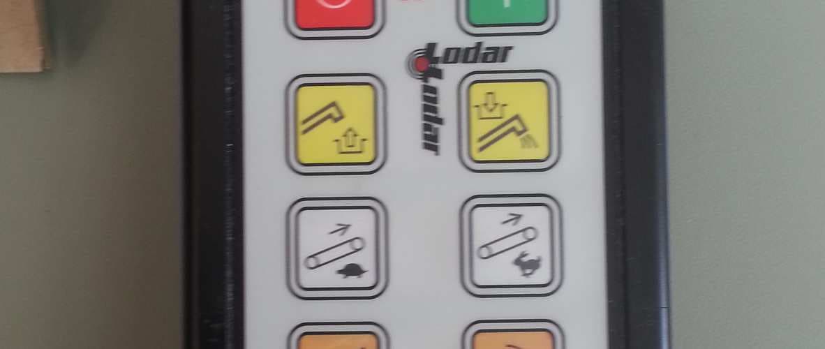
Click to zoom
Application Details
- Equipment Class
- DSC - Part 15 Security/Remote Control Transmitter
- Date of Grant
- Aug 19, 2014
- Application Purpose
- Original Equipment
- Date of Application
- Aug 19, 2014
- Equipment Note
- Transmitter Standard-433
- Frequency Range
- 433.90000000 - 433.90000000
- Company
- Lodar LTD
- Country
- United Kingdom
Documents & Files
Document Text
Text extracted from the exhibit documents filed with the FCC. Open a document above to read the original.
Users Manual
2 or Disconnect Battery IDENTIFY POWER CONNECTION POINT AND ISOLATE SUPPLY Fuse Remove fuse Vehicle batteries contain gasses which are flammable and explosive. Wear eye protection and do not lean over battery while disconnecting. Do ! WARNING 1. The Receiver is designed to carry a maximum of 15 Amps. That is, for example,15 Amps through one output or 5 Amps each through 3 outputs. 2.Master Output. This can be configured to Continuous or Parallel operation, see overleaf for details. 3.If Receiver outputs are connected in parallel with an external switching device (wired remote) the Receiver will instantly switch off when the wired remote is operated 4.Lodar Receivers have an isolation switch for safety, to allow for registering a MUST replacement Transmitter. 5.Safety Feature. Both the Transmitter and the Receiver will “time out” after 30 minutes of inactivity. This can be altered, ask your dealer. 1 ! BEFORE YOU START Wiring Instructions for 2 & 4 Function, 92 & 93 Series, FET Receivers. 92 02/4 RX & 93 02/4 RX have 7 core cable CONNECT WIRES 4 Transmitter Function Convention 92 00 RX & 93 00 RX have 4 core cable www.lodar.com 9000 F1 F2 F3 F4 5 or re-connect Battery ACTIVATE THE RECEIVER SUPPLY Fuse Replace fuse Press the Transmitter buttonRESET to activate the system, and carefully test each function for correct operation. 7 TEST 6 CONNECT TRANSMITTER BATTERY Batteries generally have to be disconnected when shipping. 3 Secure using 5mm (3/16") bolts (not supplied) through the 4 mounting feet TAKE TIME TO LOCATE THE BEST POSITION If necessary, power the Receiver and move it around the vehicle until the required performance is achieved. Operate the Transmitter and observe the Receiver internal LED’s. Mount as HIGH as possible AVOID surfaces with HEAVY VIBRATION AVOID DIRECT SPRAY from wheels In a HOT CLIMATE fit in a SHADED position Cable gland should face DOWN or BACK Receiver 92 04 RX and 93 04 RX shown, Waterproof to IP67, complete with 3 metres (10 ft) cables CAUTION MOUNT RECEIVER STOP POSITIVE NEGATIVE ! 12/24 Volts DC Nominal Positive Supply RED Negative BLACK GREEN YELLOW BROWN BLUE WHITE Output Function 1 Output Function 2 Output Function 3 Output Function 4 Output Function Master Wire used for Wire Colour Not Present Not Present Not Present Not Used Not Used 9200RX and 9300RX 9202RX and 9302RX 9204RX and 9304RX Make notes about the connections made in the boxes below What is the MASTER Output for ? It is used to operate the pump of an electro-hydraulic power pack or maybe a clutch pump. It can also be used for powering a dump valve, master valve etc. It can be configured to work continuously, that is ON when SET is pressed and OFF when STOP is pressed; or in parallel with any output, that is, it is active only a function is operated. If it is needed with certain functions only, this can easily be configured. 92104. 05 FET 24 S-, S+ Connections For Safety Solenoid etc. Part No. 9820 or 9821 STOP and -, when connected together will cause the Receiver to power down RS232 connection for programming and special features SMA connector for External Aerial Antenna Part No. 9861, 9862, 9863 or 9869 Supply 12/24 V DC 40 Volts ABSOLUTE MAX Outputs sockets +, -, F1& F2 F3, F4, and Master. The Receiver is designed to handle 15 Amps, current draw in excess of this will trigger a system shut down. Any output can handle this maximum current. Standard (Internal) Antenna connection Connection Detail Lk1, when bridged causes the Master Output to be Parallel LK2, when bridged causes the Master Output to be Continuous Jumper MUST be fitted to only ONE link POWER DOWN RECEIVER BEFORE MAKING CHANGES LED marked “5V” Indicates power supply for control circuits is OK LED’s marked “F1 - F2 - F3 - F4 and M” When ON indicate an output to that function LED marked “FAULT” Indicates an overload is present; the System cannot be RESET until overload is removed. This LED blinks for 20 seconds when the Receiver is initially powered. A replacement Transmitter has to be registered during this 20 second period. LED marked “SET” Indicates system is active VOLTAGE Working Range 12 Volts to 36 Volts DC Limits 8 Volts minimum to 40 Volts absolute max. Component Detail Your product is marked with this symbol. It means that used electrical and electronic products should not be mixed with general household waste. There is a separate collection system for these products. In the EEC - Please contact your National Distributor (see www.lodar.com for this information) who will inform you about the take-back of the product. You might be charged for the costs arising from the take-back and recycling. Small products might be taken back by your local collection facilities. Outside the EEC - If you wish to discard this product please contact your local authorities and ask for the correct method of disposal Lodar 60 Sandwell Street, Walsall, WS1 3EB. England www.lodar.com email: [email protected] Tel: +44 (0)1922 613633 Fax: +44 (0)1922 626991 CONTACT INFORMATION 92104.05 FET 24
Users Manual
We, Lodar Limited, 60 Sandwell St., Walsall. WS1 3EB. UK Declare under our sole responsibility that the product: Type Approval No: e11*/72/245*2009/19*7601*00 EC Type-approval mark: e11 037601 on label affixed to Lodar 9000 Series Make (Trade name of manufacturer) LODAR Type and general commercial description: Radio Remote Control System: Lodar 9000 Series covering the following model variants, Wideband Models: 90000, 90002, 90004, 90100, 90102, 90104, 92000, 92002, 92004, 92100, 92102, 92104, 92106, 92204, 92206, 92210, 92216, 92220, 92328, 92336, Narrowband Models: 91000, 91002, 91004, 91100, 91102, 91104, 93000, 93002, 93004, 93100, 93102, 93104, 93106, 93204, 93206, 93210, 93216, 93220, 93328, 93336 and Transmitter Standard 433 for all models. To which this declaration relates is in conformity with the essential requirements and other relevant requirements, and is compliant with the standards and/or other documents, of the following directives : EN 301 489-3 R&TTE (1999/5/EC) Safety Low Voltage Directive 300.683 EN ISO 13849-1 2008 to Category 4. BS EN 60204-1 EMC 2004/104/EEC ETSI 300-220 v1.1.1 FCC Approval Granted Spectrum 433.92 MHz F1D 418.0 MHz F1D Please note that this certificate only covers Lodar and not the installation Martin Skidmore Position Date CEO September 2014 9000.05E.Warranty Card 2014 F.C.C. PART 15 INTENTIONAL RADIATOR MANUAL STATEMENT RADIO FREQUENCY INTERFERENCE STATEMENT This device complies with part 15 of the FCC Rules. Operation is subject to the following two conditions: (1) This device may not cause harmful interference, and (2) this device must accept any interference received, including interference that may cause undesired operation. MODIFICATIONS Changes or modifications not expressly approved by Lodar Ltd. could void the users authority to operate the equipment CONTACT INFORMATION Lodar Limited. 60 Sandwell Street, Walsall, WS1 3EB. UK Tel: +44 (0)1922 613633 Fax: +44 (0)1922 626991 email: [email protected] www.lodar.com All Lodar products have a 5 year Warranty Years 1-2 are unlimited – years 3-5 have conditions from the date of purchase, as long as it is wired in accordance with our instructions, and that the equipment is fitted with an isolation system to shut off all power in event of an emergency. Lodar Limited Warranty for Lodar Products Valid Worldwide Limited Warranty. Lodar Ltd (“Seller”) warrants to the original buyer (“You”) all parts and components to be free of faults in materials workmanship for a period of two (2) years from provable date of purchase. Any Lodar product that is faulty will be repaired or replaced without charge to you, upon compliance with these procedures. The Warranties set forth herein are exclusive and in lieu of all other Warranties, whether oral or written, express or implied. Limited Warranty Performance Procedure Upon discovery of a faulty Lodar product, you shall notify the Seller in writing, at his factory or at any authorised distributor, details of the said fault and mail, or otherwise ship the faulty Lodar product, postage or other carriage prepaid. Repairs or replacements by the Seller under this Limited Warranty will normally be accomplished within fifteen (15) working days after the receipt of the faulty Lodar product. The Seller, or its authorised distributor, may make reasonable charges for repairs that are not covered by this Limited Warranty Warranty and Remedy Limitations and Exclusions The following exclusions or limitations of Warranties and limitations of remedies shall be expressly applicable: Express Warranties. Seller warrants that the Lodar is as described in the “Lodar Owners Manual” provided herewith: no other express Warranty is made in respect to the Lodar. If any model or sample was shown to you, such model or sample was used for illustrative purposes only, and shall not be construed as a Warranty that the Lodar will conform to the sample or model. Implied Warranties. The implied Warranty of merchantability and all other implied Warranties shall only extend from the provable date of purchase for two(2) years. Some States within the USA do not allow limitations on how long an implied Warranty lasts, so the above limitation may not apply to you. Incidental and Consequential Damage. Subject to the Sellers Limited Warranty obligations set forth herein, the Seller shall not be responsible for incidental damages of any kind, or for consequential damages to property, loss of profits and loss of use which may be caused by any fault in, or malfunction, or failure of the enclosed Lodar. Some States within the USA do not allow the exclusion or limitation of incidental or consequential damages, so the above limitation may not apply to you. Condition of Warranty. The Seller shall not be required to comply with its Warranty duties provided herein if the fault, malfunction or failure of the Lodar was caused by damage (not resulting from faulty or malfunctioning components) or unreasonable use by you. Unreasonable use shall include, but not be limited to, the failure to provide reasonable and necessary maintenance or installation or use of the Lodar without compliance with the instructions contained in the Lodar Owners manual. Sellers liability under this Warranty or for any loss or damage to the Lodar product shall not exceed the cost of correcting the defects in or replacing the Lodar product, and upon expiration of the Warranty period, all such liability shall terminate. The agents, distributors and employees of the Seller are not authorised to make modifications to this Warranty, or additional Warranties binding on the Seller. Accordingly, additional statements, whether oral or written, do not constitute Warranties and should not be relied upon. Legal Remedies of the Buyer This limited Warranty gives you specific legal rights, and you may also have other legal rights, which may vary from State to State within the USA and from country to country. You also have implied Warranty rights. In the event of …
Text truncated - open the document above for the full version.
Cover Letter(s)
LODAR LTD 60 SANDWELL STREET WALSALL WS1 3EB +44 20 1922 613633 TRL 51F050 iss04 REQUEST FOR CONFIDENTIALITY IN ACCORDANCE WITH FCC RULE 0.459 16TH May 2014 TRaC GLOBAL LTD. 100 Frobisher Business Park Malvern Worcestershire WR14 1BX UK RE: Certification Application FCC ID: M2HP03 To Whom It May Concern: Please be advised that the following information is to be held confidential on behalf of Lodar. • Block Diagrams • Operational Description • BOM’s • Schematics The application contains technical information which Lodar deems to be trade secrets and propriety. If made public, the information might be used to the disadvantage of the applicant in the market place. Thank you for your attention to this matter. Yours faithfully Lodar Tim Halford
Test Report
A RADIO TEST REPORT FOR LODAR ON Transmitter Standard - 433 DOCUMENT NO. TRA-020749-04-47-02-D Total number of pages: 40 TRaC Wireless Test Report : TRA-020749-04-47-02-D Applicant : Lodar Apparatus : Transmitter Standard - 433 Specification(s) : CFR47 Part 15 & RSS-210 Purpose of Test : Certification FCCID : M2HP03 Certification Number : 11994A- C2HP03 Authorised by : : Radio Product Manager Issue Date : 20 th August 2014 Authorised Copy Number : PDF TRaC Global Test Report: TRA-020749-04-47-02-D 3 Contents Section 1: Introduction 4 1.1 General 4 1.2 Tests Requested By 5 1.3 Manufacturer 5 1.4 Apparatus Assessed 5 1.5 Test Result Summary 6 1.6 Notes Relating To The Assessment 7 1.7 Deviations from Test Standards 7 Section 2: General Test Procedures 8 2.1 Radiated Emissions 8 2.2 AC Powerline Conducted Emissions 9 2.3 Antenna Port Conducted Emissions 9 2.4 Power Supply Variation 10 2.5 Thermal Variation 10 2.6 Time Domain Measurements 10 Section 3: Measurement Uncertainty 11 3.1 Measurement Uncertainty Values 11 Section 4: Modifications 13 4.1 Modifications Performed During Assessment 13 Appendix A: Formal Emission Test Results 14 A1 Transmitter Intentional Emission Radiated 15 A2 Occupied Bandwidth 16 A3 Timing 17 A4 Radiated Electric Field Emissions 18 A5 Unintentional Radiated Emissions 21 Appendix B: Supporting Graphical Data 23 Appendix C: Additional Test and Sample Details 28 Appendix D: Additional Information 34 Appendix E: Calculation of the duty cycle correction factor 35 Appendix F: Photographs and Figures 36 Appendix G: MPE Calculation 39 TRaC Global Test Report: TRA-020749-04-47-02-D 4 Section 1: Introduction 1.1 General This report contains an assessment of an apparatus against Electromagnetic Compatibility Standards based upon tests carried out on samples submitted to the Laboratory. Test performed by: TRaC Global [ ] Unit E South Orbital Trading Park Hedon Road Hull, HU9 1NJ. United Kingdom. Telephone: +44 (0) 1482 801801 Fax: +44 (0) 1482 801806 TRaC Global [X] Unit 1 Pendle Place Skelmersdale West Lancashire, WN8 9PN United Kingdom Telephone: +44 (0) 1695 556666 Fax: +44 (0) 1695 577077 Email: [email protected] Web site: http://www.tracglobal.com Tests performed by: D. Winstanley Report author: D. Winstanley This report must not be reproduced except in full without prior written permission from TRaC Global. TRaC Global Test Report: TRA-020749-04-47-02-D 5 1.2 Tests Requested By This testing in this report was requested by : Lodar 60 Sandwells St Walsall West Midlands GB WS1 3EB 1.3 Manufacturer As Above 1.4 Apparatus Assessed The following apparatus was assessed between 2 nd – 29 th May 2014 Transmitter Standard - 433 The Transmitter Standard - 433 is periodically operated device transmitting at 433.4 MHz TRaC Global Test Report: TRA-020749-04-47-02-D 6 1.5 Test Result Summary Full details of test results are contained within Appendix A. The following table summarises the results of the assessment. The statements relating to compliance with the standards below apply ONLY as qualified in the notes and deviations stated in sections 1.6 to 1.7 of this test report. Full details of test results are contained within Appendix A. The following table summarises the results of the assessment. Test Type Regulation Measurement standard Result Title 47 of the CFR: Part 15 Subpart (c) RSS-210 Issue 8 December 2010 Spurious Emissions Radiated <1000MHz 15.231b & 15.209 Annex 1 A1.1 RSS-Gen 4.9 ANSI C63.10 RSS-Gen Pass Spurious Emissions Radiated >1000MHz 15.231b & 15.209 Annex 1 A1.1 RSS-Gen 4.9 ANSI C63.10 RSS-Gen Pass AC Power conducted emissions 15.207 RSS-Gen Issue 3 7.2.4 ANSI C63.10 RSS-Gen N/A Intentional Emission Frequency 15.231a Annex 1 A1.1 ANSI C63.10 RSS-Gen Pass Intentional Emission Field Strength 15.231b Annex 1 A1.1 ANSI C63.10 RSS-Gen Pass Intentional Emission Band Occupancy 15.215c RSS-Gen Issue 3 4.6 ANSI C63.10 RSS-Gen Pass Intentional Emission ERP (mW) N/A N/A ANSI C63.10 RSS-Gen N/A Unintentional Radiated Spurious Emissions 15.109 RSS-Gen Issue 3 4.10 ANSI C63.10 RSS-Gen N/A Antenna Arrangements Integral: 15.203 RSS-Gen Issue 3 7.1.2 - N/A Antenna Arrangements External Connector 15.204 RSS-Gen Issue 3 7.1.2 - Pass Restricted Bands 15.205 RSS-Gen Issue 3 7.2.2 - Pass Maximum Frequency of Search 15.33 RSS-Gen Issue 3 4.9 - Pass Extrapolation Factor 15.31(f) RSS-Gen Issue 3 7.2.7 - Pass Abbreviations used in the above table: CFR : Code of Federal Regulations ANSI : American National Standards Institution REFE : Radiated Electric Field Emissions PLCE : Power Line Conducted Emissions TRaC Global Test Report: TRA-020749-04-47-02-D 7 1.6 Notes Relating To The Assessment With regard to this assessment, the following points should be noted: The results contained in this report relate only to the items tested and were obtained in the period between the date of initial receipt of samples and the date of issue of the report. The apparatus was set up and exercised using the configurations, modes of operation and arrangements defined in this report only. Particular operating modes, apparatus monitoring methods and performance criteria required by the standards tested to have been performed except where identified in Section 1.7 of this test report (Deviations from Test Standards). For emissions testing, throughout this test report, “Pass” indicates that the results for the sample as tested were below the specified limit (refer also to Section 2, Measurement Uncertainty). Where relevant, the apparatus was only assessed using the monitoring methods and susceptibility criteria defined in this report. All testing with the exception of testing at the Open Area Test Site was performed under the following environmental conditions: Temperature : 17 to 23 °C Humidity : 45 to 75 % Barometric Pressure : 86 to 106 kPa All dates used in this report are in the format dd/mm/yy. This assessment has been performed in accordance with the requirements of ISO/IEC 17025. 1.7 Deviations from Test S…
Text truncated - open the document above for the full version.
Contact Information
Applicant
Carl Beard
Test Firm
Element Materials Technology Warwick LtdStewart Barrowclough
Technical Specifications
| # | Rule Parts | Frequency Range | Power Output |
|---|---|---|---|
| 1 | 15.231 | 433.9 MHz - 433.9 MHz | - |
Other Applications from Lodar LTD
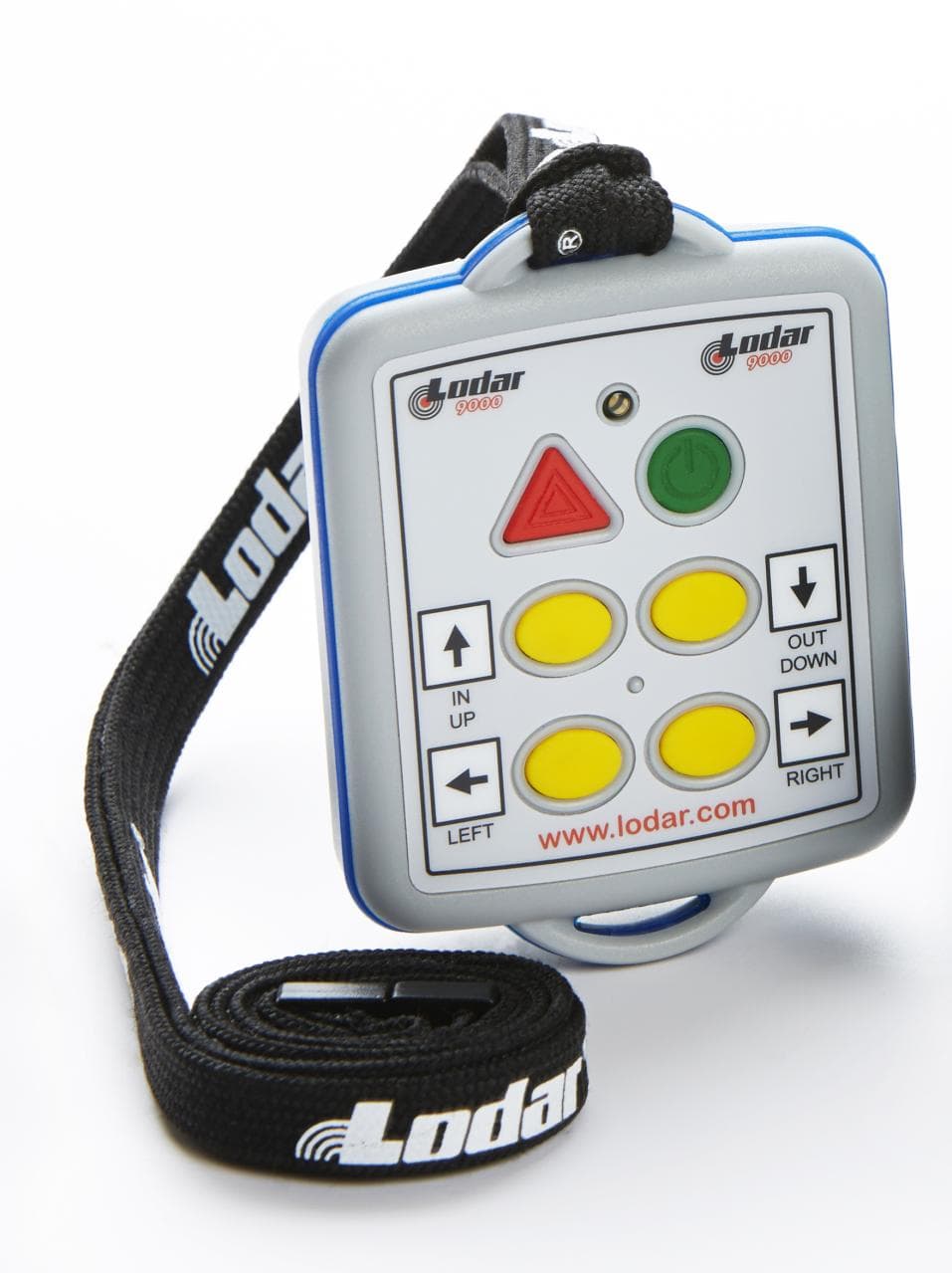
M2H111
Sep 09, 2014111-4
Equipment Class
DSC - Part 15 Security/Remote Control Transmitter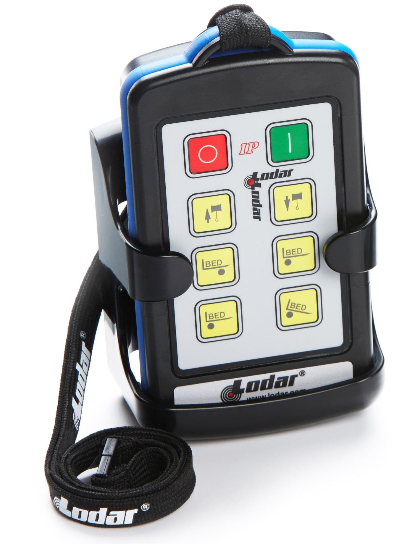
M2H103
Sep 09, 2014103-16
Equipment Class
DSC - Part 15 Security/Remote Control TransmitterM2HLODAR8522
Nov 07, 1996R/C Winch Controller
Equipment Class
DSC - Part 15 Security/Remote Control TransmitterM2HRXLODAR
Nov 07, 1996R/C Winch Controller Receiver
Equipment Class
CYY - Communications Receiver used w/Pt 15 Transmitter