M2KRPC1RPC 2.4 GHz, Voice system.
Innowave ECI Telecom Ltd.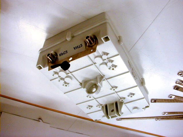
Click to zoom
Application Details
- Equipment Class
- DSS - Part 15 Spread Spectrum Transmitter
- Date of Grant
- Jun 11, 2000
- Application Purpose
- Original Equipment
- Date of Application
- Mar 05, 2000
- Equipment Note
- RPC 2.4 GHz, Voice system.
- Frequency Range
- 2401.00000000 - 2480.00000000
- Company
- Innowave ECI Telecom Ltd.
- Country
- Israel
Documents & Files
Document Text
Text extracted from the exhibit documents filed with the FCC. Open a document above to read the original.
Users Manual
MultiGain Wireless System Manual - Part III Radio Port System Installation and Operation P/N 8638-71410-25 Part III Issue 1.0 August 1999 Company Headquarters InnoWave ECI Wireless Systems Ltd. 4 Hashiloach St. P.O.Box 85 Petach-Tikva 49104 Israel Tel: (972-3) 9263500 Fax: (972-3) 9263636 e-mail: [email protected] www.ecitele.com/innowave ECI Telecom Ltd. 30 Hasivim St. P.O.Box 3083 Petach-Tikva 49130 Israel Tel: (972-3) 9266555 Fax: (972-3) 9266711 www.ecitele.com PROPRIETARY AND CONFIDENTIAL Copyright © 1999 InnoWave ECI Wireless Systems Ltd. All rights reserved The information contained herein is proprietary and confidential and is intended only for the persons to whom it was transmitted by InnoWave ECI Wireless Systems Ltd. Any reproduction, in whole or in part, or the divulgence of any of its contents, without the prior written consent of InnoWave ECI Wireless Systems Ltd., is prohibited. InnoWave ECI Wireless Systems Ltd. shall not be deemed to make any representation or warranty as to the accuracy or completeness of the information contained herein. Information in this product description is subject to change without notice. SAFETY WARNINGS Potentially hazardous voltages exist on the DSL lines, within the RPU and RPC units, and on the line interface card installed in the RPU and RPC. Always observe standard safety precautions during installation, operation, and maintenance of these products. To avoid the possibility of electrical shock, be sure to disconnect the power from the remote power source before you perform any line connections or repairs. Always disconnect all the cables connected to the system before disconnecting the grounding connection. After disconnecting the power from the appropriate RPCU line interface card and disconnecting the cables connected to the line interface card, wait a few seconds for internal capacitors to discharge before removing the card. WARNING The installation procedures described in this Manual must be performed by qualified personnel aware of the hazards involved. The personnel involved in equipment installation must be trained in the installation of MGW systems, and must strictly observe all the safety precautions related to the installation of communication equipment. Never install, remove or adjust antennas, and associated cables, and do not work on masts or towers during a lightning storm. ATTENTION! STATIC SENSITIVE DEVICES PROPER HANDLING AND GROUNDING PRECAUTIONS REQUIRED The MGW system contains components sensitive to electrostatic discharge (ESD). To prevent ESD damage, avoid touching the internal components, and removing cards, touch the frame of an grounded equipment. Keep parts and cards in their antistatic packaging material until you are ready to install. The use of an antistatic wrist strap, connected to the grounded equipment frame or chassis, is recommended when handling cards during installation, removal, or setting of on-board option switches. Do not use a conductive tool, such as a screwdriver or paper clip, to set the position of internal DIP switches. UL INSTALLATION SAFETY INSTRUCTIONS a. Never install telephone wiring during a lightning storm. b. Never install telephone jacks in a wet location unless the jack is specifically designed for wet locations. c. Never touch telephone wires or terminals unless the telephone line has been disconnected at the network interface. Four. Use caution when installing or modifying telephone lines. FEDERAL COMMUNICATIONS COMMISSION (FCC) STATEMENT The RPC and RPU equipment have been tested and found to comply with the limits for a Class B digital device, pursuant to part 15 of the FCC Rules. These limits are designed to provide reasonable protection against harmful interference in a residential installation. This equipment generates, uses and can radiate radio frequency energy and, if not installed and used in accordance with the instructions, may cause harmful interference to radio communications. However, there is no guarantee that interference will not occur in a particular installation. If this equipment does cause harmful interference to radio or television reception, which can be determined by turning the equipment off and on, the user is encouraged to try to correct the interference by one or more of the following measures: -Reorient or relocate the receiving antenna. -Increase the separation between the equipment and receiver. -Connect the equipment into an outlet on a circuit different from that to which the receiver is connected. -Consult the dealer or an experienced radio/TV technician for help. Abbreviations AIU-120 Analog Interface Unit DIU Digital Interface Unit DSL Digital Subscriber Line FAU Fixed Access Unit GOS Grade of Service GSS Global Synchronization System GPS Global Positioning System GTU Global Timing Unit kbps Kilobits per second Mbps Megabits per second MCX MGW Coverage Extender System MCX-L MGW Coverage Extender Local Multiplexer Unit MCX-R MGW Coverage Extender Remote Multiplexer Unit MGW MultiGain Wireless LOS Line of Sight PCM Pulse Code Modulation PRM Port Radio Module RPC Radio Port Coupler Unit RPCU Radio Port Control Unit RPU Radio Port Unit RRU Radio Repeater Unit RS-232C EIA standard for Interface between Data Terminal Equipment and Data Communication Equipment employing serial binary data interchange using an unbalance interface SSFH Spread Spectrum Frequency Hopping TDD Time Division Duplexing TDM Time Division Multiplexing TDMA Time Division Multiple Access WLL Wireless Local Loop Table of Contents Chapter 1 INTRODUCTION 1.1 Scope................................................................................................................................1-1 1.2 Related Publications............................................................................................................1-1 1.3 EQUIPMENT DESCRIPTION................................................................................................1-3 1.3.1 Equipment Versions.......…
Text truncated - open the document above for the full version.
Users Manual
3-1 Chapter 3 RPU INSTALLATION PROCEDURES Section I. GENERAL 3.1 Scope This Chapter provides instructions for the installation of the RPU and of the associated antennas. The information appearing in this Chapter includes: • Unpacking. • Preparation for installation. • Required equipment, tools, and materials. • Mounting options. • Mounting procedures for towers and masts. • Installation and connection procedures, including application of power. 3.2 Unpacking Before unpacking, make a preliminary inspection of the shipping containers, preferably in the presence of a carrier representative. Evidence of damage should be noted and immediately reported to the carrier, and to the nearest InnoWave’s representative. • Carefully open the top side of the packing container and take out the RPU, antennas, and accessories, and place equipment on a clean, flat surface. • Check the received items against the packing slip, and compare with your order. Immediately report any missing items or discrepancies found. • Inspect the equipment carefully for any signs of damage. In case damage is found, contact the manufacturer for repair information, and report the damage to the freight carrier for insurance claims. • Search the container for any additional small items that may be present. • Check that the RPU and antennas comply with the frequency band, in accordance with your order and installation plan. Keep the shipping carton and packaging materials for reuse. Radio Port System Installation and Operation - RPU Installation Procedures 3-2 3.3 Preparation for Installation 3.3.1 Power Considerations The RPU is remotely fed from the RPCU, or from the MCX-R Remote Unit via the DSL lines. The feed voltage is ±80 to ±90 VDC. 3.3.2 Safety Considerations Dangerously high voltages, that may cause injury or death on contact, are present in this equipment and on the lines connected to the RPCU or to the MCX-R unit. In addition, personnel must be aware that under certain external fault conditions, dangerous voltages may appear on the cables connected to the RPU and antennas. WARNING - RF RADIATION Microwave radiation is emitted by the antennas during operation. For your protection and to prevent possible damage to equipment when a fault condition, e.g., lightning strike or contact with high-voltage power lines, occurs on the antennas or on the lines connected to the equipment, the RPU’s the antennas and the lightning rod must be properly earthed at any time. Any interruption of the protective (earthing) connection inside or outside the units or the disconnection of the protective grounding strap, or disconnection or removal of the lightning rod during equipment operation, can make that equipment dangerous. Intentional interruption is prohibited. Before powering this equipment, the grounding strap, must be connected to a protective earth, in accordance with the procedure given in the Grounding and Lightning Protection section (para. 2.3). Radio Port System Installation and Operation - RPU Installation Procedures 3-3 3.4 Required Equipment, Tools and Accessories 3.4.1 RPU and Antenna The RPU and antenna kits contain the following components: • RPU unit. • RPU mounting kit. • Antenna support and antenna mounting kit. • Coaxial cables with lightning protectors. 3.4.2 Installation and Tools Accessories The following tools and accessories are required for the installation of RPU and antennas. • H-shaped antenna support. • Mounting accessories for the antenna support. • Set of metric sockets (must include a 17 mm socket). • Flat blade screwdrivers (one with narrow blade and another with normal blade). • Wire cutter. • Black plastic attachment straps. • Tape and RTV for insulating the RPU and antenna connectors. • Two twisted-pair cables for connection of DSL lines. Use pairs with characteristics suitable for outdoor installation, in accordance with the climatical conditions at the installation site and the applicable local regulations. The pair insulation must have a minimum breakdown voltage of 500V. Use shielded pairs to improve EMI protection. • Grounding straps and/or cables, as required. • Safety belts and other applicable protective equipment for climbing and working on towers and masts. Radio Port System Installation and Operation - RPU Installation Procedures 3-4 Section II. OUTLINE OF INSTALLATION PROCEDURES 3.5 Scope This Section comprises the following information: • Safety warnings. • General requirements (para. Error! Reference source not found.) - contains general mounting considerations, and information concerning site preparation for the installation of RPU stations. • RPU station options (para. 3.7) - contains information concerning the installation options and a description of the equipment and accessories required for each installation option. • Mounting methods (para. 3.8) - contains a description of the supports required for the various mounting options. Never work on roofs, poles, or masts, nor handle telephone lines or outdoor antennas during rain and/or lightning storms. When working on building roofs, poles, or masts, strictly observe the applicable local safety regulations. Use safety belt and other applicable personal protection devices when climbing and working on poles, masts or towers. Dangerously high voltages are present on the lines connected to the RPU. Before connecting the DSL lines, the remote power feed must be deactivated at the RPCU site, in accordance with the installation instructions, and a warning placed on the RPCU to prevent unauthorized application of power. Dangerous voltages may also appear on the lines connected to the RPU as a result of external fault conditions, e.g., accidental contact with high-voltage lines, etc. Take the appropriate precautions to avoid accidents. Radio Port System Installation and Operation - RPU Installation Procedures 3-5 3.6 General Requirements 3.6.1 General RPU stations are usually mounted on poles, masts or towers by means of various supports. To mi…
Text truncated - open the document above for the full version.
Users Manual
4-1 Chapter 4 RPC INSTALLATION PROCEDURES Section I. GENERAL 4.1 Scope This Chapter provides instructions for the installation of the RPC, and of the associated antennas, if used. The information appearing in this Chapter includes: • Unpacking. • Preparation for installation. • Required equipment, tools, and materials. • Mounting options. • Mounting procedures for towers and masts. • Installation and connection procedures, including application of power. 4.2 Unpacking Before unpacking, make a preliminary inspection of the shipping containers, preferably in the presence of a carrier representative. Evidence of damage should be noted and immediately reported to the carrier, and to the nearest InnoWave’s representative. • Carefully open the top side of the packing container and take out the RPC, antennas (when supplied), and accessories, and place equipment on a clean, flat surface. • Check the received items against the packing slip, and compare with your order. Immediately report any missing items or discrepancies found. • Inspect the equipment carefully for any signs of damage. In case damage is found, contact the manufacturer for repair information, and report the damage to the freight carrier for insurance claims. • Search the container for any additional small items that may be present. • Check that the RPC and antennas (if used) comply with the frequency band, in accordance with your order and installation plan. Keep the shipping carton and packaging materials for reuse. Radio Port System Installation and Operation - RPC Installation Procedures 4-2 4.3 Preparation for Installation 4.3.1 Power Considerations The RPC is remotely fed from the RPCU, or from the MCX-R Remote Unit via the DSL lines. The feed voltage is ±80 to ±90 VDC. 4.3.2 Safety Considerations Dangerously high voltages, that may cause injury or death on contact, are present in this equipment and on the lines connected to the RPCU or to the MCX-R unit. In addition, personnel must be aware that under certain external fault conditions, dangerous voltages may appear on the cables connected to the RPC and antennas. WARNING - RF RADIATION Microwave radiation is emitted by the RPC and antennas (if used) during operation. For your protection and to prevent possible damage to equipment when a fault condition, e.g., lightning strike or contact with high-voltage power lines, occurs on the antennas or on the lines connected to the equipment, the RPC’s, the antennas, if used, and the lightning rod must be properly earthed at any time. Any interruption of the protective (earthing) connection inside or outside the units or the disconnection of the protective grounding strap, or disconnection or removal of the lightning rod during equipment operation, can make that equipment dangerous. Intentional interruption is prohibited. Before powering this equipment, the grounding strap, must be connected to a protective earth, in accordance with the procedure given in the Grounding and Lightning Protection section (para. 2.3). Radio Port System Installation and Operation - RPC Installation Procedures 4-3 4.4 Required Equipment, Tools and Accessories 4.4.1 RPC and Antenna The RPC and antenna kits contain the following components: • RPC unit. • RPC mounting kit. • Antenna support and antenna mounting kit (if applicable). • Coaxial cables with lightning protectors. 4.4.2 Installation and Tools Accessories The following tools and accessories are required for the installation of RPC and antennas, if used. • H-support antenna support. • Mounting accessories for the antenna support. • Set of metric sockets (must include a 17 mm socket). • Flat blade screwdrivers (one with narrow blade and another with normal blade). • Wire cutter. • Black plastic attachment straps. • Tape and RTV for insulating the RPC and antenna connectors. • Two twisted-pair cables for connection of DSL lines. Use pairs with characteristics suitable for outdoor installation, in accordance with the climatical conditions at the installation site and the applicable local regulations. The pair insulation must have a minimum breakdown voltage of 500V. Use shielded pairs to improve EMI protection. • Grounding straps and/or cables, as required. • Safety belts and other applicable protective equipment for climbing and working on towers and masts. Radio Port System Installation and Operation - RPC Installation Procedures 4-4 Section II. OUTLINE OF RPC INSTALLATION PROCEDURES 4.5 Scope This Section comprises the following information: • Safety warnings. • General requirements (para. 4.6) - contains general mounting considerations, and information concerning site preparation for the installation of RPC stations. • RPC station options (para. 4.7) - contains information concerning the installation options and a description of the equipment and accessories required for each installation option. • Mounting methods (para. 4.8) - contains a description of the supports required for the various mounting options. Never work on roofs, poles, or masts, nor handle telephone lines or outdoor antennas during rain and/or lightning storms. When working on building roofs, poles, or masts, strictly observe the applicable local safety regulations. Use safety belt and other applicable personal protection devices when climbing and working on poles, masts or towers. Dangerously high voltages are present on the lines connected to the RPC. Before connecting the DSL lines, the remote power feed must be deactivated at the RPCU site, in accordance with the installation instructions, and a warning placed on the RPCU to prevent unauthorized application of power. Dangerous voltages may also appear on the lines connected to the RPC as a result of external fault conditions, e.g., accidental contact with high-voltage lines, etc.. Take the appropriate precautions to avoid accidents. Radio Port System Installation and Operation - RPC Installation Procedures 4-5 4.6 General Requirements 4.6.1 General RPC stations are usually moun…
Text truncated - open the document above for the full version.
Block Diagram
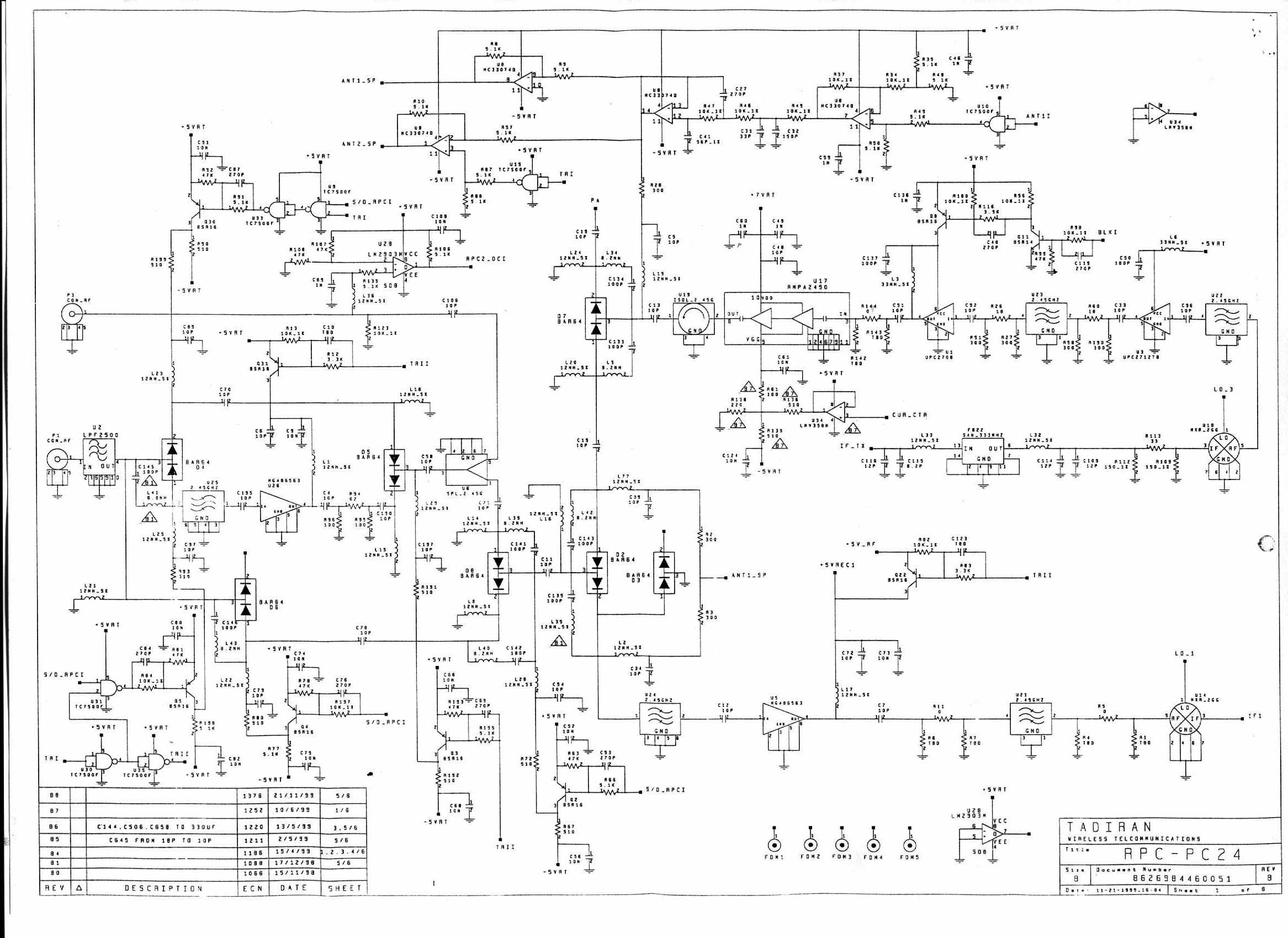
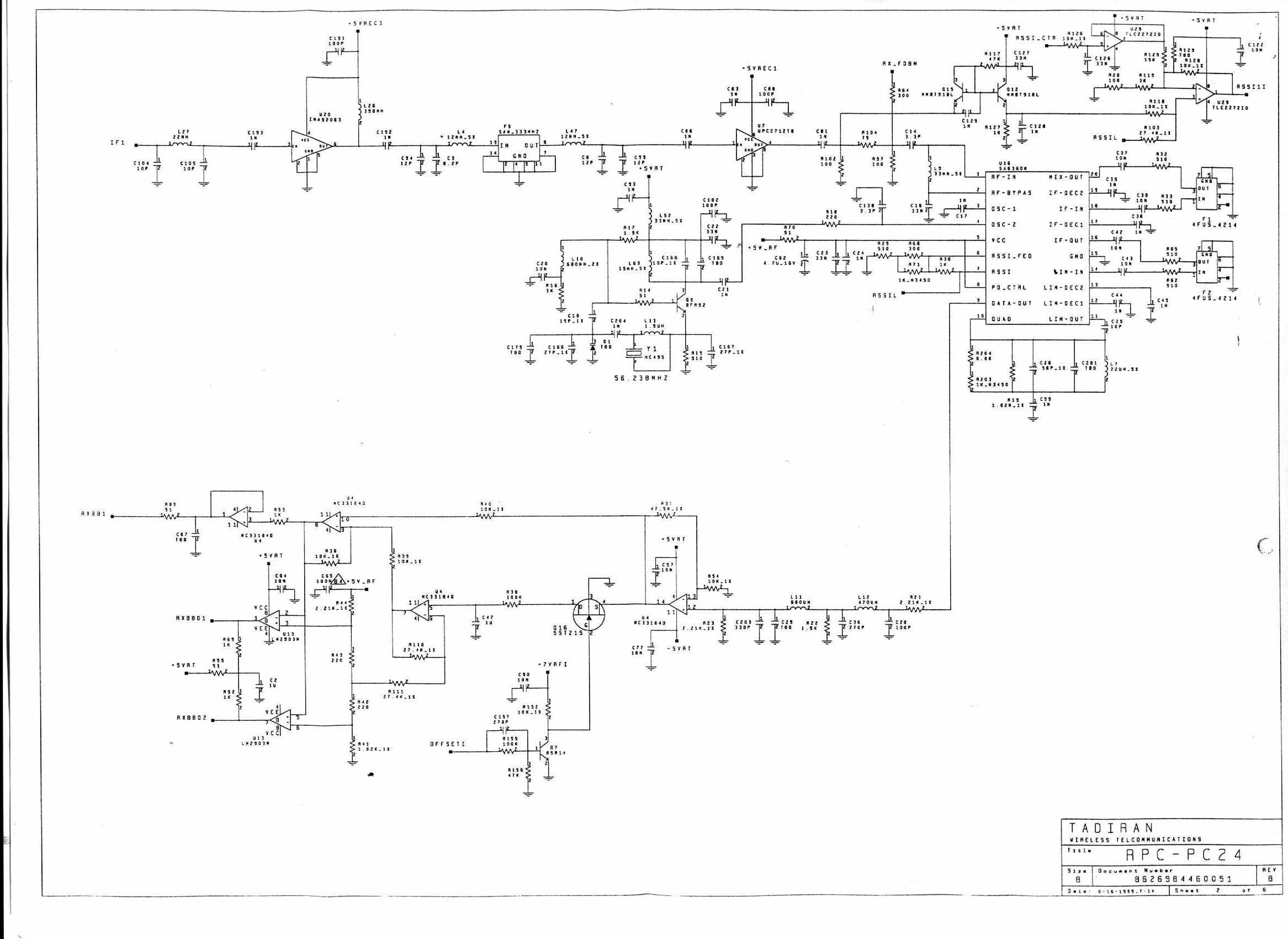
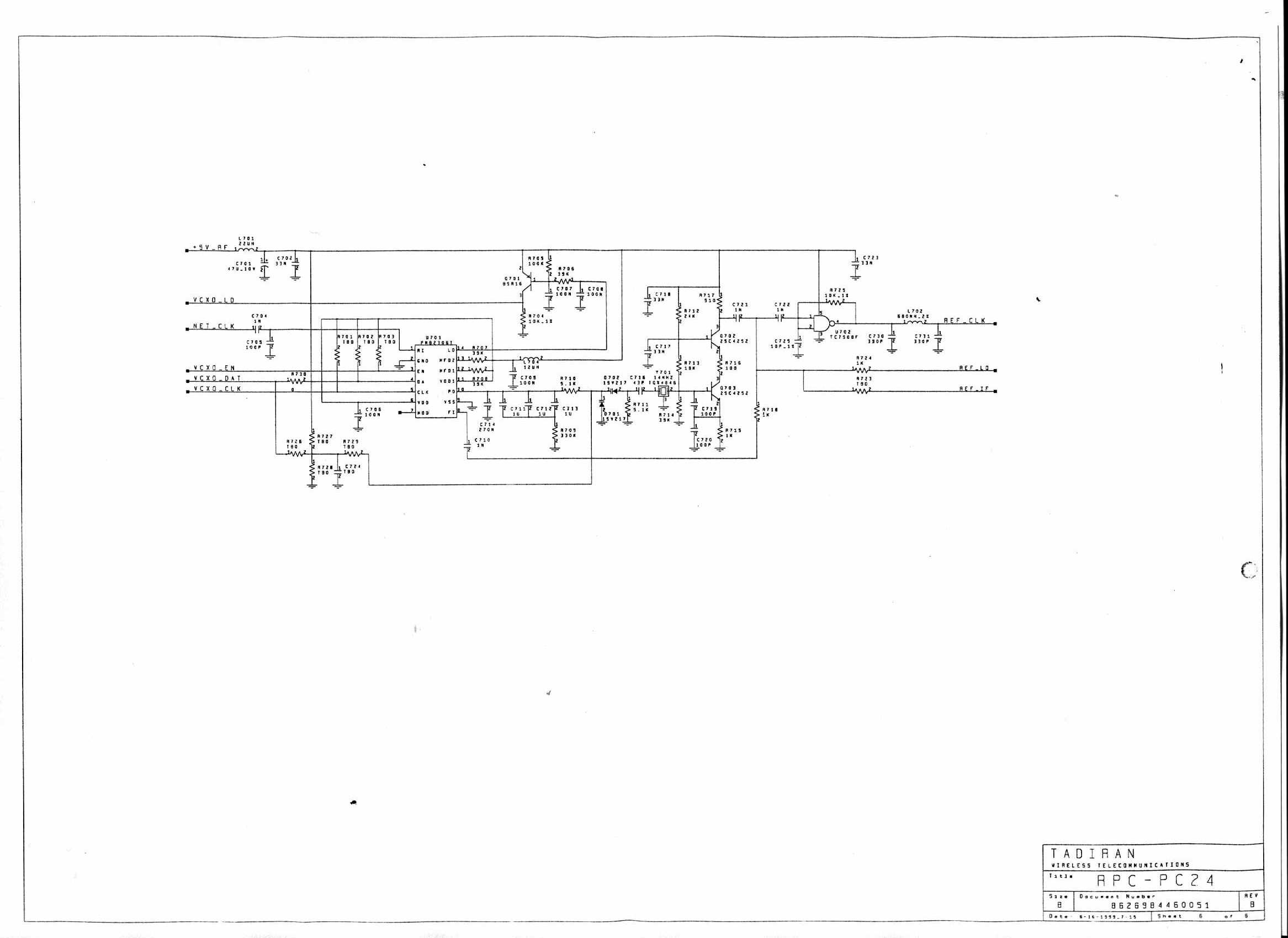
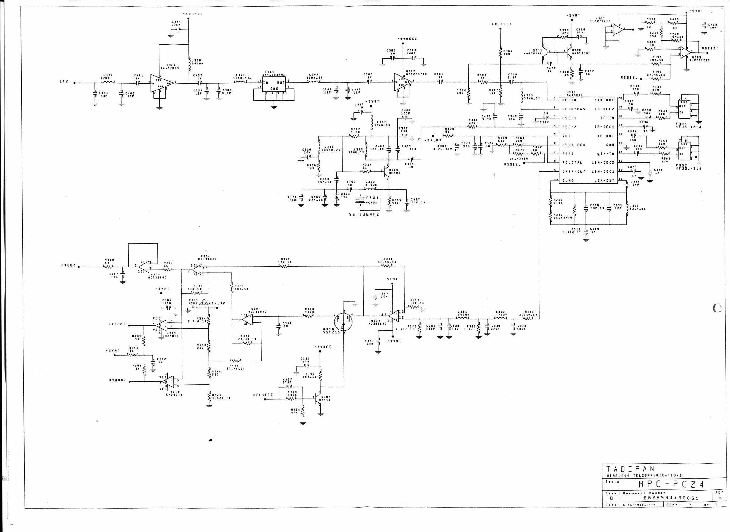
The modules of the RPC contain several frequency generation circuits. The PLI module contains crystal of 15.36MHz. The RF Module (namely the PC module) contains the following crystals: 14MHz, 56.238MHz. The PRC module contains crystal of 24MHz.
Cover Letter(s)
Memorandum 1 ]InnoWave Wireless Systems 4 Hashiloach Street Petach Tikva 49104 Israel Tel: (972-3) 926-3507 Fax: (972-3) 926-3652 www.ecitele.com/innowave March 5, 2000 FEDERAL COMMUNICATIONS COMMISSION EQUIPMENT APPROVAL SERVICES P.O.B. 358315 Pittsburgh, PA 15251-5315 USA Subject: Application for certification of Radio port coupler, model RPC 2.4 GHz, FCC ID: M2KRPC1 Dear Gentlemen, Please find attached our application for certification of Radio port coupler, model RPC 2.4 GHz, FCC ID: M2KRPC1, prepared in accordance with FCC Rules, parts 2 and 15. The product testing and this application for certification were performed by Hermon Laboratories, which is listed by FCC. Hermon Labs responsible person is Dr. Edward Usoskin, tel: 01197266288001, fax:01197266288277, e-mail: [email protected] We hope this application satisfies your requirements. Sincerely yours, Mr. Amnon Beer, Engineering manager
External Photos
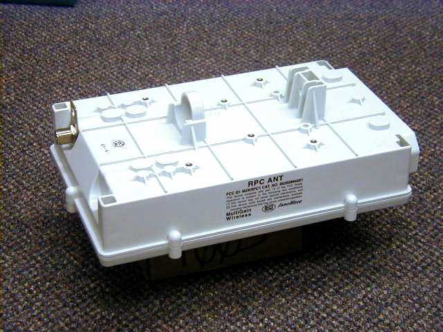
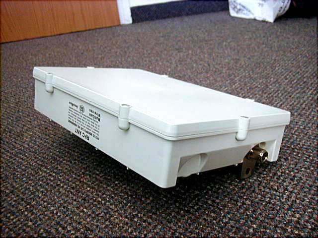
PRC-unit PRC-unit, package PRC-unit, side view PRC-unit, top side PRC-unit comm. side
ID Label/Location Info
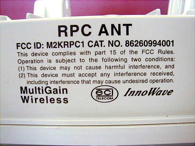
The identification label is imprinted directly to the bottom of the device. The photograph is shown below.
Internal Photos
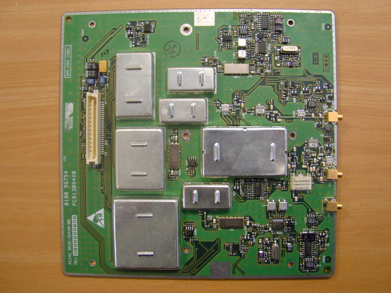
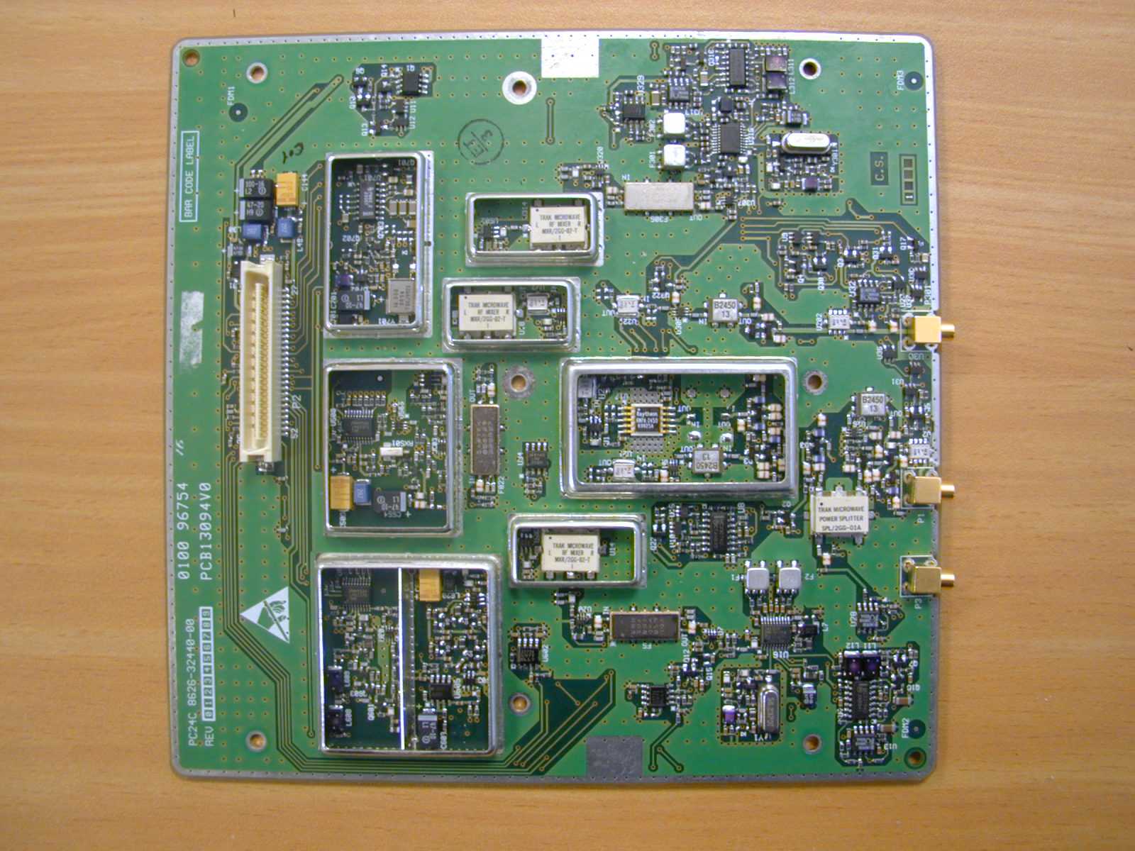
PC-top PC-bottom PC-sub-assembly PLI-top PLI-bottom
Internal Photos
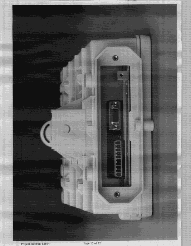
PRC-top PRC-bottom PRC-subassembly PRC-assembly open
Internal Photos
PRC- sub-assembly open PRC-subassembly side view RPC-subassembly bottom view
Operational Description
1-1 1.1 EQUIPMENT DESCRIPTION 1.1.1 Equipment Versions This manual covers the following radio port equipment versions: • Radio Port Unit, RPU, and the associated antennas and mounting accessories. The RPU can be ordered for operation in the following frequency bands: 2.4 GHz and 3.5 GHz. • Radio Port Coupler, RPC, performs the RPU functions with an internal antenna. The RPC can be ordered for operation in the following frequency bands: 2.4 and 3.5 GHz. Figure -1 shows a general view of typical basic RPU and RPC units. Figure -1. Typical RPU and RPC Units, General View 1.1.2 RPC Description 1.1.2.1 RPC Functional Description The RPC is a complete radio port subsystem, which contains the RPU hardware, an internal 60° sectorized antenna and an antenna coupler, that enables connection to another RPC or to an external antenna, for space diversity. Therefore, the RPC simplifies the installation process, reduces the resources and environmental impact relative to typical RPU-based installations, and improves the appearance of the radio base station. The RPC is offered in the following version: • RPC without reflectors for the 2.4 and 3.5 GHz frequency bands. 1.1.2.2 RPC Functional Block Diagram The functional diagram of the RPC is shown in Figure -2. The RPC uses PLI and PRC modules whose functionality is similar to that of the corresponding RPU modules, an internal antenna, and a PC module that includes the transceiver functions of the PRM module used in the RPU, with the addition of a coupler. The coupler is used only in the dual-RPC base station configuration (see para. 1.1.2.5), in which the RPC2 connectors of two RPC units heading in the same direction are cross-connected using two coaxial cables. Space diversity is obtained for each RPC by coupling the internal antenna of the other RPC. The dual RPC configuration supports up to 16 simultaneous calls. RPU RPC Radio Port System Installation and Operation - Introduction 1-2 1.1.2.3 Frequency Oscillators The modules of the RPC contain several frequency generation circuits. The PLI module contains crystal of 15.36MHz. The RF Module (namelt the PC module) contains the following crystals: 14MHz, 56.238MHz. The PRC module contains crystal of 24MHz. 1.1.2.4 Hopping Frequencies sequences list The RPC operates at pseudorandomly hopping frequencies scenario. Upon installation, desired frequencies are loaded to the frequency table in the radio digital memory. Number of frequencies are any combination of more than 75 frequencies in the range of 2400 MHz to 2480MHz. The system assigns a pseudorandomly frequencies order for the radio hops. The order of hops is kept the same all the time after installation. Radio Port System Installation and Operation - Introduction 1-3 Microcontroller Line a nd Radio Interface Switches RF Transmitter RF Receiver 1 RF Receiver 2 PRC PC Line Interface Power Supply Control a nd Data Processor PLI Bearer & Signaling Clock Data RS-232 Control Interface DSL1DSL2 Power ToInternal Circuits RPC Coupler ANT 1 RPC 2 ANT 2 To RPC 2 To RPC 2 Or Antenna Internal Antenna Radio Port System Installation and Operation - Introduction 1-4 Figure -2. RPC Functional Diagram In addition, the RPC can be used with external antennas: • An additional (standard) RPU antenna can be connected to the second connector of the RPC. • For special applications, e.g., for omni-directional coverage or when special antennas are needed, or to support antenna diversity when transmitting on a 3.5 GHz RPC, two external antennas shall be used. In this case, the internal antenna of the RPC can be disconnected in the field and the internal connector can be directly connected to one of the external RF connectors. 1.1.2.5 RPC Configurations This section presents basic configurations using the RPC capabilities. 1.1.2.5.1 Dual-RPC Radio Base Station This configuration, shown in Figure -3, includes two radio base stations, heading in the same direction (Figure -3 shows units without external reflectors: such reflectors are used only with the 1.5 GHz units). The internal antenna of each RPC is used as the second antenna for the other RPC, so that space diversity is obtained for both RPC’s. This configuration, which requires only two units, replaces six units (two RPU’s and four antennas). As a result, it is possible to install four RPC-based radio stations on one H-support. Eventually, installation costs are reduced and environmental and aesthetic impact is minimized. Every installation including multiple radio base stations, heading in the same direction, will include pairs of RPC’s connected according to Figure -3. Figure -3. Dual RPC Configuration 1.1.2.5.2 Single RPC Radio Base Station with Space Diversity A single radio base station with space diversity comprises an RPC and a sectorized antenna. A single cable connects the two units. Both the internal and external antennas are connected via the antenna coupler in the RPC. Radio Port System Installation and Operation - Introduction 1-5 Figure -4 shows a typical RPC radio station. This configuration is used for the installation of a single radio base station, and for the single radio base station left at a location that includes an odd number of radio base stations, heading in the same direction. Sectorized Antenna RPC Figure -4. Single RPC Radio Station 1.1.2.5.3 External Antenna Options The RPC enables the connection of a pair of external antenna pairs (e.g., omni-directional or wider beam-width antennas), whenever needed. To use this option, it is necessary to change internal connections in the RPC. External antennas must always be used on a 3.5 GHz RPC, when it is necessary to use antenna diversity in the transmit mode. Radio Port System Installation and Operation - Introduction 1-6 1.2 Technical Characteristics DSL Line Interface (RPCU Interface) Number of DSL Interfaces two Line Interface Type Based on ANSI T1.600 Basic Line Bit Rate 144 kbps per DSL line Line Code 2B1Q Transmit Signal Level 5V peak Line Nominal I…
Text truncated - open the document above for the full version.
Operational Description
Antenna description The RPC is a complete radio port subsystem, which contains the RPU (Radio port unit) hardware, an internal 60° sectorized antenna and an antenna coupler, that enables connection to another RPC or to an external antenna, for space diversity. The coupler is used only in the dual-RPC base station configuration, in which the RPC2 connectors of two RPC units heading in the same direction are cross- connected using two coaxial cables. Space diversity is obtained for each RPC by coupling the internal antenna of the other RPC. The dual RPC configuration supports up to 16 simultaneous calls. In the single RPC base station, and also when using special external antennas configurations, the coupler is bypassed. Microcontroller Line a nd Radio Interface Switches RF Transmitter RF Receiver 1 RF Receiver 2 PRC PC Line Interface Power Supply Control a nd Data Processor PLI Bearer & Signaling Clock Data RS-232 Control Interface DSL1DSL2 Power ToInternal Circuits RPC Coupler ANT 1RPC 2ANT 2 To RPC 2To RPC 2 Or Antenna Internal Antenna In addition, the RPC can be used with external antennas: • An additional (standard) RPU antenna can be connected to the second connector of the RPC. • For special applications, e.g., for omni-directional coverage or when special antennas are needed, or to support antenna diversity when transmitting on a 3.5 GHz RPC, two external antennas shall be used. In this case, the internal antenna of the RPC can be disconnected in the field and the internal connector can be directly connected to one of the external RF connectors. Single RPC Radio Base Station with Space Diversity A single radio base station with space diversity comprises an RPC and a sectorized antenna. A single cable connects the two units. Both the internal and external antennas are connected via the antenna coupler in the RPC. Figure 0-1 shows a typical RPC radio station. This configuration is used for the installation of a single radio base station, and for the single radio base station left at a location that includes an odd number of radio base stations, heading in the same direction. Sectorized Antenna RPC Figure 0-1. Single RPC Radio Station External Antenna Options The RPC enables the connection of a pair of external antenna pairs (e.g., omni- directional or wider beam-width antennas), whenever needed. To use this option, it is necessary to change internal connections in the RPC. External antennas must always be used on a 3.5 GHz RPC, when it is necessary to use antenna diversity in the transmit mode. Additional information about antennas, their installation and maintenance can be found in User manual.
Operational Description
Hopping sequences list The RPC operates at pseudorandomly hopping frequencies scenario. Upon installation, desired frequencies are loaded to the frequency table in the radio digital memory. Number of frequencies are any combination of more than 75 frequencies in the range of 2400 MHz to 2480MHz. The system assigns a pseudorandomly frequencies order for the radio hops. The order of hops is kept the same all the time after installation.
Operational Description
Memorandum 1 To: Hermon Labs. InnoWave Wireless Systems 4 Hashiloach Street Petach Tikva 49104 Israel From: Amnon Beer Tel: (972-3) 926-3507 Fax: (972-3) 926-3652 Subject: RPC Associated Receiver Compliance Information. The Radio Port & Coupler (RPC) unit is working in TDMA mode. Both receive and transmit frequencies of the radio are set to the same frequency at each hopping frequency for 2mSec. At the first 1mSec, the RPC’s receiver is activated, and data from the subscriber radio is received by the RPC, after one millisecond, the receiver is deactivated. After deactivation of the receiver, the radio remains at the same frequency, and the transmitter is activated. The transmitter transmits data to the subscriber radio for another 1 millisecond. After completion of 1millisecond receive period, and 1 millisecond of transmit period, the radio software controls the RPC to change frequency to the next hopping frequency. After the RPC has been settled to the new frequency another receive and transmit cycles start for 2 millisecond as described. According to this procedure, the receiver and the transmitter of the RPC, share the same frequencies all the time. Sincerely Amnon Beer
Operational Description
InnoWave Wireless Systems 4 Hashiloach Street Petach Tikva 49104 Israel PAGE 1 OF 2 DATE: 17 May., 2000 TO: FCC FROM: Amnon Beer Subject: Coordination Between Transmitters 1) Our equipment complies with…
Text truncated - open the document above for the full version.
Contact Information
Applicant
Amnon Beer(Engineering Manager)
Technical Contact
Hermon LaboratoriesEdward Usoskin
[email protected]+972 66288001
HaRakevet Industrial Zone · Binyamina · Israel
Non-Technical Contact
Innowave ECI Telecom Ltd.Amnon Beer
[email protected]972 39263507
Test Firm
Hermon Laboratories Ltd.Alexander Usoskin
Technical Specifications
| # | Rule Parts | Frequency Range | Power Output |
|---|---|---|---|
| 1 | 15C | 2.40 GHz - 2.48 GHz | 150.00 mW |
Other Applications from Innowave ECI Telecom Ltd.
M2KFAU4
Sep 24, 1998WLL System Fixed Access Transmitter
Equipment Class
DSS - Part 15 Spread Spectrum TransmitterM2KRPU1
May 28, 1998Wireless Local Loop System Basestation Maximum output power: 275mW
Equipment Class
DSS - Part 15 Spread Spectrum Transmitter