M4B6180010Wireless LAN Card
Toyota Industries Corporation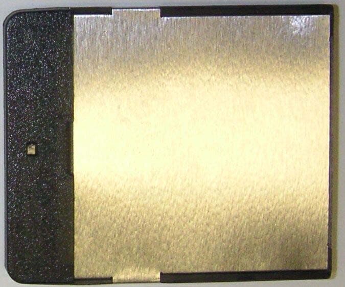
Click to zoom
Application Details
- Equipment Class
- DTS - Digital Transmission System
- Date of Grant
- Jul 10, 2003
- Application Purpose
- Original Equipment
- Date of Application
- Jul 10, 2003
- Equipment Note
- Wireless LAN Card
- Frequency Range
- 2412.00000000 - 2462.00000000
- Country
- Japan
Documents & Files
Document Text
Text extracted from the exhibit documents filed with the FCC. Open a document above to read the original.
Users Manual
Wireless LAN module Wireless LAN module GIGAWAVE GIGAWAVE CF CF - - CARD CARD 6180010 6180010 Operation manual Operation manual Thank you for your choosing our product “GIGAWAVE [6180010]. GIGAWAVE [6180010] is a wireless LAN client adapter which conforms to IEEE802.11b and supports CF Card TYPE I Extended. This document is a quick reference guide for our product. Features Features High data rates up to 11 Mbps IEEE 802.11b compliant technology Small dimensions (CF Card TYPE I Extended) Supports a de facto standard host interface (CF and Compact Flash Specification Revision 1.4) Low power consumption Security features include 64-bit and 128-bit WEP (Wired Equivalent Privacy) Wi-Fi certified product Introduction Operating Operating Steps Steps STEP1STEP2 Equipment Equipment Product and CD-ROM System requirement Installation Installation Driver STEP3 Configuration Configuration Wireless LAN Package Contents Package Contents GIGAWAVE [6180010] device CD-ROM including drivers and utility softwares. System requirement Hardware with the CF Card Slot (TYPE I) compliant with CF card standard or the PC card Slot*. Hardware with the CD-ROM drive *: If our product is inserted into a PC card slot, it needs an adapter which converts a CF card into a PC card. Hardware requirement Compatible PC/AT Operating System Windows98 Second Edition Windows2000 Windows XP Compatibility with another devices IEEE 802.11b compliant Wireless LAN products (Wi-Fi certified product is recommended) In case of connecting to a wired LAN, the wireless LAN access point is required. For Windows98 Second Edition For Windows98 Second Edition Insert the [6180010] into the CF Card slot on your computer, then “Add New Hardware Wizard” will appear, informing you that it has found the wireless LAN card. Click on “Next”. Choose “Search for an appropriate driver to your device in use now” and click on “Next” Insert the “Driver and Utility disk” into the CD-ROM drive. Choose “Specify Location,” and type the drive name of CD-ROM. And click on “Next”. A message informing you that it has found “GIGAWAVE Wireless LAN CF Card” should appear. And click on “Next” After the driver is installed on your computer, click on “Finish”. When you are asked if you want to restart your computer. Click on “Yes” and it will restart. Installation of the driver is completed. STEP2Installation STEP2Installation For Windows2000 For Windows2000 Insert the [6180010] adapter into the CF Card slot on your computer, then “Add New Hardware Wizard” will appear, informing you that it has found the Wireless LAN Card. Click on “Next”. Verify that “GIGAWAVE Wireless LAN CF Card” is found, then select “Search for a optimal driver for my device” and click on “Next”. The locate Driver Files dialog appears. Select “Specify a location”, and click “Next”. Insert the “Driver and Utility disk” into CD-ROM drive. On the “Driver from disk provided by hardware manufacture”, select CD-ROM and Click on “OK”. When the message ”The driver for this device is founded” appears, click on “Next”. Check that it has found “GIGAWAVE Wireless LAN CF Card”. And click on “Yes” After the driver is installed on your computer, click on “Finish”. Installation of the driver is completed. For Windows XP For Windows XP Insert the [6180010] adapter into the CF Card slot on your computer, then “Add New Hardware Wizard” will appear, informing you that it has found the Wireless LAN Card. Insert the “Driver and Utility disk” into CD-ROM drive. Verify that “GIGAWAVE Wireless LAN CF Card” is found, then select “Install the Software Automatically” and click on “Next”. After the driver is installed on your computer, click on “Finish”. Installation of the driver is completed. STEP2Installation How to How to configurate configurate wireless LAN setting. wireless LAN setting. When the installation of the driver is completed, an icon will appear in the task bar. Then , double click the icon. Status dialog of GWCF Wireless Setting will appear and select the Configuration Tab. Input SSID assigned to other communicators in the Network name field. Select communication mode in the Network type field. PeertoPeerThis mode is mainly used to transmit files between several PCs. As communication is achieved between several PCs, an access point is not required. Access PointThis mode is mainly used to connect to a wired network, such as connecting to Internet. As this connects to a wired network, an access point is required. In Peer-to-Peer mode, the user can select a channel when it connects. A user can select the transmission rate in the Transmit Rate field. If settings 3 to 6 are changed, click on “Apply” and enable new settings. Others Others In order to use WEP, click on the Encryption Tab in the GWCF Wireless Settings. The user can select the encryption mode from Disable, 64-bit and 128-bit. The Encryption Key should be inputted with a hexadecimal number. (10 letters with 64-bit WEP and 26 letters with 128-bit WEP) Use the key assigned to other communicators. STEP3Configuration Troubleshooting NOTICE This equipment has been tested and found to comply with the limits for a Class B digital device, pursuant to part 15 of the FCC Rules. These limits are designed to provide reasonable protection against harmful interference in a residential installation. This equipment generates, uses and can radiate radio frequency energy and, if not installed and used in accordance with the instructions, may cause harmful interference to radio communications. However, there is no guarantee that interference will not occur in a particular installation. If this equipment does cause harmful interference to radio or television reception,which can be determined by turning the equipment off and on, the user is encouraged to try to correct the interference by one or more of the following measures: -Reorient or relocate the receiving antenna -Increase the separation between the equipment and receiver. -Connect the equipment into an outlet on a circu…
Text truncated - open the document above for the full version.
Cover Letter(s)
Electrical & Electronic Engineering Dept. Corporate Technical Center 1-29-6, Hamamatsu-cho, Minato-ku Tokyo 105-0013 Japan TEL : +81-3-5733-5316 URL : www.toyota-industries.com Request for Confidentiality Date: June 27, 2003 American Telecommunications Certification Body, Inc. 6731 Whittier Avenue Suite C110 McLean, VA 22101 RE: Certification Application FCC ID: M4B6180010 Please be advised that the following information is to be held confidential and behalf of, TOYOTA INDUSTRIES CORPORATION: Block Diagram Schematics Theory of Operation The application contains technical information which TOYOTA INDUSTRIES CORPORATION, deems to be trade secrets and proprietary. If made public, the information might be used to the disadvantage of the applicant in the market place. Thank you for your attention to this matter. Hiroshi Miyake Assistant General Manager Project Leader Electrical & Electronic Engineering Dept. Corporate Technical Center
Cover Letter(s)
Electrical & Electronic Engineering Dept. Corporate Technical Center 1-29-6, Hamamatsu-cho, Minato-ku Tokyo 105-0013 Japan TEL : +81-3-5733-5316 URL : www.toyota-industries.com Letter Of Agency Date: June 27, 2003 American Telecommunications Certification Body, Inc. 6731 Whittier Avenue Suite C110 McLean, VA 22101 To Whom It May Concern: Please be advised that TOYOTA INDUSTRIES CORPORATION, authorizes UL Apex Co., Ltd. to act on our behalf, until otherwise notified, for applications submitted to American Telecommunications Certification Body, Inc. (ATCB). We certify that we are not subject to denial of federal benefits, that includes FCC benefits, pursuant to Section 5301 of the Anti-Drug Abuse ACT of 1988, U.S.C. 862. Further, no party, as defined in 47 CFR 1.2002(b), to the application is subject to denial of federal benefits, that includes FCC benefits. Thank you for your attention to this matter. Sincerely Hiroshi Miyake Assistant General Manager Project Leader Electrical & Electronic Engineering Dept. Corporate Technical Center
Cover Letter(s)
American Telecommunications Certification Body Inc. 6731 Whittier Ave, McLean, VA 22101 July 3, 2003 RE: FCC ID: M4B6180010 Attention: Yoshiko Mizuta I have a few comments on this Application. 1. Please note that neither the label nor the manual contain the 2-condition statement required by Part 15. Please provide a label showing the 2 condition statement as required by 15.19. 2. Please note that the device photos show an rf connector for use with an external antenna. The schematics show this as well. Is this connector a test port or is this connector for the intent of connecting to an external antenna for normal use? The block diagram explanation does not provide information on this connector. Please explain. 3. FYI – no action needed. Please note that the proper equipment code for this type device is DTS not DSS. 4. Please provide the required power drift information on all Device SAR measurement plots. Dennis Ward mailto:[email protected] The items indicated above must be submitted before processing can continue on the above referenced application. Failure to provide the requested information may result in application termination. Correspondence should be considered part of the permanent submission and may be viewed from the Internet after a Grant of Equipment Authorization is issued. Please do not respond to this correspondence using the email reply button. In order for your response to be processed expeditiously, you must submit your documents through the AmericanTCB.com website. Also, please note that partial responses increase processing time and should not be submitted. Any questions about the content of this correspondence should be directed to the sender.
Cover Letter(s)
7 July, 2003 Subject : FCC ID: M4B6180010 Dear Mr. Dennis Ward, Regarding to your comments for FCC ID: M4B6180010 on July 3, 2003, please find the following replies; 1. We submit the revised manual. (Please see uploaded file.) 2. The rf port in the device photo is not for use with an external antenna. It has specific figure and this port is only for the testing. 3. We understand. Thank you. 4. Please refer to this following indication from “OET 65 Supplement C EAB Part 22/24 SAR Review Reminder Sheet 01/2002” issued by FCC; 1) Output Power d) Maximum output power (conducted) or SAR drift measured at same position in liquid before and after each SAR test? We measure Conducted Power not SAR drift. The result of measurement is indicated in 13.1 of Section 13 in our Test report (23KE0006-HO). (Please see uploaded file.) Sincerely yours, Kanako Sanda (Ms.) UL Apex Co., Ltd.
External Photos
FCC ID : M4B6180010 External Photos To y o t a I n d u s t r i e s C o r p o r a t i o n Front Back FCC ID : M4B6180010 External Photos To y o t a I n d u s t r i e s C o r p o r a t i o n W-LAN Card with cover No.1 W-LAN Card with cover No.2
Internal Photos
FCC ID : M4B6180010 Internal Photo Toyota Industries Corporation Circuit Board with shield case (front side) Circuit Board without shield case (front side) FCC ID : M4B6180010 Internal Photo Toyota Industries Corporation Circuit Board (back side)
RF Exposure Info
Test report No. : 23KE0006-HO Page : 2 of 56 Issued date : June 20,2003 FCC ID : M4B6180010 UL Apex Co., Ltd. Head Office EMC Lab. 4383-326 Asama-cho, Ise-shi, Mie-ken 516-0021 JAPAN Telephone: +81 596 24 8116 Facsimile: +81 596 24 8124 CONTENTS PAGE SECTION 1 : Client information 3 SECTION 2 : Equipment under test (E.U.T.) 3 SECTION 3 : Requirements for compliance testing defined by the FCC 4 SECTION 4 : Dosimetric assessment setup 4 SECTION 5 : Test system specifications 7 SECTION 6 : Measurement outline 8 SECTION 7 : Test setup of EUT 9 SECTION 8 : Measurement uncertainty 10 SECTION 9 : Simulated tissue liquid parameter 11 SECTION 10 : System validation data 12 SECTION 11 : Evaluation procedure 13 SECTION 12 : Exposure limit 14 SECTION 13 : SAR Measurement results 15 SECTION 14 : Equipment & calibration information 16 SECTION 15 : References 17 SECTION 16 : APPENDIX 17 APPENDIX 1 : Photographs of test setup APPENDIX 2 : SAR Measurement data APPENDIX 3 : Validation Measurement data APPENDIX 4 : System Validation Dipole (D2450V2,S/N: 713) APPENDIX 5 : Dosimetric E-Field Probe Calibration(ET3DV6,S/N: 1684) Test report No. : 23KE0006-HO Page : 3 of 56 Issued date : June 20,2003 FCC ID : M4B6180010 UL Apex Co., Ltd. Head Office EMC Lab. 4383-326 Asama-cho, Ise-shi, Mie-ken 516-0021 JAPAN Telephone: +81 596 24 8116 Facsimile: +81 596 24 8124 SECTION 1 : Client information Company Name : TOYOTA INDUSTRIES CORPORATION Brand Name : - Address : Hamamatsusho-CenterBuil-6F 1-29-6, Hamamatsu-cho, Minato-ku Tokyo 105-0013 Japan Telephone Number : +81-03-5733-5317 Facsimile Number : +81-03-5401-0575 Contact Person : Hideki Fujii SECTION 2 : Equipment under test (E.U.T.) 2.1 Identification of EUT APPLICANT : TOYOTA INDUSTRIES CORPORATION Type of Equipment : Wireless LAN Card Model No. : GIGAWAVE 6180010 Serial No. : 000016 Rating : DC3.0V +/- 0.3V Country of Manufacture : Japan Receipt Date of Sample : June 01,2003 Condition of EUT : Production prototype Tx Frequency : 2412~2462MHz Modulation : DSSS [DBPSK,DQPSK,CCK] Max.Output Power Tested : 15.2dBm Peak Conducted Antenna Type : Chip Dielectric Antenna Battery option : Only one model with EUT Category Identified : Portable device Test report No. : 23KE0006-HO Page : 4 of 56 Issued date : June 20,2003 FCC ID : M4B6180010 UL Apex Co., Ltd. Head Office EMC Lab. 4383-326 Asama-cho, Ise-shi, Mie-ken 516-0021 JAPAN Telephone: +81 596 24 8116 Facsimile: +81 596 24 8124 SECTION 3 : Requirements for compliance testing defined by the FCC The US Federal Communications Commission has released the report and order “Guidelines for Evaluating the Environmental Effects of RF Radiation", ET Docket No. 93-62 in August 1996. The order requires routine SAR evaluation prior to equipment authorization of portable transmitter devices, including portable telephones. For consumer products, the applicable limit is 1.6 mW/g for an uncontrolled environment and 8.0 mW/g for an occupational/controlled environment as recommended by the ANSI/IEEE standard C95.1-1992. According to the Supplement C of OET Bulletin 65 “Evaluating Compliance with FCC Guide-lines for Human Exposure to Radio frequency Electromagnetic Fields", released on Jun 29, 2001 by the FCC, the device should be evaluated at maximum output power (radiated from the antenna) under “worst-case” conditions for normal or intended use, incorporating normal antenna operating positions, device peak performance frequencies and positions for maximum RF energy coupling. 1 Specific Absorption Rate (SAR) is a measure of the rate of energy absorption due to exposure to an RF transmitting source (wireless portable device). 2 IEEE/ANSI Std. C95.1-1992 limits are used to determine compliance with FCC ET Docket 93-62. SECTION 4 : Dosimetry assessment setup These measurements were performed with the automated near-field scanning system DASY3 from Schmid & Partner Engineering AG (SPEAG). The system is based on a high precision robot (working range greater than 0.9 m), which positions the probes with a positional repeatability of better than +/- 0.02 mm. Special E- and H-field probes have been developed for measurements close to material discontinuity, the sensors of which are directly loaded with a Schottky diode and connected via highly resistive lines to the data acquisition unit. The SAR measurements were conducted with the dosimetry probe ET3DV6, SN: 1684 (manufactured by SPEAG), designed in the classical triangular configuration and optimized for dosimetric evaluation. The probe has been calibrated according to the procedure described in [2] with accuracy of better than +/-10%. The spherical isotropy was evaluated with the procedure described in [3] and found to be better than +/-0.25 dB. The phantom used was the SAM Twin Phantom as described in FCC supplement C, IEE P1528 and CENELEC EN50361. Test report No. : 23KE0006-HO Page : 5 of 56 Issued date : June 20,2003 FCC ID : M4B6180010 UL Apex Co., Ltd. Head Office EMC Lab. 4383-326 Asama-cho, Ise-shi, Mie-ken 516-0021 JAPAN Telephone: +81 596 24 8116 Facsimile: +81 596 24 8124 4.1 Configuration and peripherals The DASY3 system for performing compliance tests consist of the following items: 1. A standard high precision 6-axis robot (Stäubli RX family) with controller and software. 2. An arm extension for accommodating the data acquisition electronics (DAE). 3. A dosimetric probe, i.e., an isotropic E-field probe optimized and calibrated for usage in tissue simulating liquid. The probe is equipped with an optical surface detector system. 4. A data acquisition electronic (DAE), which performs the signal amplification, signal multiplexing, AD-conversion, offset measurements, mechanical surface detection, collision detection, etc. The unit is battery powered with standard or rechargeable batteries. The signal is optically transmitted to the EOC. 5. A unit to operate the optical surface detector, which is connected to the EOC. 6. The Electro-optical coupler (EOC) performs the conversion …
Text truncated - open the document above for the full version.
RF Exposure Info
Test report No. : 23KE0006-HO Page : 21 of 56 Issued date : June 20,2003 FCC ID : M4B6180010 UL Apex Co., Ltd. Head Office EMC Lab. 4383-326 Asama-cho, Ise-shi, Mie-ken 516-0021 JAPAN Telephone: +81 596 24 8116 Facsimile: +81 596 24 8124 APPENDIX 2 : SAR Measurement data Test report No. : 23KE0006-HO Page : 31 of 56 Issued date : June 20,2003 FCC ID : M4B6180010 UL Apex Co., Ltd. Head Office EMC Lab. 4383-326 Asama-cho, Ise-shi, Mie-ken 516-0021 JAPAN Telephone: +81 596 24 8116 Facsimile: +81 596 24 8124 APPENDIX 3 : Validation Measurement data
RF Exposure Info
Test report No. : 23KE0006-HO Page : 33 of 56 Issued date : June 20,2003 FCC ID : M4B6180010 UL Apex Co., Ltd. Head Office EMC Lab. 4383-326 Asama-cho, Ise-shi, Mie-ken 516-0021 JAPAN Telephone: +81 596 24 8116 Facsimile: +81 596 24 8124 APPENDIX 4 : System Validation Dipole (D2450V2,S/N: 713)
RF Exposure Info
Test report No. : 23KE0006-HO Page : 43 of 56 Issued date : June 20,2003 FCC ID : M4B6180010 UL Apex Co., Ltd. Head Office EMC Lab. 4383-326 Asama-cho, Ise-shi, Mie-ken 516-0021 JAPAN Telephone: +81 596 24 8116 Facsimile: +81 596 24 8124 APPENDIX 5 : Dosimetric E-Field Probe Calibration (ET3DV6,S/N: 1684)
Test Report
Test report No. : 23JE0006-YK-1 Page : 2 of 42 Issued date : June 16, 2003 FCC ID : M4B6180010 UL Apex Co., Ltd. YAMAKITA EMC LAB. 907 Kawanishi, Yamakita-machi, Ashigarakami-gun, Kanagawa-ken, 258-0124 JAPAN Telephone: +81 465 77 1011 Facsimile: +81 465 77 2112 MF060b(10.04.03) Table of Contents Page 1 GENERAL INFORMATION 3 1.1 Tested Methodology 3 1.2 Test Facility 3 2 PRODUCT DESCRIPTION 4 3 SYSTEM TEST CONFIGURATION 5 3.1 Justification 5 3.2 Configuration of Tested System 6 4 MEASUREMENT UNCERTAINTY 7 5 SUMMARY OF TEST 8 5.1 §15.207 Conducted Emissions 8 5.2 §15.247(a)(2) 6dB Bandwidth (Antenna Port Conducted) 8 5.3 §15.247(b)(3) Maximum Peak Out Put Power (Antenna port Conducted) 8 5.4 §15.247(c) Out of Band Emissions (Radiated) 9 5.5 §15.247(c) Out of Band Emissions (Antenna Port Conducted) 9 5.6 §15.247(d) Power Density (Antenna Port Conducted) 9 Contents of Appendixes 10 APPENDIX 1: Photographs of test setup 11 APPENDIX 2: Test Data 14 APPENDIX 3: Test instruments 42 Test report No. : 23JE0006-YK-1 Page : 3 of 42 Issued date : June 16, 2003 FCC ID : M4B6180010 UL Apex Co., Ltd. YAMAKITA EMC LAB. 907 Kawanishi, Yamakita-machi, Ashigarakami-gun, Kanagawa-ken, 258-0124 JAPAN Telephone: +81 465 77 1011 Facsimile: +81 465 77 2112 MF060b(10.04.03) 1 GENERAL INFORMATION Company Name : Toyota Industries Corporation Brand Name : - Address : Hamamatsucho-Centralbuil-6F, 1-29-6, Hamamatsu-cho, Minato-ku, Tokyo, 105-0013 JAPAN Telephone Number : +81 3 5733 5317 Facsimile Number : +81 3 5401 0575 Contact Person : Hideki Fujii Type of Equipment : Wireless LAN Card Model No. : GIGAWAVE 6180010 Serial No. : 000016 Rating : DC3.3V Country of Manufacture : Japan Receipt Date of Sample : May 19, 2003 Condition of E.U.T. : Production prototype Regulation(s) : FCC Part15 Subpart C, Section 15.247 Test Site : UL Apex Yamakita EMC Lab. No.1 Open Test Site and No.4 Shielded Room 1.1 Tested Methodology The measurements were performed according to the procedures in ANSI C63.4 (2001). These tests were also referred to FCC 97-114 “Guidance on Measurement for Direct Sequence Spread Spectrum Systems”. 1.2 Test Facility This site has been fully described in a report submitted to FCC office, and accepted on September 20, 2002. (No.1 Open Test Site Registration No.: 95486) NVLAP Lab. code : 200441-0 Test report No. : 23JE0006-YK-1 Page : 4 of 42 Issued date : June 16, 2003 FCC ID : M4B6180010 UL Apex Co., Ltd. YAMAKITA EMC LAB. 907 Kawanishi, Yamakita-machi, Ashigarakami-gun, Kanagawa-ken, 258-0124 JAPAN Telephone: +81 465 77 1011 Facsimile: +81 465 77 2112 MF060b(10.04.03) 2 PRODUCT DESCRIPTION Model: GIGAWAVE 6180010, (referred to as the EUT in this report), is a Wireless LAN Card. Clock frequency used in EUT : 44MHz Frequency Characteristics : 2412 - 2462MHz Channel Characteristics : 11 channel selectable by 16MHz and 5MHz spacing Modulation : DSSS [DBPSK (1M), DQPSK (2M), CCK (5.5M-11M)] Antenna Type : Chip dielectric antenna Antenna Gain : MAX 2dBi ITU Emission Code(s) : G1D Power Supply : DC 3.3V Operation Temperature range : -20 - 60 deg. C. Antenna Connector Type : none *FccPart15.31(e) The host device PC7NW5-URQ4C9110 provides the Wireless LAN Card with stable power supply (DC3.3V), and the power is not changed when voltage of the personal computer is varied. Therefore, the Wireless LAN Card complies power supply regulation. *FccPart15.203 The Wireless LAN Card and its antenna comply with this requirement since this antenna is built in Wireless LAN Card when they are put up for sale and they are used with a particular antenna connector. Test report No. : 23JE0006-YK-1 Page : 5 of 42 Issued date : June 16, 2003 FCC ID : M4B6180010 UL Apex Co., Ltd. YAMAKITA EMC LAB. 907 Kawanishi, Yamakita-machi, Ashigarakami-gun, Kanagawa-ken, 258-0124 JAPAN Telephone: +81 465 77 1011 Facsimile: +81 465 77 2112 MF060b(10.04.03) 3 SYSTEM TEST CONFIGURATION 3.1 Justification The system was configured in typical fashion (as a customer would normally use it) for testing. Test mode: 1. Transmitting 2412MHz (Low) 2. Transmitting 2437MHz (Middle) 3. Transmitting 2462MHz (High) Test report No. : 23JE0006-YK-1 Page : 6 of 42 Issued date : June 16, 2003 FCC ID : M4B6180010 UL Apex Co., Ltd. YAMAKITA EMC LAB. 907 Kawanishi, Yamakita-machi, Ashigarakami-gun, Kanagawa-ken, 258-0124 JAPAN Telephone: +81 465 77 1011 Facsimile: +81 465 77 2112 MF060b(10.04.03) 3.2 Configuration of Tested System Front View Top View *Cabling was taken into consideration and test data was taken under worse case conditions. Description of EUT and Support equipment No. Item Model number Serial number Manufacturer FCC ID Remarks A Wireless LAN Card GIGAWAVE 6180010 000016 Toyota Industries Corporation M4B6180010 EUT B Personal Computer PC7NW5 -URQ4C9110 9143RZ101614901 4CQK Hitachi - - C AC Adaptor ADP-65DB SWD0141025044 Hitachi - - List of cables used No. Name Length (m) Shield Backshell Material 1 AC Power Cable 1.7 Unshielded Polyvinyl chloride 2 DC Cable 1.8 Unshielded Polyvinyl chloride 1 2 C B A: EUT Extend board AC120V/60Hz 2 1 C B Extend board A: EUT Test report No. : 23JE0006-YK-1 Page : 7 of 42 Issued date : June 16, 2003 FCC ID : M4B6180010 UL Apex Co., Ltd. YAMAKITA EMC LAB. 907 Kawanishi, Yamakita-machi, Ashigarakami-gun, Kanagawa-ken, 258-0124 JAPAN Telephone: +81 465 77 1011 Facsimile: +81 465 77 2112 MF060b(10.04.03) 4 MEASUREMENT UNCERTAINTY Conducted emission test The measurement uncertainty (with a 95% confidence level) for this test was ±1.3dB. The data listed in this test report has enough margin, more than site margin. Radiated emission test The measurement uncertainty (with 95% confidence level) for this test using Biconical antenna is ±4.8dB. The measurement uncertainty (with 95% confidence level) for this test using Logperiodic antenna is ±5.2dB. The measurement uncertainty (with 95% confidence level) for this test using Horn antenna is ±6.6dB. The result is within Yamakita EMC lab’s uncertainty. Test report No. : 23JE0006-YK-1 Page …
Text truncated - open the document above for the full version.
Test Setup Photos
Test report No. : 23JE0006-YK-1 Page : 11 of 42 Issued date : June 16, 2003 FCC ID : M4B6180010 UL Apex Co., Ltd. YAMAKITA EMC LAB. 907 Kawanishi, Yamakita-machi, Ashigarakami-gun, Kanagawa-ken, 258-0124 JAPAN Telephone: +81 465 77 1011 Facsimile: +81 465 77 2112 MF060b(10.04.03) Conducted emission Test report No. : 23JE0006-YK-1 Page : 12 of 42 Issued date : June 16, 2003 FCC ID : M4B6180010 UL Apex Co., Ltd. YAMAKITA EMC LAB. 907 Kawanishi, Yamakita-machi, Ashigarakami-gun, Kanagawa-ken, 258-0124 JAPAN Telephone: +81 465 77 1011 Facsimile: +81 465 77 2112 MF060b(10.04.03) Radiated emission Test report No. : 23JE0006-YK-1 Page : 13 of 42 Issued date : June 16, 2003 FCC ID : M4B6180010 UL Apex Co., Ltd. YAMAKITA EMC LAB. 907 Kawanishi, Yamakita-machi, Ashigarakami-gun, Kanagawa-ken, 258-0124 JAPAN Telephone: +81 465 77 1011 Facsimile: +81 465 77 2112 MF060b(10.04.03) Pre check of worse-case position X axis Y axis Z axis
Contact Information
Applicant
Kohei Nozaki(General Manager)
81 562-48-9088Fax: 81 562-48-9229
Technical Contact
UL Apex Co., Ltd.Toyokazu Immamura
[email protected]81-596-24-8116
4383-326 Asama-cho, · Ise-shi, Mie-ken · Japan
Test Firm
UL Apex Co., Ltd.Tetsuya Hashimoto
Technical Specifications
| # | Rule Parts | Frequency Range | Power Output |
|---|---|---|---|
| 1 | 15C | 2.41 GHz - 2.46 GHz | 32.00 mW |
Other Applications from Toyota Industries Corporation
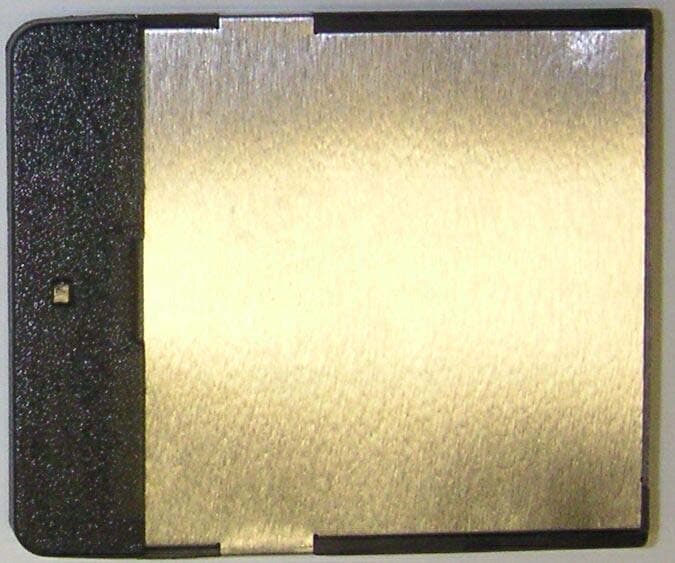
M4B6180210
Jun 22, 2005Wireless LAN Transmitter Module
Equipment Class
DTS - Digital Transmission System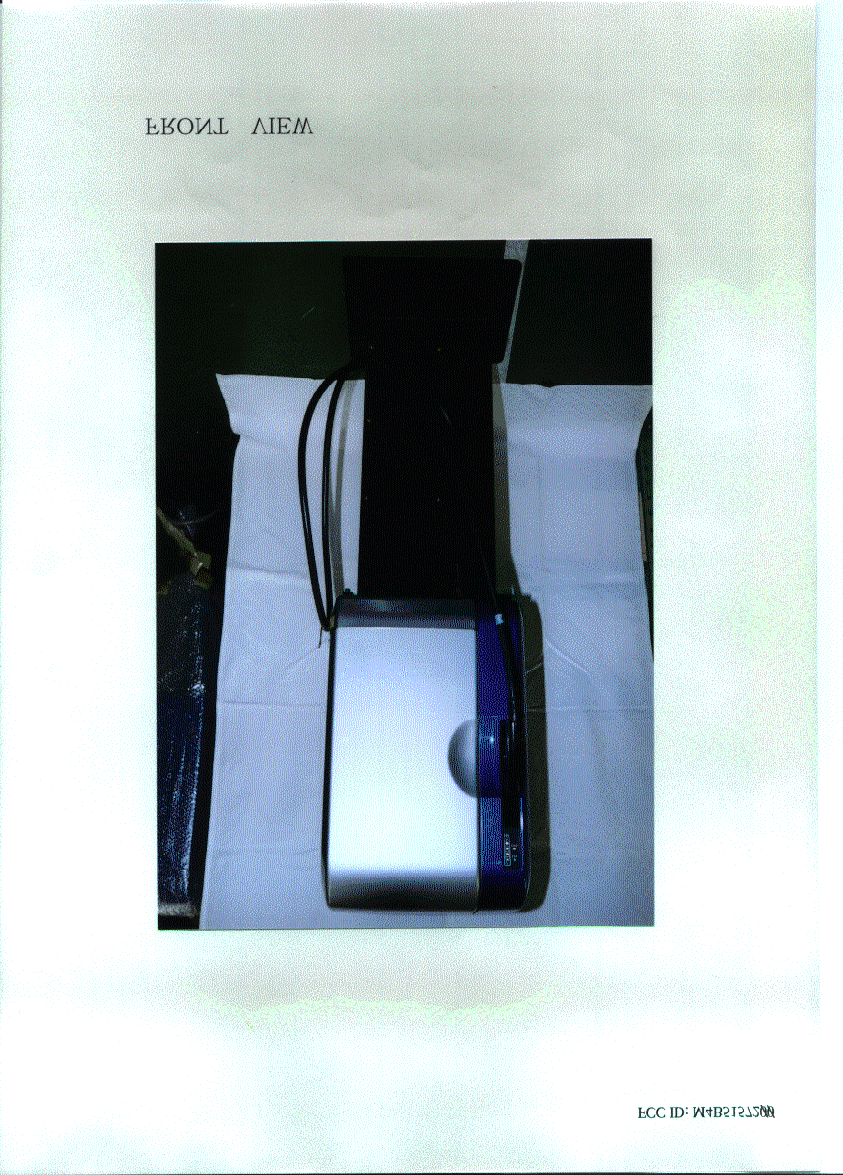
M4B5157000
Feb 21, 2000Electric Vehicle Charger
Equipment Class
DXX - Part 15 Low Power Communication Device TransmitterM4B5137000
Dec 16, 1997Electric Vehicle Charge Port
Equipment Class
DXT - Part 15 Low Power Transceiver, Rx Verified