M5MOPTOCOM
Optoelectronics Inc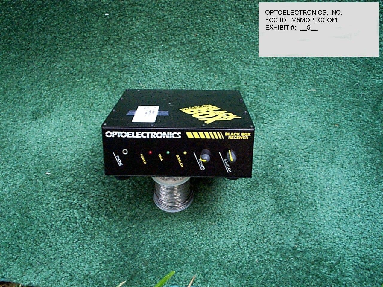
Click to zoom
Application Details
- Equipment Class
- CSR - Scanning Receiver
- Date of Grant
- Aug 03, 1998
- Application Purpose
- Original Equipment
- Date of Application
- Jul 01, 1998
- Frequency Range
- 30.00000000 - 824.00000000
- Company
- Optoelectronics Inc
- Country
- United States
Documents & Files
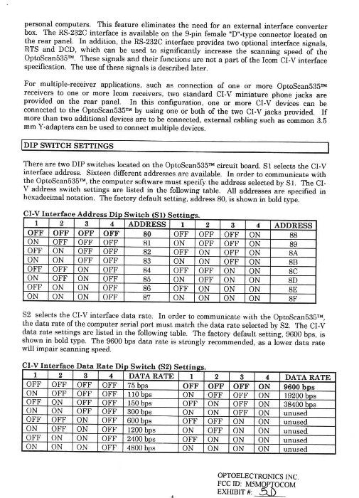
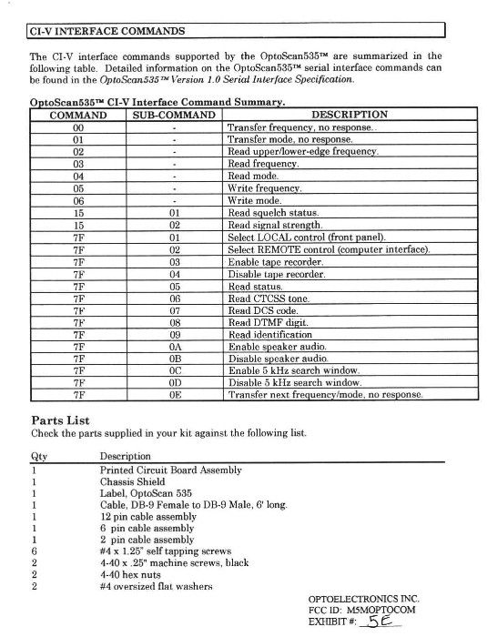
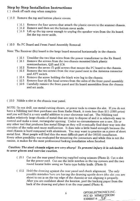
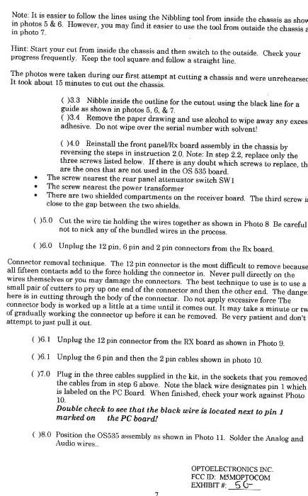
Document Text
Text extracted from the exhibit documents filed with the FCC. Open a document above to read the original.
Cover Letter(s)
Date: Tue, 16 Jun 1998 13:18:52 -0400 From: William Owen <[email protected]> Subject: OptoCom Part 15.121 Statement Sender: William Owen <[email protected]> To: Sharon <[email protected]> Statement of compliance with Part 15.121 by Optoelectronics Inc. for M5M-OPTOCOM Scanning Receiver The FCC ID No. M5M-OptoCom can not be modified by any means mentioned in Part 15.121 to enable Cellular receiption. The M5M-OptoCom will not Under any circumstances respond to any attempt to tune to a cellular frequency. No parts can be added to the control PC board that will enable cellular reception. No jumpers can be added and no PC foil traces can be cut to enable cellular reception. There is no possibility of a field modification to enable cellular reception by an expert individual. Method used to enable cellular reception revealed: No modification of already manufactured FCC compliant units can be done To enable Cellular reception. Units for export out of the United States And units that can be sold under 18USC2512 provisions are manufactured with a different microcontroller programmed with unique code. Furthermore, to provide positive control of un-blocked units, a guaranteed unique, silicon serial number device, will be installed that can not be duplicated or copied. The unique serial number will be registered with the qualified end user and kept on file. The silicon serial number is manufactured exclulsively by Dallas Semiconductor Corp. It is guaranteed to have a unique lazer coded 48 bit serial number. Optoelectronics will own and control the complete series of devices that could be used to enable cellular. These devices will not however function with M5M-OptoCom units that were manufactured as cellular blocked. This will make it impossible for units previously sold to be modified in the field for cellular coverage. A qualified 18USC2512 agency would need to return the cellular blocked unit in exchange for an unblocked unit because field modifications will not be possible. Optoelectronics has taken extrodinary steps to comply with PART 15.121. These steps are more costly to impliment and manufacture. Every Attempt has been made to make sure that no M5M-OptoCom units can be field modified, even with expert knowledge. Positive control of unblocked units has been achieved and those units can be traced to the original qualified purchaser through electronic serial number means. This will discourage the resale of unblocked units by cellular qualified individuals, companies, or agencies. APPLICANT: OPTOELECTRONICS. INC. FCC ID: M5MOPTOCOM PAGE #: 2A Voluntary Compliance with proposed Cellular Image requirements: The M5M-OptoCom receiver is in compliance with proposed limits on Cellular image reception due to the inherent image rejection in its Tripple conversion design. William P. Owen Engineering Manager Optoelectronics Inc. June 16, 1998 = APPLICANT: OPTOELECTRONICS, INC. FCC ID: M5MOPTOCOM EXHIBIT: 2B
Test Report
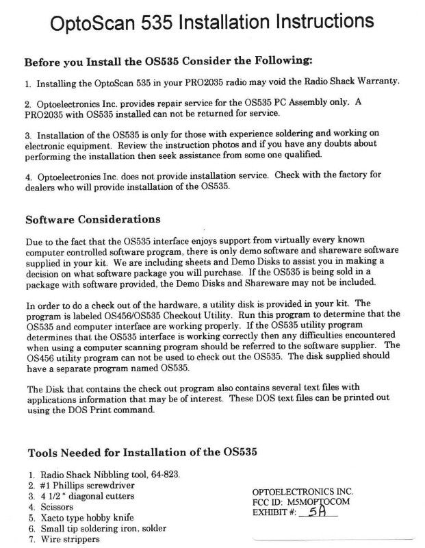
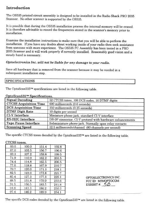
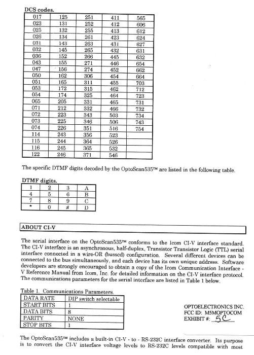
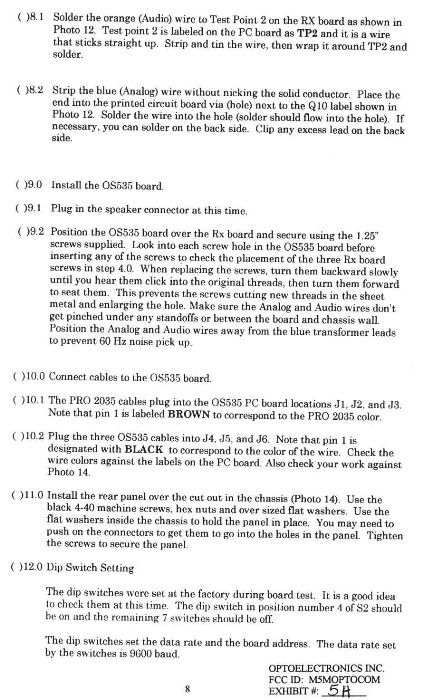
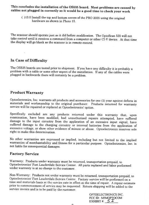
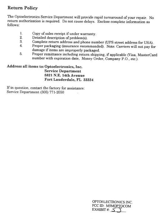
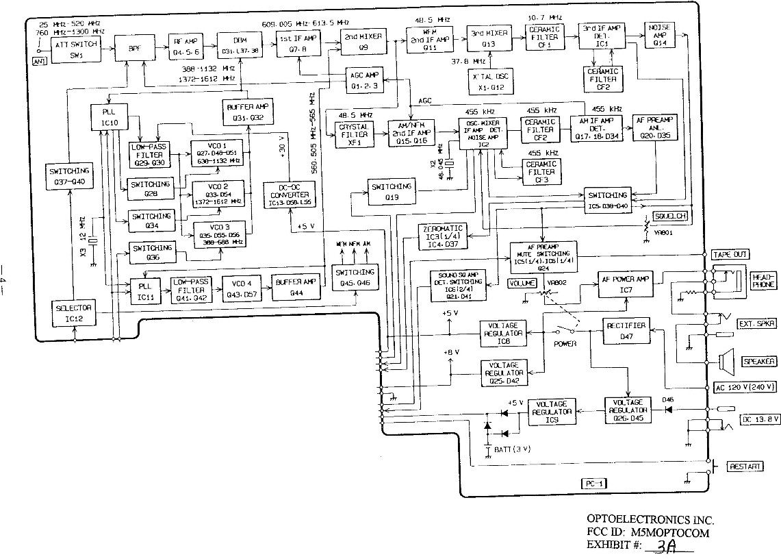
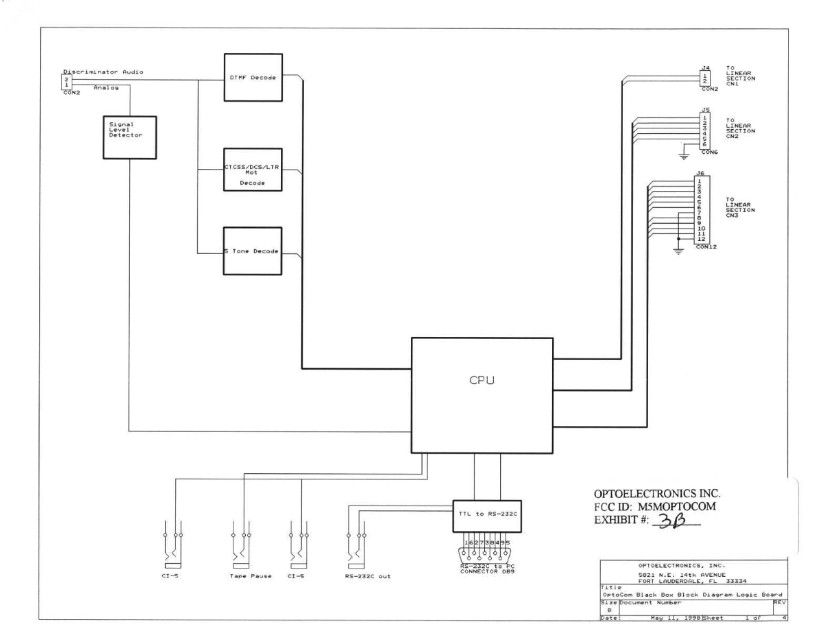
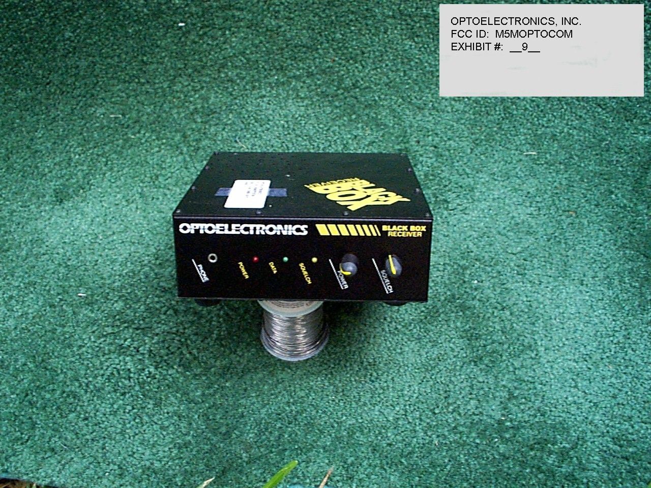
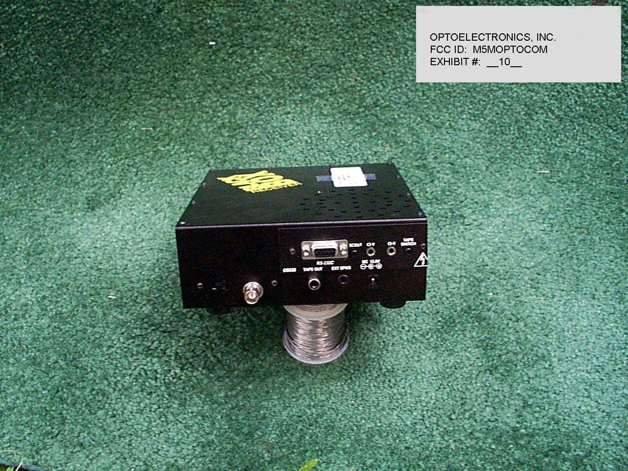
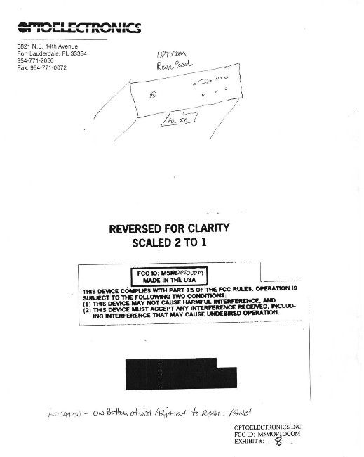
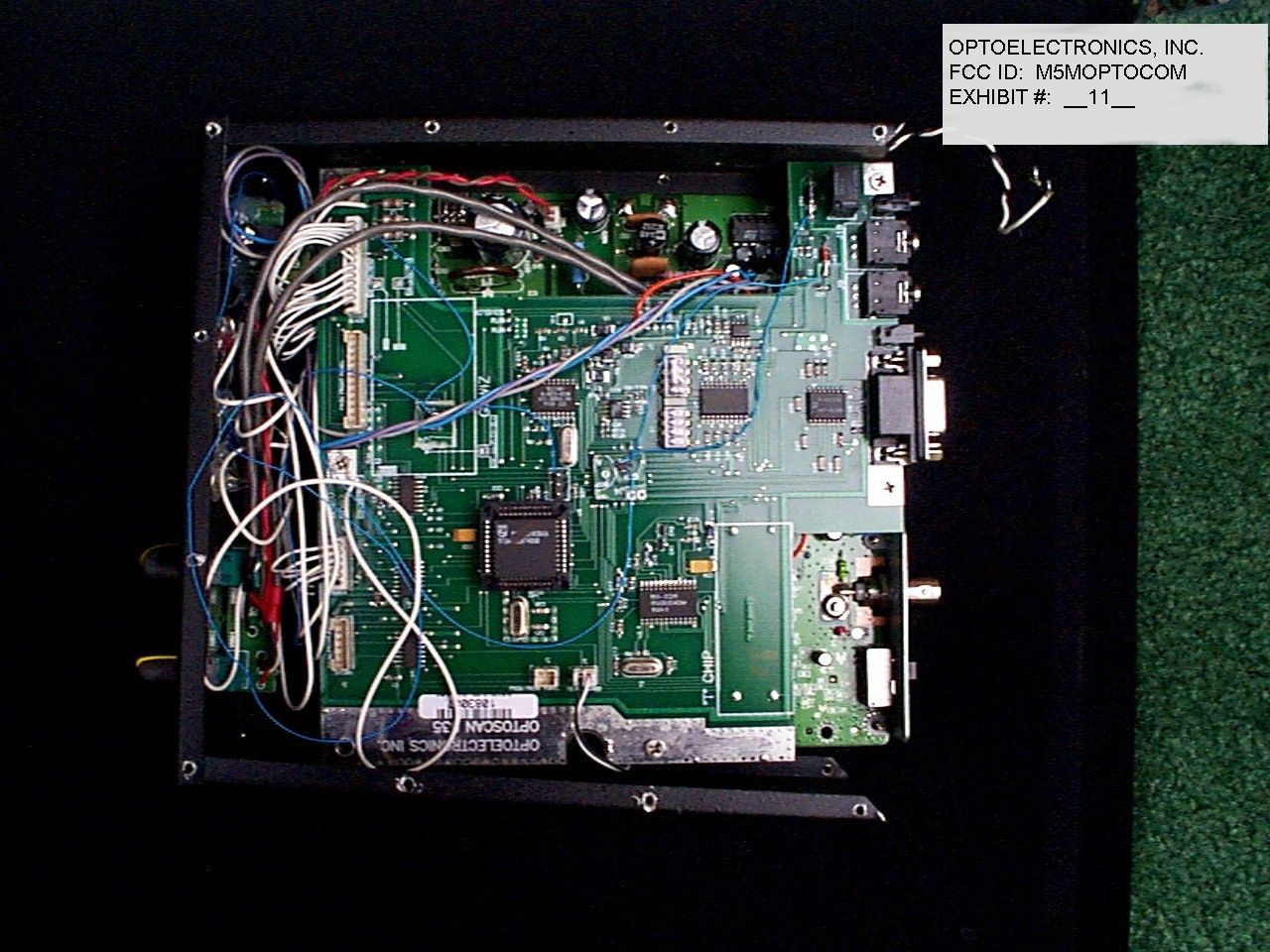
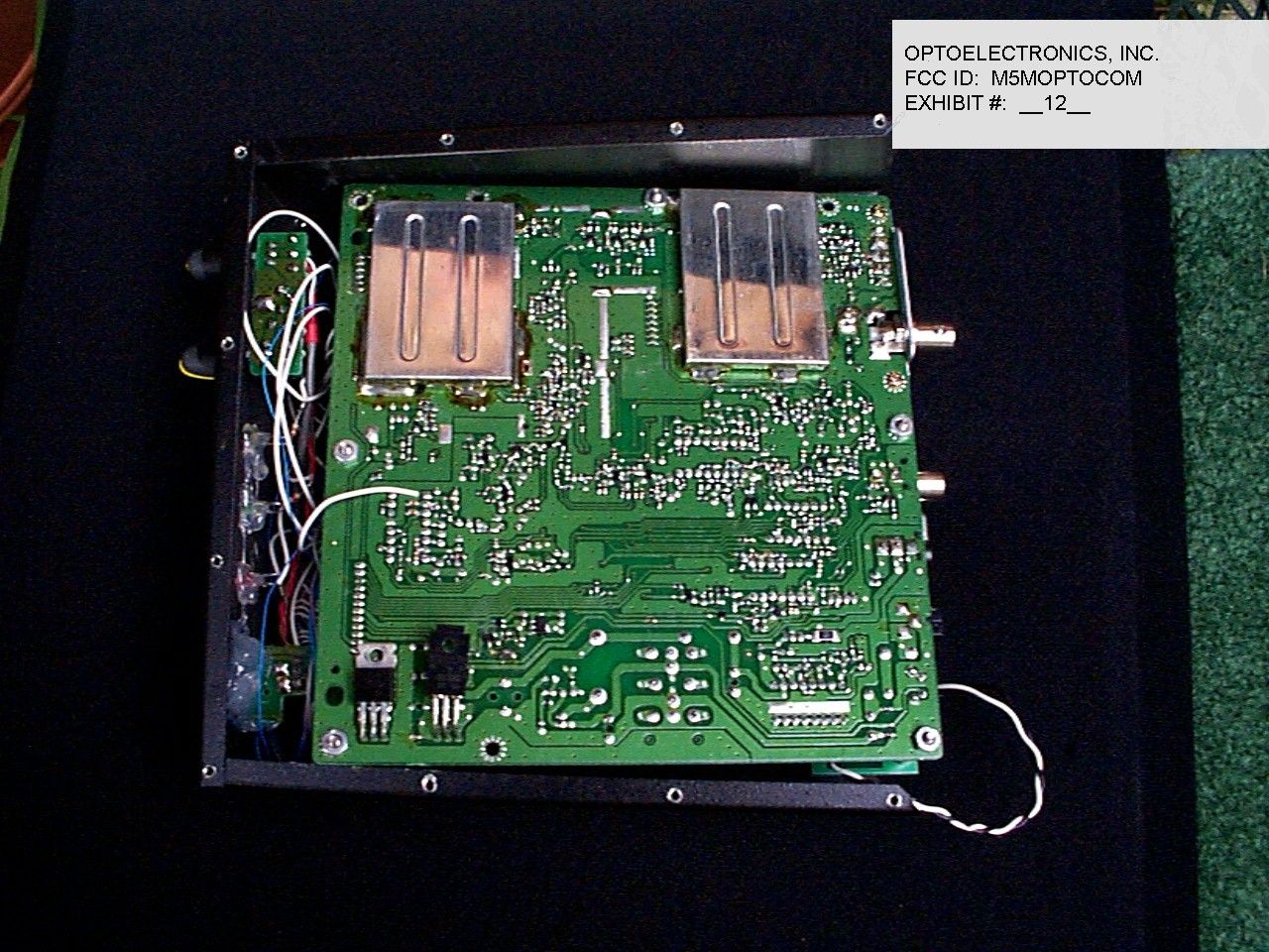
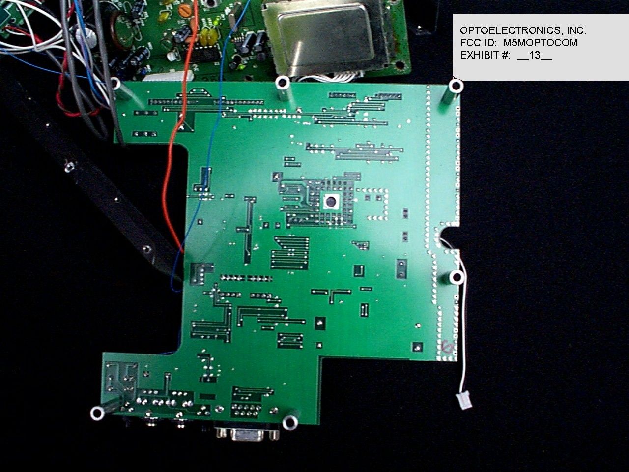
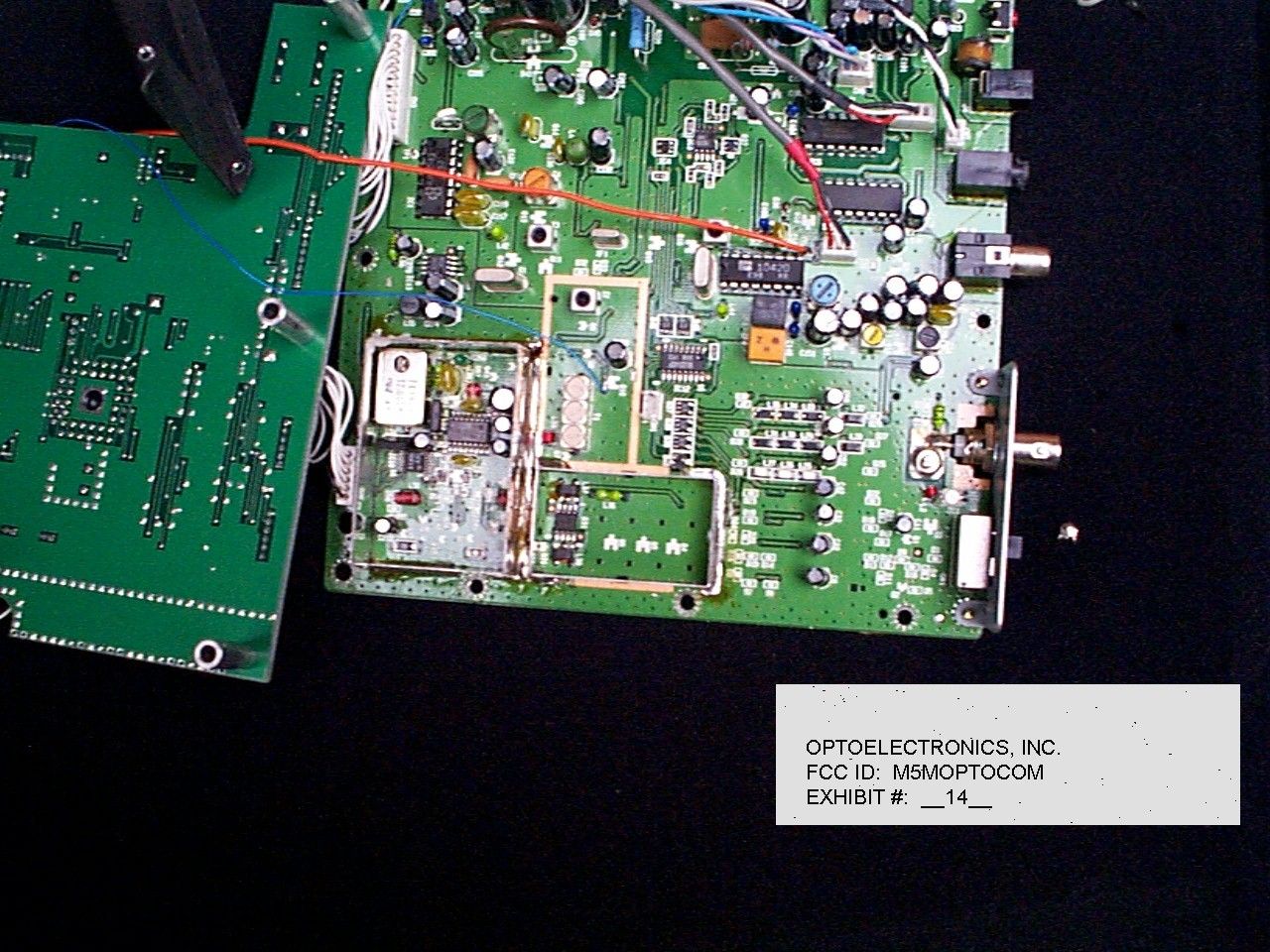
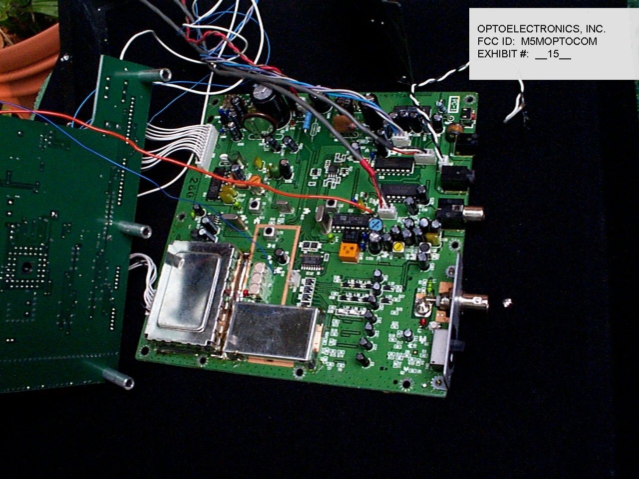
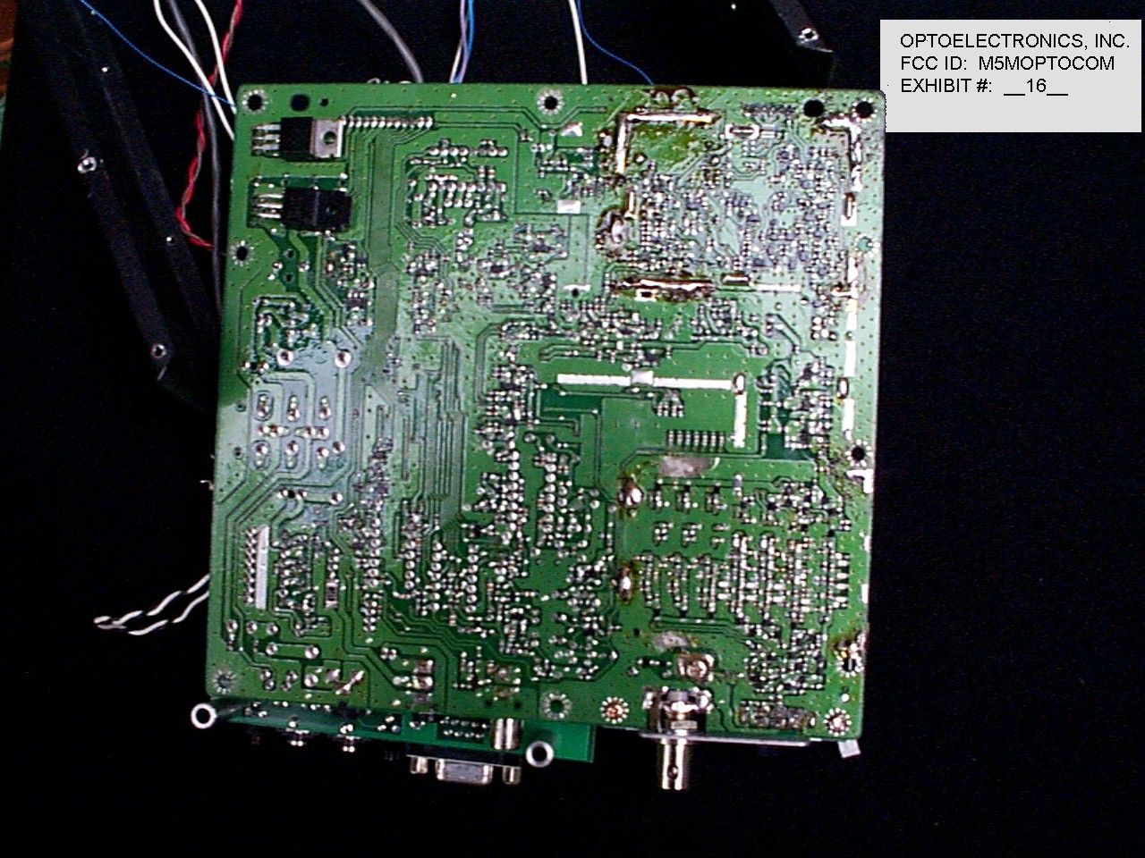
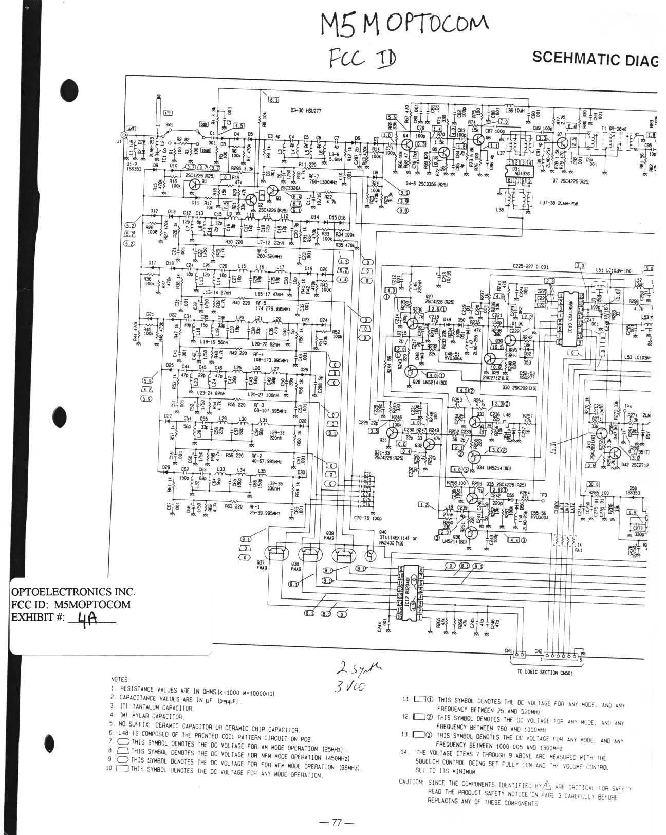
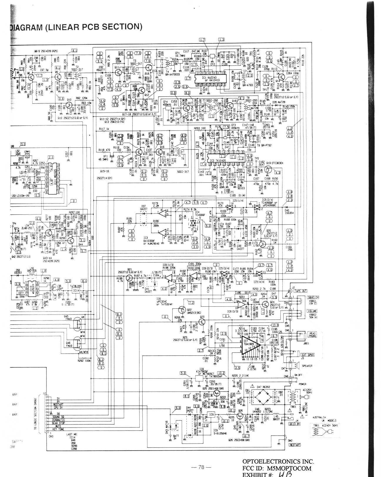
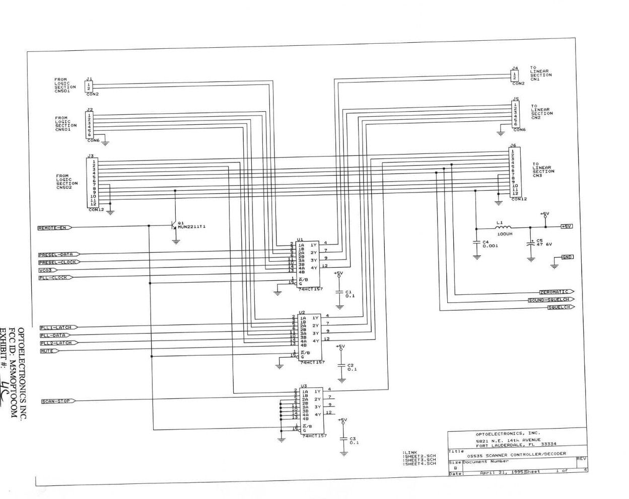
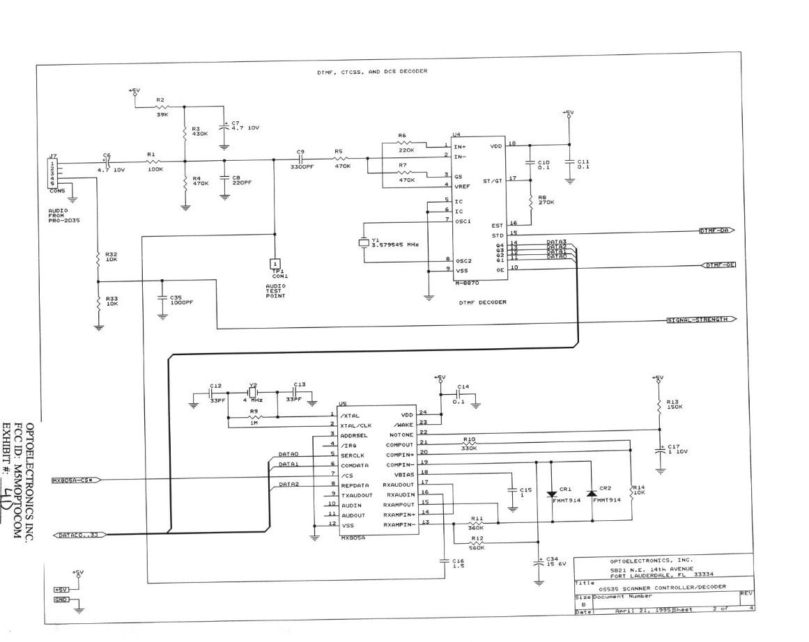
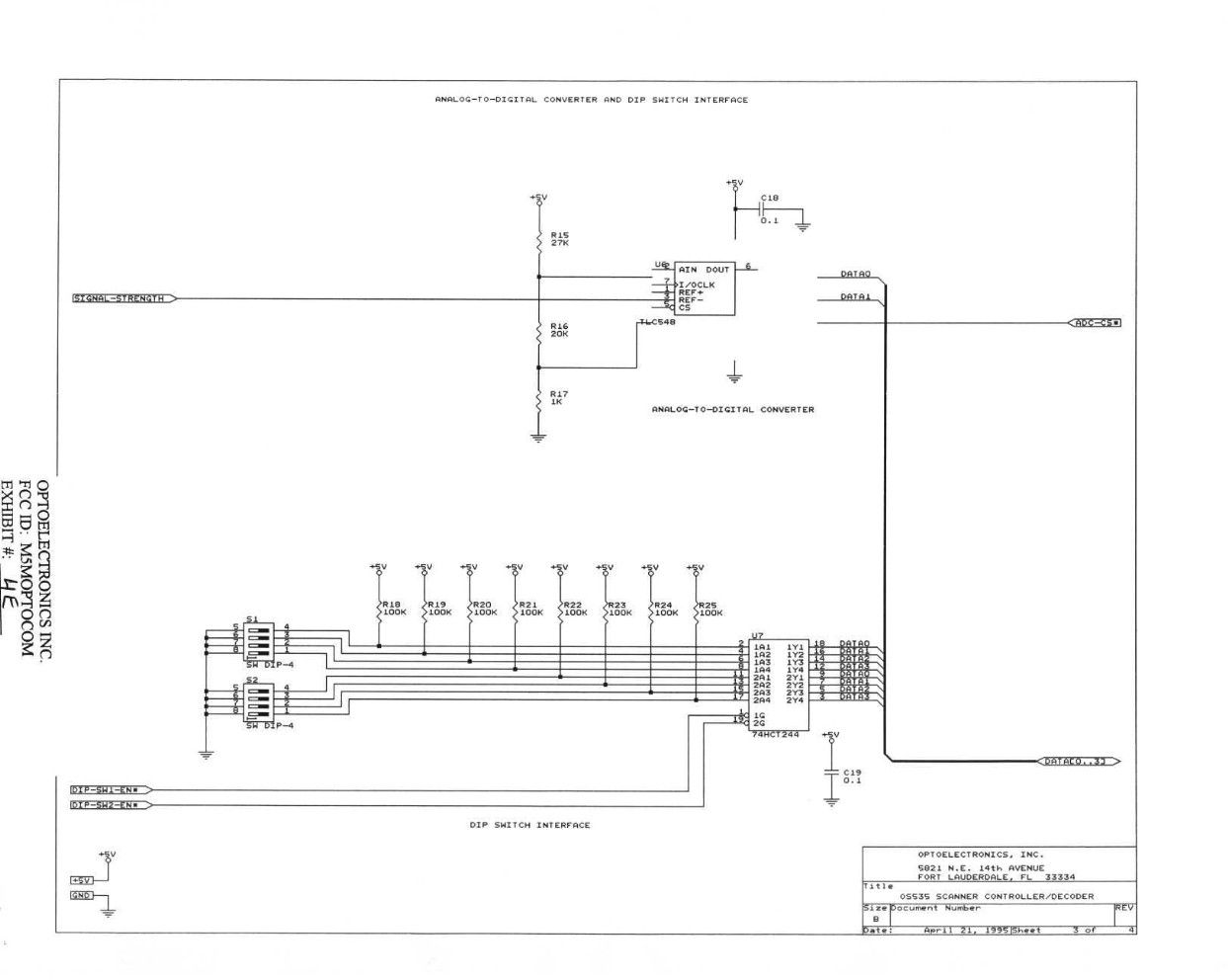
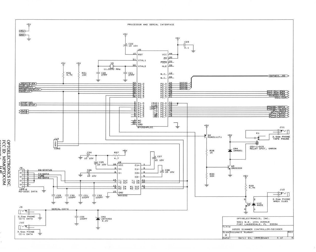
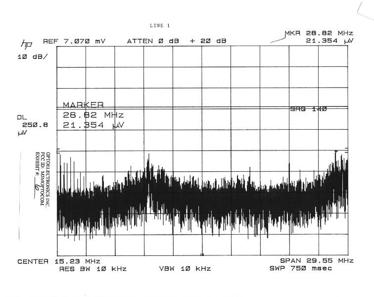
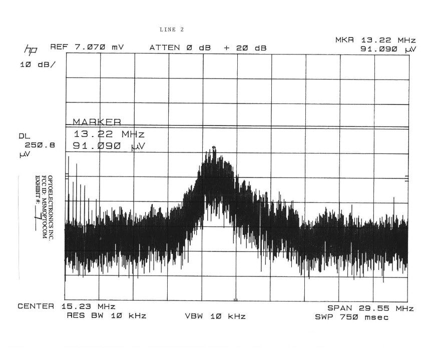
TABLE OF CONTENTS APPLICANT: OPTOELECTRONICS, INC. FCC ID: M5MOPTOCOM TEST REPORT CONTAINING: PAGE 1-2...........TEST PROCEDURE PAGE 2.............TEST PROCEDURE CONTD & CIRCUIT DESCRIPTION PAGE 3.............RADIATION INTERFERENCE TEST DATA PAGE 4.............RADIATION INTEFERENCE CONTD. AND POWERLINE CONDUCTED INTERFERENCE EXHIBIT ATTACHMENTS: EXHIBIT 1.............POWER OF ATTORNEY LETTER EXHIBIT 2A-2B.........15.121 COMPLIANCE STATEMENT EXHIBIT 3A-3B.........BLOCK DIAGRAMS EXHIBIT 4A-4F.........SCHEMATICS EXHIBIT 5A-5J.........INSTRUCTION MANUAL EXHIBIT 6.............POWERLINE CONDUCTED PLOT - LINE 1 EXHIBIT 7.............POWERLINE CONDUCTED PLOT - LINE 2 EXHIBIT 8.............FCC ID LABEL SAMPLE AND SKETCH OF LOCATION EXHIBIT 9.............EXTERNAL PHOTO - FRONT VIEW EXHIBIT 10............EXTERNAL PHOTO - BACK VIEW EXHIBIT 11............INTERNAL CPU BOARD - COMPONENT SIDE EXHIBIT 12............INTERNAL CPU BOARD - COPPER SIDE EXHIBIT 13............INTERNAL CPU BOARD - COPPER SIDE EXHIBIT 14............INTERNAL RX BOARD - COMPONENT SIDE EXHIBIT 15............INTERNAL RX BOARD - COMPONENT SIDE EXHIBIT 16............INTERNAL RX BOARD - COPPER SIDE APPLICANT: OPTOELECTRONICS, INC. FCC ID: M5MOPTOCOM REPORT #: F:\CUS\O\OPTO\OPT136C8.RPT PAGE: TABLE OF CONTENTS LIST APPLICANT: OPTOELECTRONICS, INC. FCC ID: M5MOPTOCOM TEST EQUIPMENT LIST 1. Spectrum Analyzer: Hewlett Packard 8566B, with preselector HP 85685A, & Quasi-Peak Adapter HP 8565OA, & HP 8449B OPT H02 Cal. 9/30/97 2. Eaton Biconnical Antenna Model 94455-1 20-200 MHz Serial No. 0997 Cal. 9/17/97 3. Electro-Metric Dipole Kit, 20-1000 MHz, Model TDA 25 cal. 5/15/97 4. Electro-Metric Horn 1-18 GHz, Model RGA-180, Cal. 9/24/97 5. Electro-Metric Antennas Model TDS-25-1, TDS-25-2, 9/3/97 6. Electro-Metric Line Impedance Stabilization Network Model No. EM-7821, Serial No. 101; 100KHz-30MHz 50uH. 9/30/97 7. Electro-Metric Line Impedance Stabilization Network Model No. EM-7820, Serial No. 2682; 10KHz-30MHz 50uH. 9/30/97 TEST PROCEDURE GENERAL: This report shall NOT be reproduced except in full without the written approval of TIMCO ENGINEERING, INC. RADIATION INTERFERENCE: The test procedure used was ANSI STANDARD C63.4-1992 using a HEWLETT PACKARD spectrum analyzer with a prese- lector. The bandwidth of the spectrum analyzer was 100 kHz with an appropriate sweep speed. The analyzer was calibrated in dB above a microvolt at the output of the antenna. The resolution bandwidth was 100KHz and the video bandwidth was 300KHz. The ambient temperature of the UUT was 79.7oF with a humidity of 64%. FORMULA OF CONVERSION FACTORS: The Field Strength at 3m was estab- lished by adding the meter reading of the spectrum analyzer (which is set to read in units of dBuV) to the antenna correction factor sup- plied by the antenna manufacturer. The antenna correction factors are stated in terms of dB. The gain of the Preselector was accounted for in the Spectrum Analyzer Meter Reading. Example: Freq (MHz) METER READING + ACF = FS 33 20 dBuV + 10.36 dB = 30.36 dBuV/m @ 3m POWER LINE CONDUCTED INTERFERENCE: The procedure used was ANSI STAN- DARD C63.4-1992 using a 50uH LISN. Both lines were observed. The bandwidth of the spectrum analyzer was 10kHz with an appro- priate sweep speed. The ambient temperature of the UUT was 79.7oF with a humidity of 64%. APPLICANT: OPTOELECTRONICS, INC. FCC ID: M5MOPTOCOM REPORT #: F:\CUS\O\OPTO\OPT136C8.RPT PAGE #: 1 TEST PROCEDURES CONTINUED APPLICANT: OPTOELECTRONICS, INC. FCC ID: M5MOPTOCOM ANSI STANDARD C63.4-1992 10.1.7 MEASUREMENT PROCEDURES: The unit under test was placed on a table 80 cm high and with dimensions of 1m by 1.5m. The table used for radiated measurements is capable of continuous rotation. When an emission was found, the table was rotated to produce the maximum signal strength. At this point, the antenna was raised and lowered from 1m to 4m. The antenna was placed in both the horizontal and vertical planes. The situation was similar for the conducted measurement except that the table did not rotate. The EUT was setup as described in ANSIC63.4-1992 with the EUT 40 cm from the vertical ground wall. CIRCUIT DESCRIPTION 2.1033 (b)(4) CIRCUIT DESCRIPTION: This unit is a near field radio receiver. The integrated circuit IC10 is a PLL which drives 4 different switches, Q29,Q30, Q28, Q34, Q36, which in turn drive 3 different VCO's. The VCO's Q27, Q33, Q35 then drive the tunable BPF and the 1st mixer. The 2nd PLL IC11 drives a low pass filter and VCO and buffer amplifier Q44 which feeds the 2nd mixer, Q9. From the 2nd mixer the signal goes to the 2nd IF amplifier Q11 and then to the 3rd mixer Q13. For AM signals the output of the 2nd mixer also drives the 2nd AM/IF amplifier Q15 & Q16 and then the oscillator/mixer IC2. FRom the 2nd AM mixer the signal is fed through a ceramic filter and then to an AM detector Q17. Integrated circuits IC4,5, & 6 per- forms amplification and most of the remaining receiver functions. ANTENNA & GROUND: This unit uses a short telescoping antenna for the receiving antenna. The antenna is self contained and there is no provision for connecting an external antenna. No ground connection is provided. The only ground used is the ground track on the PC Board. APPLICANT: OPTOELECTRONICS, INC. FCC ID: M5MOPTOCOM REPORT #: F:\CUS\O\OPTO\OPT136C8.RPT PAGE #: 2 APPLICANT: OPTOELECTRONICS, INC. FCC ID: M5MOPTOCOM NAME OF TEST: RADIATION INTERFERENCE RULES PART NUMBER: 15.109 REQUIREMENTS: 30 to 80 MHz: 40.0 dBuV/M @ 3 METERS 88 to 216 MHz: 43.5 dBuV/M 216 to 960 MHz: 46.0 dBuV/M ABOVE 960 MHz: 54.0 dBuV/M TEST RESULTS: A search was made of the spectrum from 30 to 1000 MHz and the measurements indicate that the unit DOES meet the FCC requirements. TEST DATA: TUNED EMISSION METER COAX FIELD FREQ. FREQUENCY READING LOSS A.C.F. STRENGTH MARGIN MHz MHz @ 3m dBuV dB dB dBuV/m@3m dB ANT. 27.15 33.22 9.30 0.25 10.37 19.92 20.08 V 27.15 564.38 13.90 1.60 19.82 35.32 10.68 V 27.15 639.99 20.90 1.60 20.98 43.48 2.52 …
Text truncated - open the document above for the full version.
Contact Information
Applicant
Linda R Hufft(President)
Technical Contact
Timco Engineering, Inc.S. S. Sanders
[email protected]888-472-2424
25355 W. Newberry Road · Newberry, Florida · United States
Non-Technical Contact
Timco Engineering, Inc.Sharon A Hoffman
[email protected]888-472-2424
Test Firm
Timco Engineering, Inc.Sid Sanders
Technical Specifications
| # | Rule Parts | Frequency Range | Power Output |
|---|---|---|---|
| 3 | 15B | 30 MHz - 824 MHz | - |
Other Applications from Optoelectronics Inc
M5MR11
Feb 02, 1998CSR - Scanning Receiver
Equipment Class
CSR - Scanning ReceiverM5MR50
May 12, 1997Scanner with serial port
Equipment Class
JBP - Part 15 Class B Computing Device Peripheral