M72-P0085.0 GHz WiFi Transmitter
HP Inc.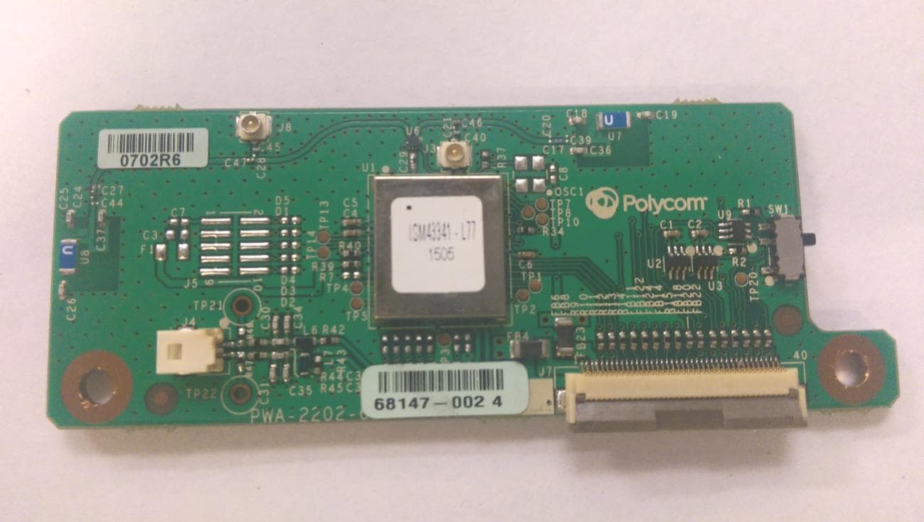
Click to zoom
Application Details
- Equipment Class
- NII - Unlicensed National Information Infrastructure TX
- Date of Grant
- Sep 10, 2015
- Application Purpose
- Original Equipment
- Date of Application
- Sep 10, 2015
- Equipment Note
- 5.0 GHz WiFi Transmitter
- Frequency Range
- 5745.00000000 - 5825.00000000
- Company
- HP Inc.
- Country
- United States
Documents & Files
Document Text
Text extracted from the exhibit documents filed with the FCC. Open a document above to read the original.
Users Manual
1 USER GUIDE September 2015 | 3725-20781-001D Polycom ® P008 Embedded ISM43341 SIP Application Module for the Polycom RealPresence Trio™ Solution Contents Features Specifications Output Power Levels Circuit Description PCB Integration FCC IC Compliance Statement Safety Information Features The Polycom P008 ISM43341 single-chip quad-radio device provides the highest level of integration for a mobile or handheld wireless system, with integrated dual band (2.4 GHz/ 5 GHz) IEEE 802.11 a/b/g and single-stream IEEE 802.11n MAC/baseband/radio, and Bluetooth 4.0. It integrates a low power NFC controller. The ISM43341 includes integrated power amplifiers, LNAs and T/R switches for the 2.4 GHz and 5 GHz WLAN bands, which greatly reduces the external part count, PCB footprint, and cost of the solution. The Polycom P008 ISM43341 is a fully approved module that complies with the following standards and certifications: ●ETSI EN 300 328 v1.9.1 ●ETSI EN 301 893 v1.7.1 ●ETSI EN 300 330 ●FCC Part 15 Unintentional emissions ●FCC Part 15.247 ●RSS103 I.C ●CISPR 22 ●ETSI EN 301 489-3 ●ETSI EN 301 489-17 ●EN 62311 Polycom, Inc. 2 Polycom P008 Embedded ISM43341 SIP Application Module – User Guide The ISM43341 application module transfers data signals by use of the radio frequency spectrum according to the WiFi, Bluetooth, and NFC standards. It is connected to the Polycom RealPresence Trio solution by a 40-pin flexible cable and is mounted with two machine screws. Specifications For specifications not listed in the following table, refer to the data sheet for the ISM43341 chip device. Radio Frequency Range WiFi Bluetooth NFC 2400MHz to 2483.5MHZ 5150MHz to 5250MHz 5250MHz to 5350MHz 5470MHz to 5725MHz 5725MHz to 5825MHz 2400MHz to 2483.5MHz 13.56MHz 1.8MHz bandwidth ModulationDynamic Frequency Selection (DFS) OFDM BT FHSS NFC 10% ASK, 100% ASK PowerPower over Ethernet (PoE) – also uses PoE+ with external DC-powered Power Injector Temperature Range0 to 40°C Size3.3” x 1.1” x 0.25” high Polycom, Inc. 3 Polycom P008 Embedded ISM43341 SIP Application Module – User Guide Output Power Levels Polycom, Inc. 4 Polycom P008 Embedded ISM43341 SIP Application Module – User Guide Circuit Description The Polycom P008 ISM43341 single-chip device provides a small form-factor solution with minimal external components to drive down cost for mass volumes, and allows for handheld device flexibility in size, form, and function. Comprehensive power management circuitry and software ensure the system can meet the needs of high mobile devices that require minimal power consumption and reliable operations. PCB Integration SDIO/I2S/UART Interface/Connection to Motherboard The RealPresence Trio radio module PCB employs a 40-pin flex circuit socket to connect to a motherboard 40-pin flex circuit cable. This interface is for the 3.3 VDC and 1.8Vpower sources and all necessary data lines to communicate with the radio module. Mounting The radio module has two mounting holes. The module should be placed down and fastened onto a motherboard containing two standoffs with metal screws. At the same time, the 40-pin flex cable connector will be engaged by locking the flex connector. Antenna The 2.4GHz/5GHz radio module PCB antennas are mounted permanently for WiFi/BT operation. No external WiFi/BT antennas are allowed. The NFC antenna loop is connected via a two-pin locking connector. Only the Polycom NFC antenna loop or equivalent is allowed. Polycom, Inc. 5 Polycom P008 Embedded ISM43341 SIP Application Module – User Guide FCC IC Compliance Statement This device complies with Part 15 of the FCC Rules. Operation is subject to the following two conditions: ●This device may not cause harmful interference. ●This device must accept any interference received, including interference that may cause undesired operation. ●Changes or modifications not expressly approved by the party responsible for compliance could void the users authority to operate the equipment User Information This equipment has been tested and found to comply with the limits for a Class B digital device, pursuant to Part 15 of the FCC Rules. These limits are designed to provide reasonable protection against harmful interference in a residential installation. This equipment generates, uses and can radiate radio frequency energy and, if not installed and used in accordance with the instructions, can cause harmful interference to radio communications. However, there is no guarantee that interference will not occur in a particular installation. If this equipment does cause harmful interference to radio or television reception, which can be determined by turning the equipment off and on, the user is encouraged to try to correct the interference by one or more of the following measures: ●Reorient or relocate the receiving antenna. ●Increase the separation between the equipment and receiver. ●Connect the equipment into an outlet on a circuit different from that to which the receiver is connected. ●Consult the dealer or an experienced radio/TV technician for help. This module is limited to OEM installation ONLY. The OEM integrator is responsible for ensuring that the end user has no manual instructions to remove or install the module. The module is limited to installation in mobile or fixed applications according to Part 2.1091(b). Separate approval is required for all other operating configurations, including portable configurations with respect to Part 2.1093 and different antenna configurations. The user’s manual or instruction manual for an intentional or unintentional radiator shall caution the user that changes or modifications not expressly approved by the party responsible for compliance could void the user's authority to operate the equipment. LE-LAN devices are restricted to indoor operation only in the band 5150MHz to 5250MHz. FCC / IC Canada Labeling of host device The modular transmitter is labeled with its own FCC and IC identification number. If the FCC or IC identification numb…
Text truncated - open the document above for the full version.
Cover Letter(s)
July 31, 2015 Timco Applications Examiner RE: Modular Approval for Polycom FCC ID: M72-P008 Dear Application Examiner: Regarding Part 15 Unlicensed Modular Transmitter Approval, the following requirements called out in FCC Public Notice DA 00-1407 are observed: 1) The modular transmitter must have its own RF shielding. This is intended to ensure that the module does not have to rely upon the shielding provided by the device into which it is installed in order for all modular transmitter emissions to comply with Part 15 limits. It is also intended to prevent coupling between the RF circuitry of the module and any wires or circuits in the device into which the module is installed. Such coupling may result in non-compliant operation. The Polycom model Polycom P008 SIP Application module is a completely self contained radio which has its own RF shielding on the RF section. No other RF shielding is required or implemented. 2) The modular transmitter must have buffered modulation/data inputs (if such inputs are provided) to ensure that the module will comply with Part 15 requirements under conditions of excessive data rates or overmodulation. The Polycom model Polycom P008 SIP Application module is a completely self contained radio which modulates its own RF transmitter. It controls the data flow to the transmitter section compliant with Part 15 requirements. 3) The modular transmitter must have its own power supply regulation. This is intended to ensure that the module will comply with Part 15 requirements regardless of the design of the power supplying circuitry in the device into which the module is installed. The module itself has a self-contained power regulator. It will supply only 3.3 VDC to the Polycom model Polycom P008 SIP Application module. 4) The modular transmitter must comply with the antenna requirements of Section 15.203 and 15.204(c). The antenna must either be permanently attached or employ a “unique” antenna coupler (at all connections between the module and the antenna, including the cable). Any antenna used with the module must be approved with the module, either at the time of initial authorization or through a Class II permissive change. The “professional installation” provision of Section 15.203 may not be applied to modules. For this application the Polycom model Polycom P008 SIP Application module employs a permanently attached antenna or has a unique antenna connector only. 5) The modular transmitter must be tested in a stand-alone configuration, i.e., the module must not be inside another device during testing. This is intended to demonstrate that the module is capable of complying with Part 15 emission limits regardless of the device into which it is eventually installed. Unless the transmitter module will be battery powered, it must comply with the AC line conducted requirements found in Section 15.207. AC or DC power lines and data input/output lines connected to the module must not contain ferrites, unless they will be marketed with the module (see Section 15.27(a)). The length of these lines shall be length typical of actual use or, if that length is unknown, at least 10 centimeters to insure that there is no coupling between the case of the module and supporting equipment. Any accessories, peripherals, or support equipment connected to the module during testing shall be unmodified or commercially available (see Section 15.31(i)). The module itself was tested while connected to Host Board or Laptop. The Host Board and Laptop was provided as a means to communicate with the radio through the serial connection. Nothing on the Host Board or Laptop contributes to the performance of the radio, therefore the radio is considered to have been tested in a standalone configuration. 6) The modular transmitter must be labeled with its own FCC ID number, and, if the FCC ID is not visible when the module is installed inside another device, then the outside of the device into which the module is installed must also display a label referring to the enclosed module. This exterior label can use wording such as the following: “Contains Transmitter Module FCC ID: XYZMODEL1” or “Contains FCC ID: XYZMODEL1.” Any similar wording that expresses the same meaning may be used. The Grantee may either provide such a label, an example of which must be included in the application for equipment authorization, or, must provide adequate instructions along with the module which explain this requirement. In the latter case, a copy of these instructions must be included in the application for equipment authorization. The Polycom model Polycom P008 SIP Application module consists of a printed circuit board, which is labeled with the FCC identification number. This PCB can be mounted in a host of devices and each device that this PCB utilizes will have the FCC ID number visible to the consumer. 7) The modular transmitter must comply with any specific rule or operating requirements applicable to the transmitter and the manufacturer must provide adequate instructions along with the module to explain any such requirements. A copy of these instructions must be included in the application for equipment authorization. For example, there are very strict operational and timing requirements that must be met before a transmitter is authorized for operation under Section 15.231. For instance, data transmission is prohibited, except for operation under Section 15.231(e), in which case there are separate field strength level and timing requirements. Compliance with these requirements must be assured. The Polycom model Polycom P008 SIP Application module comes equipped with embedded firmware that controls these parameters. 8) The modular transmitter must comply with any applicable RF exposure requirements. For example, FCC Rules in Sections 2.1091, 2.1093 and specific Sections of Part 15, including 15.319(i), 15.407(f), 15.253(f) and 15.255(g), require that Unlicensed PCS, UNII and millimeter wave devices perform…
Text truncated - open the document above for the full version.
Cover Letter(s)
Request for Confidentiality Date: ___July 31, 2015_____ Subject: Confidentiality Request for: ___FCC ID: M72-P008 IC:1849C-P008_ Pursuant to FCC 47 CRF 0.457(d) and 0.459 and IC RSP-100, Section 4, the applicant requests that a part of the subject FCC application be held confidential. Type of Confidentiality Requested Exhibit Short Term Permanent Block Diagrams Short Term External Photos Short Term Permanent Internal Photos Short Term Permanent Operation Description/Theory of Operation Short Term Permanent Parts List & Placement/BOM Short Term Permanent Tune-Up Procedure Short Term Permanent Schematics Short Term Test Setup Photos Short Term Permanent* User’s Manual Polycom has spent substantial effort in developing this product and it is one of the first of its kind in industry. Having the subject information easily available to "competition" would negate the advantage they have achieved by developing this product. Not protecting the details of the design will result in financial hardship. Permanent Confidentiality: The applicant requests the exhibits listed above as permanently confidential be permanently withheld from public review due to materials that contain trade secrets and proprietary information not customarily released to the public. NOTE for Industry Canada Applications: The applicant understands that until such time that IC distinguishes between Short Term and Permanent Confidentiality, either type of marked exhibit above will simply be marked Confidential when submitted to IC. Sincerely, By: __________________________ ___Sandi McEnery__- Agent (Signature/Title) (Print name)
External Photos
US Tech Test Report: FCC Part 15 Certification/ RSS 210 FCC ID: M72-P008 IC: 1849C-P008 Test Report Number: 15-0085 Issue Date: July 31, 2015 Customer: Polycom Inc. Model: P008 SIP Application Module Page 1 of 2 EXTERNAL PHOTOGRAPHS Figure 1. Top of EUT US Tech Test Report: FCC Part 15 Certification/ RSS 210 FCC ID: M72-P008 IC: 1849C-P008 Test Report Number: 15-0085 Issue Date: July 31, 2015 Customer: Polycom Inc. Model: P008 SIP Application Module Page 2 of 2 Figure 2. Bottom of EUT
Internal Photos
US Tech Test Report: FCC Part 15 Certification/ RSS 210 FCC ID: M72-P008 IC: 1849C-P008 Test Report Number: 15-0085 Issue Date: July 31, 2015 Customer: Polycom Inc. Model: P008 SIP Application module Page 1 of 2 ANTENNA PHOTOGRAPHS Figure 1. NFC Antenna for P008 SIP Application Module MFG: Polycom Type: Magnetic Wire Loop Gain: 0 dbi Connector: MOLEX 501330-0200 US Tech Test Report: FCC Part 15 Certification/ RSS 210 FCC ID: M72-P008 IC: 1849C-P008 Test Report Number: 15-0085 Issue Date: July 31, 2015 Customer: Polycom Inc. Model: P008 SIP Application module Page 2 of 2 Figure 2. Chip Antenna on EUT MFG: Unictron Technologies Corp. Type: Chip Gain: 1.4 dBi at 2.4 Ghz 2.3 dBi at 5 Ghz Connector: Direct Solder Chip Antennas
Internal Photos
US Tech Test Report: FCC Part 15 Certification/ RSS 210 FCC ID: M72-P008 IC: 1849C-P008 Test Report Number: 15-0085 Issue Date: July 31, 2015 Customer: Polycom Inc. Model: P008 SIP Application module Page 1 of 1 INTERNAL PHOTOGRAPHS Figure 1. EUT with Shielding Removed
RF Exposure Info
US Tech Test Report: FCC Part 15 Certification/ RSS 210 FCC ID: M72-P008 IC: 1849C-P008 Test Report Number: 15-0085 Issue Date: July 31, 2015 Customer: Polycom Inc. Model: P008 SIP Application module Page 1 of 1 MPE and SAR threshold requirements Highest Gain Antenna (2.4 GHz WiFi) = 1.4 dBi Peak Power (dBm)= 20.1 (highest measured output power level) Gain of Transmit Antenna = 1.4 dBi Distance = > 50 mm time based average= Duty Cycle = < 5% Total source based time average= (Pwr dBm) + (Ant gain dBi) * time based average 20.10 dBm + 1.4 dBi = 21.5 dBm (141.2 mW) * 0.05= 7.06 mW which is << less than 96 mW for FCC which is << less than 309 mW for IC which is << less than 20 mW for EU Highest Gain Antenna (5 GHz WiFi) = 2.3 dBi Peak Power (dBm)= 21.0 (highest measured output power level) Gain of Transmit Antenna = 2.3 dBi Distance = > 50 mm time based average= Duty Cycle = < 5% Total source based time average= (Pwr dBm) + (Ant gain dBi) * time based average 21.0 dBm + 2.3 dBi = 23.3 dBm (213.80 mW) * 0.05= 10.69 mW which is << less than 62 mW for FCC which is << less than 106 mW for IC which is << less than 20 mW for EU
Test Report
Page 1 of 214 Application For Part 2, Subpart J, Paragraph 2.907 Equipment Authorization of Certification for an Intentional Radiator per Part 15, Subpart E, paragraphs 15.401, 15.403, 15.405 and 15.407 And RSS-247 Issue 1 of Industry Canada For the Polycom Inc. Model: P008 FCC ID: M72-P008 IC: 1849C-P008 UST Project: 15-0086 Issue Date: July 7, 2015 Total Pages in This Report: 214 3505 Francis Circle Alpharetta, GA 30004 PH: 770-740-0717 Fax: 770-740-1508 www.ustech-lab.com Page 2 of 214 I certify that I am authorized to sign for the Test Agency and that all of the statements in this report and in the Exhibits attached hereto are true and correct to the best of my knowledge and belief: US TECH (Agent Responsible For Test): By: Alan Ghasiani Name: Title: Compliance Engineer – President Date July 7, 2015 This report shall not be reproduced except in full. This report may be copied in part only with the prior written approval of US Tech. The results contained in this report are subject to the adequacy and representative character of the sample provided. This report must not be used to claim product certification, approval, or endorsement by NVLAP, NIST or any agency of the Federal Government. 3505 Francis Circle Alpharetta, GA 30004 PH: 770-740-0717 Fax: 770-740-1508 www.ustech-lab.com US Tech Test Report: FCC Part 15 Certification/ RSS 247 FCC ID: M72-P008 IC: 1849C-P008 Test Report Number: 15-0086 Issue Date: July 7, 2015 Customer: Polycom Inc. Model: P008 Page 3 of 214 MEASUREMENT TECHNICAL REPORT COMPANY NAME: Polycom Inc. MODEL: P008 FCC ID: M72-P008 IC: 1849C-P008 DATE: July 7, 2015 This report concerns (check one): Original grant X Class II change Equipment type: 5.15-5.35 GHz, 5.47-5.75 GHz, and 5.725- 5.85 GHz Transmitter Deferred grant requested per 47 CFR 0.457(d)(1)(ii)? yes_____ No X If yes, defer until: ______N/A___________ date agrees to notify the Commission by N/A date of the intended date of announcement of the product so that the grant can be issued on that date. Report prepared by: US Tech 3505 Francis Circle Alpharetta, GA 30004 Phone Number: (770) 740-0717 Fax Number: (770) 740-1508 US Tech Test Report: FCC Part 15 Certification/ RSS 247 FCC ID: M72-P008 IC: 1849C-P008 Test Report Number: 15-0086 Issue Date: July 7, 2015 Customer: Polycom Inc. Model: P008 Page 4 of 214 Table of Contents Paragraph Title Page 1 General Information ............................................................................................ 12 1.1 Purpose of this Report .................................................................................... 12 1.2 Characterization of Test Sample .................................................................... 12 1.3 Product Description ........................................................................................ 12 1.4 Configuration of Tested System ..................................................................... 12 1.5 Test Facility .................................................................................................... 13 1.6 Related Submittals ......................................................................................... 13 2 Tests and Measurements ................................................................................... 15 2.1 Test Equipment .............................................................................................. 15 2.2 Modifications to EUT Hardware ...................................................................... 16 2.3 Number of Measurements for Intentional Radiators (15.31(m)) ..................... 16 2.4 Frequency Range of Radiated Measurements (Part 15.33) ........................... 16 2.4.1 Intentional Radiator .................................................................................. 16 2.4.2 Unintentional Radiator ............................................................................. 17 2.5 Measurement Detector Function and Bandwidth (CFR 15.35) ....................... 17 2.5.1 Detector Function and Associated Bandwidth ......................................... 17 2.5.2 Corresponding Peak and Average Requirements .................................... 17 2.5.3 Pulsed Transmitter Averaging .................................................................. 17 2.6 EUT Antenna Requirements (CFR 15.203) .................................................... 18 2.7 Restricted Bands of Operation (Part 15.205).................................................. 18 2.8 Transmitter Duty Cycle (CFR 35 (c)) .............................................................. 19 2.9 Intentional Radiator, Power Line Conducted Emissions (CFR 15.207) .......... 21 2.10 Intentional Radiator, Radiated Emissions (CFR 15.209, 15.407(d)) (IC RSS 247, 6.2) ............................................................................................................... 23 2.11 Band Edge Measurements – (CFR 15.407 (b)) ............................................ 91 2.12 Unwanted Emissions in the Restricted Bands (CFR 15.205, 15.209) ........ 124 2.13 Six (6) dB Bandwidth per CFR 15.407(e), .................................................. 143 2.14 99% Occupied Bandwidth (15.407(a) (5), IC RSS 247, 6.4) ...................... 148 2.15 Maximum Peak Conducted Output Power (CFR 15.407 (a) (1,2,3)) .......... 167 2.16 Power Spectral Density (CFR 15.407(a) (5)) (IC RSS 247 5.1, 5.2) ........... 190 2.17 Frequency Stability ..................................................................................... 212 2.18 Radiated Digital Emissions (Co-Location) .................................................. 214 2.19 Measurement Uncertainty .......................................................................... 214 2.19.1 Conducted Emissions Measurement Uncertainty ................................ 214 2.19.2 Radiated Emissions Measurement Uncertainty ................................... 214 US Tech Test Report: FCC Part 15 Certification/ RSS 247 FCC ID: M72-P008 IC: 1849C-P008 …
Text truncated - open the document above for the full version.
Test Report
Report No.: HCT-R-1508-F010 Model: P008 Page 2 of 23 F-01P-02-014 (Rev.00) FCC ID: M72-P008/IC:1849C-P008 HCT Co.,Ltd. Version TEST REPORT NO. DATE DESCRIPTION HCT-R-1508-F010 August 26, 2015 - First Approval Report Report No.: HCT-R-1508-F010 Model: P008 Page 3 of 23 F-01P-02-014 (Rev.00) FCC ID: M72-P008/IC:1849C-P008 HCT Co.,Ltd. Table of Contents 1. GENERAL INFORMATION .......................................................................................................................... 4 2. EUT DESCRIPTION ..................................................................................................................................... 4 3. SCOPE ......................................................................................................................................................... 5 4. INSTRUMENT CALIBRATION..................................................................................................................... 5 5. FACILITIES AND ACCREDITATIONS ......................................................................................................... 5 5.1 FACILITIES ......................................................................................................................................... 5 5.2 EQUIPMENT ....................................................................................................................................... 5 6. SUMMARY OF TEST RESULTS ................................................................................................................. 6 7. DESCRIPTION OF DYNAMIC FREQUENCY SELECTION TEST.............................................................. 7 7.1 APPLICABILITY ................................................................................................................................. 7 7.2 REQUIREMENTS................................................................................................................................ 8 7.3 DFS DETECTION THRESHOLD VALUES .................................................................................... 10 7.4 PARAMETERS OF DFS TEST SIGNALS ...................................................................................... 11 7.5 TEST AND MEASUREMENT SYSTEM ......................................................................................... 13 7.6 DESCRIPTION OF EUT .................................................................................................................. 15 7.7 UNII2A TEST RESULT ................................................................................................................... 16 7.8 UNII2C TEST RESULT ................................................................................................................... 21 8. LIST OF TEST EQUIPMENT ................................................................................................................... 23 Report No.: HCT-R-1508-F010 Model: P008 Page 4 of 23 F-01P-02-014 (Rev.00) FCC ID: M72-P008/IC:1849C-P008 HCT Co.,Ltd. 1. GENERAL INFORMATION Applicant: Polycom, Inc. Address: 6001 America Center Dr., San Jose, CA 95002, USA FCC ID: IC: M72-P008 1849C-P008 EUT Type: Leaf Module Model name(s): LSM43341 Date(s) of Tests: June 30, 2015 ~ July 11, 2015 Place of Tests: HCT Co., Ltd. 74, Seoicheon-ro 578beon-gil, Majang-myeon, Icheon-si, Gyeonggi-do, Korea. (IC Recognition No. : 5944A-3) 2. EUT DESCRIPTION FCC/IC Model Name P008 EUT Type Leaf Module Power Supply DC5.0 V Frequency Range TX_20 MHz BW: 5180 MHz - 5240 MHz (UNII 1)/ 5260 MHz - 5320 MHz (UNII 2A)/ 5500 MHz - 5700 MHz (UNII 2C)/ 5745 MHz - 5825 MHz (UNII 3) RX_20 MHz BW: 5180 MHz - 5240 MHz (UNII 1)/ 5260 MHz - 5320 MHz (UNII 2A)/ 5500 MHz - 5700 MHz (UNII 2C)/ 5745 MHz - 5825 MHz (UNII 3) Modulation Type OFDM(802.11a, 802.11n, 802.11ac) Antenna Specification Manufacturer:Unictron Technologies Corp. Antenna type:Chip Antenna Peak Gain : 2.3 dBi (5260~5320 UNII2A BAND) / 2.3 dBi (5500~5700 UNII2C BAND) Report No.: HCT-R-1508-F010 Model: P008 Page 5 of 23 F-01P-02-014 (Rev.00) FCC ID: M72-P008/IC:1849C-P008 HCT Co.,Ltd. 3. SCOPE This report has been prepared to demonstrate compliance with the requirements for Dynamic Frequency Selection(DFS) as stated in KDB 905462 D02 v01 and Industry Canada RSS 247 specifications. Testing was performed P008 in accordance with the measurement procedure described in Appendix B of FCC KDB 905462 D02 v01 . As of July 20, 2007 all devices operating in the UNII 2A Band and /or the UNII 2C Bands must comply with the DFS requirements. 4. INSTRUMENT CALIBRATION The measuring equipment, which was utilized in performing the tests documented herein, has been calibrated in accordance with the manufacturer's recommendations for utilizing calibration equipments, which is traceable to recognized national standards. 5. FACILITIES AND ACCREDITATIONS 5.1 FACILITIES The SAC(Semi-Anechoic Chamber) and conducted measurement facility used to collect the radiated data are located at the 74, Seoicheon-ro 578beon-gil, Majang-myeon, Icheon-si, Gyeonggi-do, Korea The site is constructed in conformance with the requirements of ANSI C63.4. (Version :2014) and CISPR Publication 22. Detailed description of test facility was submitted to the Commission and accepted dated July 07, 2015 (Registration Number: 90661) 5.2 EQUIPMENT Radiated emissions are measured with one or more of the following types of Linearly polarized antennas: tuned dipole, bi-conical, log periodic, bi-log, and/or ridged waveguide, horn. Spectrum analyzers with pre-selectors and quasi-peak detectors are used to perform radiated measurements. Conducted emissions are measured with Line Impedance Stabilization Networks and EMI Test Receivers. Calibrated wideband preamplifiers, coaxial cables, and coaxial attenuators are also used for making measurements. All receiving equipment conforms to CISPR Publication 16-1, “Radio Interference Measuring Apparatus and Measurement Methods.” Report No.: HCT-R-1508-F010 Model…
Text truncated - open the document above for the full version.
Contact Information
Applicant
Richard Tarsio(US/CAN TRSE Worldwide Technical Regulations)
Test Firm
US TechGeorge Yang
Technical Specifications
| # | Rule Parts | Frequency Range | Power Output |
|---|---|---|---|
| 4 | 15E | 5.75 GHz - 5.83 GHz | 76.00 mW |
Other Applications from HP Inc.
M72-EDV250P
Jan 19, 2026Poly Edge V250 Plus
Equipment Class
NII - Unlicensed National Information Infrastructure TXM72-EDV850
Jan 15, 2026Poly Edge V850
Equipment Class
DSS - Part 15 Spread Spectrum TransmitterM72-EDV650
Dec 17, 2025Poly Edge V650
Equipment Class
DTS - Digital Transmission SystemM72-STX72R
Aug 25, 2024Video Bar
Equipment Class
NII - Unlicensed National Information Infrastructure TX
M72-P033
Jan 31, 2023Video CODEC
Equipment Class
DTS - Digital Transmission System