M72-P030Poly TC10
HP Inc.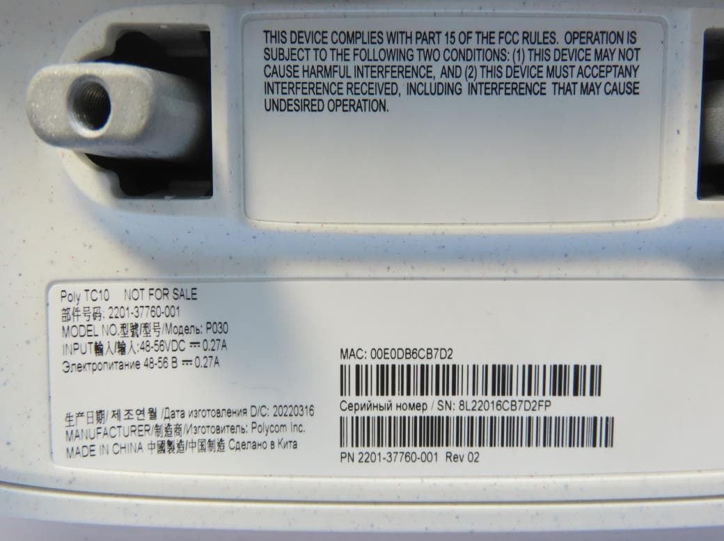
Click to zoom
Application Details
- Equipment Class
- NII - Unlicensed National Information Infrastructure TX
- Date of Grant
- Aug 29, 2022
- Application Purpose
- Original Equipment
- Date of Application
- Aug 29, 2022
- Equipment Note
- Poly TC10
- Frequency Range
- 5745.00000000 - 5825.00000000
- Company
- HP Inc.
- Country
- United States
Documents & Files
Document Text
Text extracted from the exhibit documents filed with the FCC. Open a document above to read the original.
Users Manual
1 Poly TC10 This document covers Poly TC10 (Models P030 and P030NR). Service Agreements Please contact your Poly Authorized Reseller for information about service agreements applicable to your product. Safety, Compliance, and Disposal Information ● This equipment is intended for indoor use only. ● This equipment is not intended to be directly connected to outdoor cables. ● Do not spray liquids directly onto the system when cleaning. Always apply the liquid first to a static- free cloth. ● Do not immerse the system in any liquids or place any liquids on it. ● Do not disassemble this system. To reduce the risk of shock and to maintain the warranty on the system, a qualified technician must perform service or repair work. ● There are no user serviceable parts inside this product. ● This equipment is not intended to be operated by children. ● Users must not service any parts in compartments that require a tool to access. ● This equipment should be used only on even surfaces. ● Keep ventilation openings free from any obstructions. ● The ambient operating temperature rating of this equipment is 0-40°C and should not be exceeded. ● In order to remove all power from this unit, disconnect all power cables, including any USB or Power over Ethernet ( PoE) cables. ● If the product is powered using PoE, you must use an appropriately rated and approved networking device compliant with IEEE 802.3af, or the power injector identified for use with this product. Operating Ambient Temperature ● Operating temperature: +32 to 104°F (0 to +40°C) ● Relative humidity: 15% to 80%, non-condensing ● Storage temperature: -4 to 140°F (-20 to +60°C) September 2022 | 3725-37724-001A SAFETY AND REGULATORY NOTICES Safety and Regulatory Notices | Poly TC10 2 Installation Instructions Installation must be performed in accordance with all relevant national wiring rules. L’Installation doit être exécutée conformément à tous les règlements nationaux applicable au filage électrique. When using Power over Ethernet (PoE), the equipment is to be connected only to PoE networks without connections to the outside plant. Lorsque vous utilisez une alimentation électrique par cable ethernet (PoE - Power over Ethernet), l'équipement doit être connecté uniquement aux réseaux PoE sans connexions vers l'extérieur de l'usine. USA Part 15 FCC Rules This device is compliant with Part 15 of the FCC Rules. Operation is subject to the following two conditions: ●This device may not cause harmful interference. ●This device must accept any interferences received, including interference that may cause undesired operation. In accordance with part 15 of the FCC rules, the user is cautioned that any changes or modifications not expressly approved by Poly could void the user’s authority to operate the equipment. This equipment has been tested and found to comply with the limits for a Class A digital device, pursuant to part 15 of the FCC Rules. These limits are designed to provide reasonable protection against harmful interference when the equipment is operated in a commercial environment. This equipment generates, uses, and can radiate radio frequency energy and, if not installed and used in accordance with the instruction manual, may cause harmful interference to radio communications. Operation of this equipment in a residential area is likely to cause harmful interference in which case the user will be required to correct the interference at their own expense. FCC Caution: Any changes or modifications not expressly approved by the party responsible for compliance could void the user's authority to operate this equipment. This transmitter must not be co-located or operating in conjunction with any other antenna or transmitter. Responsible P arty issuing FCC Supplier’s Declaration of Conformity Polycom, Inc. 6001 America Center Drive San Jose, CA 95002 USA [email protected]. Safety and Regulatory Notices | Poly TC10 3 Radiation Exposure Statement The antenna used for this transmitter must be installed to provide a separation distance of at least 20 centimeters from all persons and must not be co-located or operating in conjunction with any other antenna or transmitter. This device with its antenna complies with FCC’s RF radiation exposure limits set forth for an uncontrolled environment. To maintain compliance, this transmitter must not be co-located or operating in conjunction with any other antenna or transmitter. Canada Industry Canada Statement This device complies with RSS247 of the Industry Canada rules and also with ISED’s license-exempt RSS regulations. Operation is subject to the two following conditions: (1) This device does not cause harmful interference. (2) This device must accept any interference received, including interference that may cause undesired operation. Le présent appareil est conforme aux CNR d' ISED applicables aux appareils radio exempts de licence. L'exploitation est autorisée aux deux conditions suivantes: (1) le dispositif ne doit pas produire de brouillage préjudiciable, et (2) ce dispositif doit accepter tout brouillage reçu, y compris un brouillage susceptible de provoquer un fonctionnement indésirable. This device for operation in band 5150-5250 MHz is only for indoor use to reduce the potential for harmful interference to co-channel mobile satellite systems. Cet appareil destiné à fonctionner dans la bande 5150-5250 MHz est uniquement destiné à une utilisation en intérieur afin de réduire le potentiel d'interférences nuisibles aux systèmes satellites mobiles cocanaux. This Class [A] digital apparatus complies with Canadian ICES-003. Cet appareil numérique de la classe [A] est conforme à la norme NMB-003 du Canada. Certification Number IC: 1849C-P030 Radiation Exposure Statement This equipment complies with ISED radiation exposure limits set forth for an uncontrolled environment. This equipment should be installed and operated with greater than 20 cm between the radiator and your body. Safety and Regulatory Notice…
Text truncated - open the document above for the full version.
Users Manual
1.0 | March 2022 | Poly TC10 Getting Help For more information about installing, configuring, and administering Poly/Polycom products or services, go to Poly Online Support Center. Poly 345 Encinal Street Santa Cruz, California 95060 © 2022 Poly. Bluetooth is a registered trademark of Bluetooth SIG, Inc. All other trademarks are the property of their respective owners. 2 Contents Contents ............................................................................................................ 2 Before You Begin ............................................................................................. 3 Audience, Purpose, and Required Skills ................................................................... 3 Product Terminology Used in this Guide ................................................................... 3 Related Poly and Partner Resources ........................................................................ 3 Getting Started ................................................................................................. 5 Poly TC10 Overview ................................................................................................. 5 Hardware Overview .................................................................................................. 6 LED Status Indicators in Poly Video Mode ............................................................... 7 Device Local Interface .............................................................................................. 8 Setting Up the Device .................................................................................... 11 Power the Device with PoE .................................................................................... 11 Power the Device with a PoE Injector ..................................................................... 11 Using the TC10 as a Room Scheduler ......................................................... 12 Microsoft Teams Mode and Zoom Rooms Mode .................................................... 12 LED Status Indicators for the TC10 Room Scheduler ............................................. 12 Controlling the System in Poly Video Mode ................................................ 13 Calling .................................................................................................................... 13 Joining Meetings from the Calendar ....................................................................... 17 Sharing Content ..................................................................................................... 19 Cameras ................................................................................................................ 20 Settings ........................................................................................................... 24 Device Maintenance ....................................................................................... 26 Updating TC10 Software ........................................................................................ 26 Unpair the TC10 from a Video System ................................................................... 26 Restart the TC10 .................................................................................................... 26 Factory Restore the TC10 ...................................................................................... 27 3 Before You Begin Topics: ▪ Audience, Purpose, and Required Skills ▪ Product Terminology Used in this Guide ▪ Related Poly and Partner Resources This guide helps you understand how to set up, manage, and use your Poly TC10 (P020) device. Audience, Purpose, and Required Skills This guide is intended for beginning-to-intermediate users who participate in video-conferencing calls and technical users familiar with setting up and managing telecommunications systems and equipment. Product Terminology Used in this Guide Use the following information to help you understand how this guide sometimes refers to Poly products. Device Refers to the Poly TC10 device. Video system Refers to the Poly G7500, Poly Studio X70, Poly Studio X50, or Poly Studio X30 system. System Another way of referring to the Poly G7500, Poly Studio X70, Poly Studio X50, or Poly Studio X30 system. Related Poly and Partner Resources See the following sites for information related to this product. ▪ The Poly Online Support Center is the entry point to online product, service, and solution support information including Video Tutorials, Documents & Software, Knowledge Base, Community Discussions, Poly University, and additional services. ▪ The Poly Document Library provides support documentation for active products, services, and solutions. The documentation displays in responsive HTML5 format so that you can easily access and view installation, configuration, or administration content from any online device. ▪ The Poly Community provides access to the latest developer and support information. Create an account to access Poly support personnel and participate in developer and support forums. You can find the latest information on hardware, software, and partner solutions topics, share ideas, and solve problems with your colleagues. 4 ▪ The Poly Partner Network is a program where resellers, distributors, solutions providers, and unified communications providers deliver high-value business solutions that meet critical customer needs, making it easy for you to communicate face-to-face using the applications and devices you use every day. ▪ The Poly Services help your business succeed and get the most out of your investment through the benefits of collaboration. ▪ Poly Lens enables better collaboration for every user in every workspace. It is designed to spotlight the health and efficiency of your spaces and devices by providing actionable insights and simplifying device management. ▪ With Poly+ you get exclusive premium features, insights, and management tools necessary to keep emp…
Text truncated - open the document above for the full version.
External Photos
Reference No.: ARBU-WTW-P22020531_EXT Page 1 / 8 CONSTRUCTION PHOTOS OF EUT Brand :Poly / Model:P030 Reference No.: ARBU-WTW-P22020531_EXT Page 2 / 8 Reference No.: ARBU-WTW-P22020531_EXT Page 3 / 8 Reference No.: ARBU-WTW-P22020531_EXT Page 4 / 8 Reference No.: ARBU-WTW-P22020531_EXT Page 5 / 8 Reference No.: ARBU-WTW-P22020531_EXT Page 6 / 8 Reference No.: ARBU-WTW-P22020531_EXT Page 7 / 8 Reference No.: ARBU-WTW-P22020531_EXT Page 8 / 8
ID Label/Location Info
Poly TC10 FCC ID : M72-P030 IC : 1849C-P030 Rear side
Internal Photos
Reference No.: ARBU-WTW-P22020531_INT Page 1 / 16 CONSTRUCTION PHOTOS OF EUT Brand :Poly / Model:P030 Reference No.: ARBU-WTW-P22020531_INT Page 2 / 16 Reference No.: ARBU-WTW-P22020531_INT Page 3 / 16 Reference No.: ARBU-WTW-P22020531_INT Page 4 / 16 Reference No.: ARBU-WTW-P22020531_INT Page 5 / 16 Reference No.: ARBU-WTW-P22020531_INT Page 6 / 16 Reference No.: ARBU-WTW-P22020531_INT Page 7 / 16 Reference No.: ARBU-WTW-P22020531_INT Page 8 / 16 Reference No.: ARBU-WTW-P22020531_INT Page 9 / 16 Reference No.: ARBU-WTW-P22020531_INT Page 10 / 16 Reference No.: ARBU-WTW-P22020531_INT Page 11 / 16 Reference No.: ARBU-WTW-P22020531_INT Page 12 / 16 Reference No.: ARBU-WTW-P22020531_INT Page 13 / 16 Reference No.: ARBU-WTW-P22020531_INT Page 14 / 16 Reference No.: ARBU-WTW-P22020531_INT Page 15 / 16 Reference No.: ARBU-WTW-P22020531_INT Page 16 / 16
RF Exposure Info
Report No.: MFARBU-WTW-P22020531 Page No. 1 / 8 Report Format Version: 7.1.0 RF EXPOSURE REPORT CERTIFICATE OF CONFORMITY FCC Rule Part: FCC Part 2 (Section 2.1091 & 2.1093) Report No.: MFARBU-WTW-P22020531 FCC ID: M72-P030 Test Model: P030 Received Date: 2022/3/17 Test Date: 2022/7/27 Issued Date: 2022/8/17 Applicant: Polycom Inc. Address: 6001 America Center Drive, San Jose, CA 95002, United States Issued By: Bureau Veritas Consumer Products Services (H.K.) Ltd., Taoyuan Branch Lin Kou Laboratories Lab Address: No. 47-2, 14th Ling, Chia Pau Vil., Lin Kou Dist., New Taipei City, Taiwan Test Location: No. 19, Hwa Ya 2nd Rd., Wen Hwa Vil., Kewi Shan Dist., Taoyuan City 33383, Taiwan FCC Registration / Designation Number: 788550 / TW0003 Approved by: , Date: 2022/8/17 Jeremy Lin / Project Engineer This test report consists of 8 pages in total. It may be duplicated completely for legal use with the approval of the applicant. It should not be reproduced except in full, without the written approval of our laboratory. The test results in the report on ly apply to the tested sample. The test results in this report are traceable to the national or international standards. Prepared by : Gina Liu / Specialist This report is governed by, and incorporates by reference, the Conditions of Testing as posted at the date of issuance of this report at http://www.bureauveritas.com/home/about-us/our- business/cps/about-us/terms-conditions/ and is intended for your exclusive use. Any copying or replication of this report to or for any other person or entity, or use of our name or trademark, is permitted only with our prior written permission. This report sets forth our findings solely with respect to the test samples identified herein. The results set forth in this report are not indicative or representative of the quality or characteristics of the lot from which a test sample was taken or any similar or identical product unless specifically and expressly noted. Our report includes all of the tests requested by you and the results thereof based upon the information that you provided to us. Measurement uncertainty is only provided upon request for accredited tests. Statements of conformity are based on simple acceptance criteria without taking measurement uncertainty into account, unless otherwise requested in writing. You have 60 days from date of issuance of this report to notify us of any material error or omission caused by our negligence or if you require measurement uncertainty; provided, however, that such notice shall be in writing and shall specifically address the issue you wish to raise. A failure to raise such issue within the prescribed time shall constitute your unqualified acceptance of the completeness of this report, the tests conducted and the correctness of the report contents. Report No.: MFARBU-WTW-P22020531 Page No. 2 / 8 Report Format Version: 7.1.0 Table of Contents Release Control Record ....................................................................................................................................................... 3 1Certificate .................................................................................................................................................................... 4 2Applicable RF Exposure Limit .................................................................................................................................. 5 3Applicable Evaluation Criteria .................................................................................................................................. 6 4Test Results ................................................................................................................................................................ 7 5Conclusion .................................................................................................................................................................. 7 6Information of the Testing Laboratories .................................................................................................................. 8 Report No.: MFARBU-WTW-P22020531 Page No. 3 / 8 Report Format Version: 7.1.0 Release Control Record Issue No. Description Date Issued MFARBU-WTW-P22020531 Original release. 2022/8/17 Report No.: MFARBU-WTW-P22020531 Page No. 4 / 8 Report Format Version: 7.1.0 1 Certificate Product: Poly TC10 Brand: Poly Test Model: P030 Sample Status: Engineering sample Applicant: Polycom Inc. Test Date: 2022/7/27 FCC Rule Part: FCC Part 2 (Section 2.1091 & 2.1093) Standard: KDB 447498 D04 Interim General RF Exposure Guidance v01 The above equipment has been tested by Bureau Veritas Consumer Products Services (H.K.) Ltd., Taoyuan Branch, and found compliance with the requirement of the above standards. The test record, data evaluation & Equipment Under Test (EUT) configurations represented herein are true and accurate accounts of the measurements of the sample’s RF characteristics under the conditions specified in this report. Report No.: MFARBU-WTW-P22020531 Page No. 5 / 8 Report Format Version: 7.1.0 2 Applicable RF Exposure Limit § 1.1310 Radiofrequency radiation exposure limits. (a) Specific absorption rate (SAR) shall be used to evaluate the environmental impact of human exposure to radiofrequency (RF) radiation as specified in § 1.1307(b) of this part within the frequency range of 100 kHz to 6 GHz (inclusive). (b) The SAR limits for occupational/controlled exposure are 0.4 W/kg, as averaged over the whole body, and a peak spatialaverage SAR of 8 W/kg, averaged over any 1 gram of tissue (defined as a tissue volume in the shape of a cube). Exceptions are the parts of the human body treated as extremities, such as hands, wrists, feet, ankles, and pinnae, where the peak spatial-average SAR limit for occupational/controlled exposure is 20 W/kg, averaged over any 10 grams of tissue (defined as a tissue volume in the shape of a cube). Exposure may be averaged over a t…
Text truncated - open the document above for the full version.
Test Report
APPROVAL SHEET Customer Name: Wistron Date:2021/12/09 Doc. Version: A01 OEM P/N ASP6Y-100004 Wistron P/N 2348-05574-001$BA Description Antennas Type:PCB Antenna for WLAN 802.11a/b/g/n/ac application Connector Type:IPEX NGFF Connector for 1.13 cable Cable Type:OD 1.13 RF Normal Cable Impedance:50Ω Polarization:Linear Radiation pattern:Omni-directional Version A01 Provided By Wistron NeWeb Corp Reviewed By Wistron NeWeb Corp Approved By Customer 1 Index 1. Introduction 2. Revision History 3. Product Specifications 4. Antenna Performance 2 1.Introduction Antenna for 802.11 a/b/g/n/ac system Main antenna (PCB) 1. Location: Below of the panel 2.Cable length of Main antenna: 115mm, Black Main Antenna Position Below of the panel Antenna Type PCB Antenna Cable 1.13 (Normal) x 115 mm, Black IPEX NGFF connector Photos . 正面 背面 Position Antenna Type Cable Photos 3 2. Revision History Date Version Revision History 01/28/2021 A01 New Release 3. Product Specifications 3.1 Specifications of Antenna Design 3.1.1 Return Loss Return Loss 2G4 ISM (2.400 GHz - 2.4835 GHz) U-NII (5.150 GHz - 5.350 GHz) HyperLAN (5.470 GHz - 5.85 GHz) 2.40 GHz 2.45GHz 2.50GHz 5.15 GHz 5.25GHz 5.35 GHz 5.47 GHz 5.5975 GHz 5.725 GHz 5.785 GHz 5.85 GHz MAIN -20.04 -17.07 -18.87 -10.59 -10.01 -10.12 -10.93 -11.97 -12.24 -11.5 -10.57 3.1.2 Average gain and peak gain Antenna Gain 2G4 ISM (2.400 GHz - 2.4835 GHz) U-NII (5.150 GHz - 5.350 GHz) HyperLAN (5.470 GHz - 5.85 GHz) 2.40 GHz 2.45 GHz 2.50GHz 5.15 GHz 5.25 GHz 5.35 GHz 5.47 GHz 5.5975 GHz 5.725 GHz 5.785 GHz 5.85 GHz MAIN Peak dBi 2.59 2.65 2.69 2.72 2.55 2.84 2.73 2.79 2.71 2.54 2.49 Avg dBi -2.83 -2.65 -2.72 -2.81 -2.68 -2.41 -2.46 -2.56 -2.72 -2.77 -2.89 4 3.2 Mechanical Specifications See the attached drawing. 5 3.3 Antenna Material List Antenna 1. PCB 2. Coaxial cable and IPEX NGFF connector 3. Label 4. Antenna weight:0.28g 4 Antenna Performance 4.1 Return Loss RL= -9 6 4.2 Peak Gain and Average Gain Main Antenna Gain Frequency 2D 3D H-peak gain(dBi). V-peak gain(dBi). Peak gain(dBi) Average gain(dBi) Efficiency(%) 2400 MHz 2.36 -3.6 2.59 -2.83 52.08 2450 MHz 2.07 -4.24 2.65 -2.65 54.36 2500 MHz 2.53 -3.59 2.69 -2.72 53.48 5150 MHz -5.42 -2.80 2.72 -2.81 52.35 5250 MHz -5.23 -3.67 2.55 -2.68 53.95 5350 MHz -2.7 -1.23 2.84 -2.41 57.48 5470 MHz -3.33 -2.75 2.73 -2.46 56.74 5600 MHz -3.51 -3.84 2.79 -2.56 55.51 5725 MHz -2.84 -4.26 2.71 -2.72 53.51 5785 MHz -3.85 -4.41 2.54 -2.77 52.82 5850 MHz -3.78 -4.65 2.49 -2.89 51.37 7 4.3 Antenna 3D Pattern 8 9 4.4 Antenna 2D Pattern 10
Test Report
APPROVAL SHEET Customer Name: Wistron Date:2021/12/13 Doc. Version: A01 OEM P/N 260-29106 Wistron P/N 2348-05574-001$AA Description Antennas Type:PCB Antenna for WLAN 802.11a/b/g/n/ac application: VOIP Connector Type:IPEX4 Cable Type:1.13 white normal cable Impedance:50Ω Polarization:Linear Radiation pattern:Omni-directional Version Provided By Wistron NeWeb Corp Reviewed By Wistron NeWeb Corp Approved By Customer 1 Index 1. Introduction 2. Revision History 3. Product Specifications 4. Antenna Performance 2 1.Introduction Antenna for 802.11 a/b/g/n/ac system Main antenna (PCB) 1. Location: Below of the Panel 2.Cable length of Main antenna: 110mm, White Main Antenna Position Below of the panel Antenna Type PCB Antenna Cable 1.13 Normal white cable Photos . 正面 背面 Position Antenna Type Cable Photos 3 2. Revision History Date Version Revision History 01/28/2021 A01 New Release 3. Product Specifications 3.1 Specifications of Antenna Design 3.1.1 VSWR VSWR 2G4 ISM (2.400 GHz - 2.4835 GHz) U-NII (5.150 GHz - 5.350 GHz) HyperLAN (5.470 GHz - 5.85 GHz) 2.40 GHz 2.45GHz 2.50GHz 5.15 GHz 5.25GHz 5.35 GHz 5.47 GHz 5.5975 GHz 5.725 GHz 5.785 GHz 5.85 GHz MAIN 1.50 1.52 1.86 1.69 1.57 1.43 1.17 1.32 1.46 1.21 1.28 3.1.2 Average gain and peak gain Antenna Gain 2G4 ISM (2.400 GHz - 2.4835 GHz) U-NII (5.150 GHz - 5.350 GHz) HyperLAN (5.470 GHz - 5.85 GHz) 2.40 GHz 2.45 GHz 2.50GHz 5.15 GHz 5.25 GHz 5.35 GHz 5.47 GHz 5.5975 GHz 5.725 GHz 5.785 GHz 5.85 GHz MAIN Peak dBi 1.24 1.55 1.14 2.60 2.95 2.69 2.63 2.61 0.60 0.24 0.28 Avg dBi -2.44 -2.64 -2.79 -2.10 -2.12 -2.06 -2.09 -2.02 -2.23 -2.14 -2.09 4 3.2 Mechanical Specifications See the attached drawing. 5 3.3 Antenna Material List Antenna 1. PCB 2. Coaxial cable and IPEX NGFF connector 3. Label 4. Antenna weight: 4 Antenna Performance 4.1 VSWR 6 4.2 Peak Gain and Average Gain Main Antenna Gain Frequency 2D 3D H-peak gain(dBi). V-peak gain(dBi). Peak gain(dBi) Average gain(dBi) Efficiency(%) 2400 MHz -2.21 1.24 1.24 -2.44 57.07% 2450 MHz -2.82 1.55 1.55 -2.64 54.48% 2500 MHz -2.94 1.14 1.14 -2.79 52.65% 5150 MHz -2.71 2.60 2.60 -2.10 61.71% 5250 MHz -2.91 2.85 2.95 -2.12 61.37% 5350 MHz -2.94 2.69 2.69 -2.06 63.61% 5470 MHz -2.67 2.63 2.63 -2.09 64.68% 5600 MHz -2.20 2.61 2.61 -2.02 62.74% 5725 MHz -2.45 0.60 0.60 -2.23 59.89% 5785 MHz -2.89 -0.24 0.24 -2.14 61.05% 5850 MHz -2.91 0.28 0.28 -2.09 61.80% 7 4.3 Antenna 3D Pattern 8 9 4.4 Antenna 2D Pattern 10
Test Report
Report No.: RFARBU-WTW-P22020531-4 Page No. 1 / 22 Report Format Version: 6.1.2 DFS Test Report Report No.: RFARBU-WTW-P22020531-4 FCC ID: M72-P030 Test Model: P030 Received Date: 2022/3/17 Test Date: 2022/7/6 Issued Date: 2022/8/17 Applicant: Polycom Inc. Address: 6001 America Center Drive, San Jose, CA 95002, United States Issued By: Bureau Veritas Consumer Products Services (H.K.) Ltd., Taoyuan Branch Lin Kou Laboratories Lab Address: No. 47-2, 14th Ling, Chia Pau Vil., Lin Kou Dist., New Taipei City, Taiwan Test Location: No.19, Hwa Ya 2nd Rd., Wen Hwa Vil., Kwei Shan Dist., Taoyuan City 33383, Taiwan FCC Registration / Designation Number: 788550 / TW0003 This report is governed by, and incorporates by reference, the Conditions of Testing as posted at the date of issuance of this report at http://www.bureauveritas.com/home/about-us/our-business/cps/about-us/terms-conditions/ and is intended for your exclusive use. Any copying or replication of this report to or for any other person or entity, or use of our name or trademark, is permitted only with our prior written permission. This report sets forth our findings solely with respect to the test samples identified herein. The results set forth in this report are not indicative or representative of the quality or characteristics of the lot from which a test sample was taken or any similar or identical product unless specifically and expressly noted. Our report includes all of the tests requested by you and the results thereof based upon the information that you provided to us. Measurement uncertainty is only provided upon request for accredited tests. Statements of conformity are based on simple acceptance criteria without taking measurement uncertainty into account, unless otherwise requested in writing. You have 60 days from date of issuance of this report to notify us of any material error or omission caused by our negligence or if you require measurement uncertainty; provided, however, that such notice shall be in writing and shall specifically address the issue you wish to raise. A failure to raise such issue within the prescribed time shall constitute your unqualified acceptance of the completeness of this report, the tests conducted and the correctness of the report contents. Report No.: RFARBU-WTW-P22020531-4 Page No. 2 / 22 Report Format Version: 6.1.2 Table of Contents Release Control Record .................................................................................................................................. 3 1 Certificate of Conformity ...................................................................................................................... 4 2 EUT Information .................................................................................................................................... 5 2.1 Operating Frequency Bands and Mode of EUT .................................................................................. 5 2.2 EUT Software and Firmware Version .................................................................................................. 5 2.3 Description of Available Antennas to the EUT .................................................................................... 5 2.4 EUT Maximum Conducted Power ....................................................................................................... 6 2.5 EUT Maximum E.I.R.P. Power ............................................................................................................ 7 2.6 Transmit Power Control (TPC) ............................................................................................................ 7 2.7 Statement of Maunfacturer .................................................................................................................. 8 3 U-NII DFS Rule Requirements ............................................................................................................. 8 3.1 Working Modes and Required Test Items ........................................................................................... 8 3.2 Test Limits and Radar Signal Parameters ........................................................................................... 9 4 Test & Support Equipment List ......................................................................................................... 12 4.1 Test Instruments ................................................................................................................................ 12 4.2 Description of Support Units ............................................................................................................. 12 5 Test Procedure .................................................................................................................................... 13 5.1 DFS Measurement System ............................................................................................................... 13 5.2 Calibration of DFS Detection Threshold Level .................................................................................. 14 5.3 Deviation from Test Standard ............................................................................................................ 14 5.4 Conducted Test Setup Configuration ................................................................................................ 15 5.4.1 Client without Radar Detection Mode ................................................................................................ 15 6 Test Results ......................................................................................................................................... 15 6.1 Sum…
Text truncated - open the document above for the full version.
Contact Information
Applicant
Richard Tarsio(US/CAN TRSE Worldwide Technical Regulations)
Test Firm
Bureau Veritas CPS(H.K.) Ltd., Taoyuan BranchLiu Ken
Technical Specifications
| # | Rule Parts | Frequency Range | Power Output |
|---|---|---|---|
| 4 | 15E | 5.75 GHz - 5.83 GHz | 13.00 mW |
Other Applications from HP Inc.
M72-EDV250P
Jan 19, 2026Poly Edge V250 Plus
Equipment Class
NII - Unlicensed National Information Infrastructure TXM72-EDV850
Jan 15, 2026Poly Edge V850
Equipment Class
DSS - Part 15 Spread Spectrum TransmitterM72-EDV650
Dec 17, 2025Poly Edge V650
Equipment Class
DTS - Digital Transmission SystemM72-STX72R
Aug 25, 2024Video Bar
Equipment Class
NII - Unlicensed National Information Infrastructure TX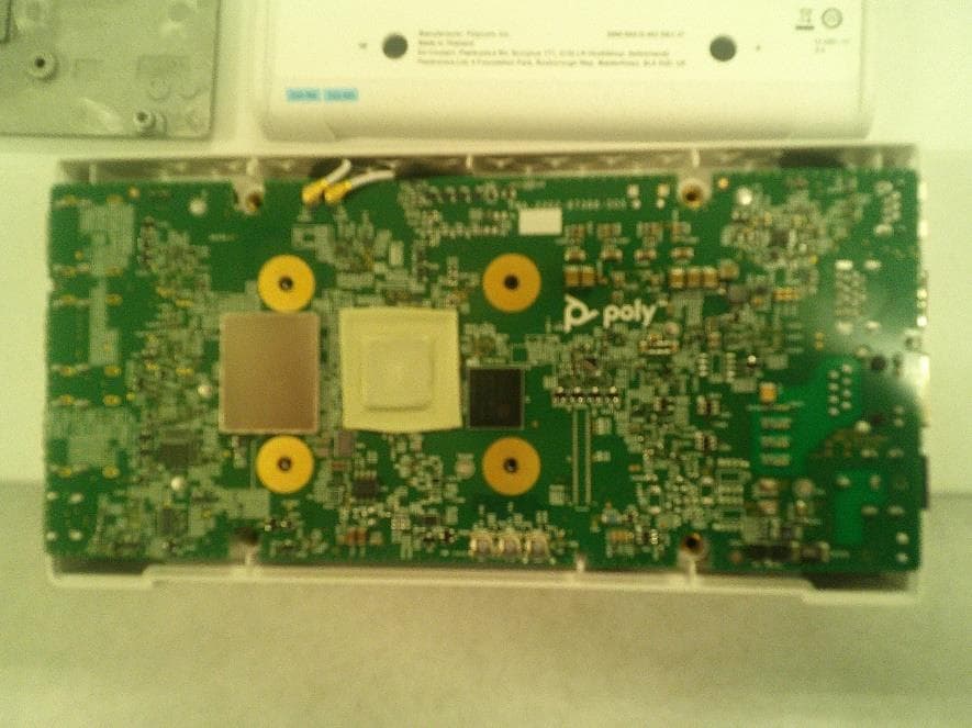
M72-P033
Jan 31, 2023Video CODEC
Equipment Class
DTS - Digital Transmission System