M72-VOICESTConference Phone with Bluetooth Transmitter
HP Inc.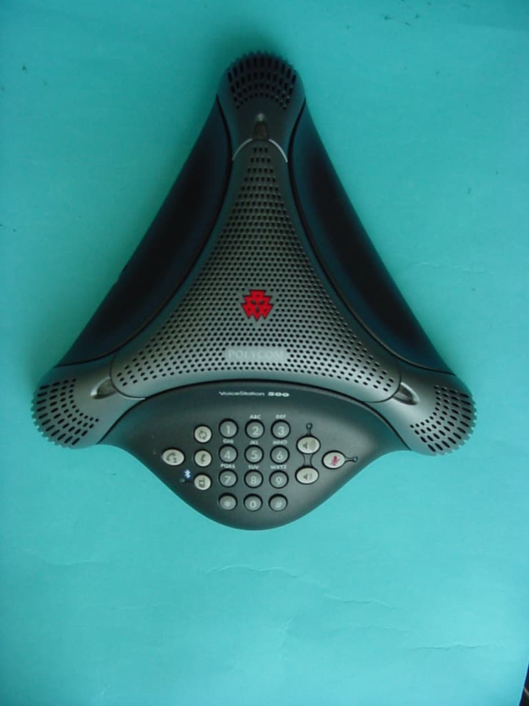
Click to zoom
Application Details
- Equipment Class
- DSS - Part 15 Spread Spectrum Transmitter
- Date of Grant
- Apr 25, 2006
- Application Purpose
- Original Equipment
- Date of Application
- Apr 25, 2006
- Equipment Note
- Conference Phone with Bluetooth Transmitter
- Frequency Range
- 2402.00000000 - 2480.00000000
- Company
- HP Inc.
- Country
- United States
Documents & Files
Document Text
Text extracted from the exhibit documents filed with the FCC. Open a document above to read the original.
Users Manual
USER GUIDE VoiceStation™ 500 User Guide VoiceStation™ 500 - Contents Contents Introduction ...................................................3 Parts List .......................................................3 For Best Performance .......................................3 Installing VoiceStation™ 500 ............................4 Using VoiceStation™ 500 .................................5 Using Bluetooth Audio .....................................8 Maintenance .................................................11 Troubleshooting .............................................11 Polycom Limited Warranty ...............................12 Limitation of Liability .....................................12 Copyright ......................................................13 US and Canada Regulatory and Compliance Information .........................13 Exhibit J - Customer Information ......................15 VoiceStation™ 500 Specifications .....................17 VoiceStation™ 500 - 3 Introduction Parts List Thank you for choosing Polycom’s VoiceStation™ 500. VoiceStation™ 500 uses Polycom’s unique Acoustic Clarity Technology to provide clear, full-duplex, two-way voice communication for your meetings. In addition, VoiceStation™ 500 adapts dynamically to the room environ - ment to eliminate echoes and clipping. Three built-in microphones pick up sound all around the room so you can speak naturally and be easily understood. Please review this User Guide before using the phone. Save this User Guide for future reference. Please take a moment now to complete and mail your VoiceStation™ 500 regis - tration card, or register online at www. polycom.com. Note: Refer to Quick Start Guide for additional information. VoiceStation™ 500 - 4 For Best Performance ► Place VoiceStation™ 500 in the center of a table or desk. ► Locate VoiceStation™ 500 in a room with soft furnishings such as carpets, curtains, and sound-absorbing walls and ceilings. ► Keep papers and other objects away from your VoiceStation™ 500. ► Speak at normal volume. ► Speak toward your VoiceStation™ 500. Installing VoiceStation™ 500 1. Connect one end of the long console cable to the bottom of the phone. 2. Insert the Power Supply plug into a nearby electrical outlet. 3. Connect the other end of the long console cable to the bottom of the Power Supply. VoiceStation™ 500 will run a brief self- test, and then you will hear a tone. If you don’t hear the tone, verify that the outlet is working and the power is switched on. 4. Connect the short telephone cable to the Power Supply. Your System Administrator can help you to identify a standard analog phone line. VoiceStation™ 500 - 5 5. Connect the other end of the short tele- phone cable to a jack wired for a standard analog phone line. ► Do not plug the VoiceStation™ 500 into a digital telephone network. Doing so may damage the phone. 6. Place VoiceStation™ 500 in the center of the room on a flat, stable surface and press the Volume Up and Volume Down buttons to adjust the Ringer. ► The Ringer has three modes: High, Low, and Off. The Ringer sounds when you press the Volume buttons to indicate current status. 7. Press the On/Off button to obtain a dial tone. ► If you do not hear a dial tone, you may not be connected to an analog telephone line. For assistance, contact your System Admin - istrator. ►When the On/Off indicator light is on, the Volume buttons control the sound level of the speaker. ►When the On/Off indicator light is off, the Volume buttons control the ringer volume. Using VoiceStation™ 500 The Polycom ® VoiceStation™ 500 sup- ports three modes of operation: • POTS Audio • Bluetooth Audio (headset and hands- free profile) • 2.5mm Wired Audio The Link Indicator will be slowly flashing blue when the VoiceStation™ 500 is in Bluetooth mode, and it will be solid amber when the phone is in 2.5mm Wired Audio mode (with a cable connected). The Link Indicator is off when the phone is in nor - mal POTS mode. When in POTS mode, inserting a 2.5mm cable automatically enables the Wired Audio mode, and the amber link indicator will automatically come on. It is not pos- sible to have a Bluetooth connection while in the amber mode. Removing the 2.5mm cable automatically reverts the VoiceSta - tion™ 500 to POTS mode. VoiceStation™ 500 - 6 Keypad Dialing a Number Example: POTS Mode Answer a Call Press the button when VoiceStation™ 500 rings. Adjust Speaker Volume When a call is in progress, press the Volume Up or Volume Down button to adjust the sound level. Microphone Mute Press the Mute button to turn off the microphones and prevent the other party from hearing your conversa - tion. The red indicator lights near the microphones will be on. The speaker is still active and you can hear the other party. Press the mute button again to resume two-way communication. The red indicator lights will go out. VoiceStation™ 500 - 7 Pair with Bluetooth Device Press the Link button for 3 seconds to initiate pairing mode. For more information, refer to Using Bluetooth Audio. Special Features Your telephone system may provide special features such as Call Waiting, Conference, or Transfer which can be accessed by pressing the key. Ask your System Administrator for more information on special features available with your phone system. End a Call Press the On/Off button to end the call. Redial Press the Redial button. Record a Conversation Plug the end of a cable with RCA-type connectors into the Aux Out jack on the Power Supply. Plug the other end of the cable into the Aux In jack of your tape recorder. Private Conversations Plug a telephone into the data port on the VoiceSta- tion™ 500 wall module. Press the Hold button to place the call on hold, then pick up the receiver of the telephone connected to the data port. You may also connect a fax machine or computer modem to the data port. Audio cable (RCA cable) VoiceStation™ 500 - 8 Fax Machine Telephone snoitpo trop ataDeludoM llaW Fax Machine Telephone snoitpo trop ataDel…
Text truncated - open the document above for the full version.
External Photos
CETECOM ICT Services GmbH Untertürkheimer Str. 6-10, 66117 Saarbruecken Phone: +49 (0) 681 598-0 Fax: -9075 RSC-Laboratory Phone: +49 (0) 681 598-0 Fax: -9075 Test report no.: 2-4228-01-03/06 Date: 2006-03-14 Page 45 of 57 5 Photographs of EUT Photo 1: CETECOM ICT Services GmbH Untertürkheimer Str. 6-10, 66117 Saarbruecken Phone: +49 (0) 681 598-0 Fax: -9075 RSC-Laboratory Phone: +49 (0) 681 598-0 Fax: -9075 Test report no.: 2-4228-01-03/06 Date: 2006-03-14 Page 46 of 57 Photo 2:
ID Label/Location Info
202NY0624228 R
Internal Photos
CETECOM ICT Services GmbH Untertürkheimer Str. 6-10, 66117 Saarbruecken Phone: +49 (0) 681 598-0 Fax: -9075 RSC-Laboratory Phone: +49 (0) 681 598-0 Fax: -9075 Test report no.: 2-4228-01-03/06 Date: 2006-03-14 Page 48 of 57 Photo 4: CETECOM ICT Services GmbH Untertürkheimer Str. 6-10, 66117 Saarbruecken Phone: +49 (0) 681 598-0 Fax: -9075 RSC-Laboratory Phone: +49 (0) 681 598-0 Fax: -9075 Test report no.: 2-4228-01-03/06 Date: 2006-03-14 Page 49 of 57 Photo 5: CETECOM ICT Services GmbH Untertürkheimer Str. 6-10, 66117 Saarbruecken Phone: +49 (0) 681 598-0 Fax: -9075 RSC-Laboratory Phone: +49 (0) 681 598-0 Fax: -9075 Test report no.: 2-4228-01-03/06 Date: 2006-03-14 Page 50 of 57 Photo 6: CETECOM ICT Services GmbH Untertürkheimer Str. 6-10, 66117 Saarbruecken Phone: +49 (0) 681 598-0 Fax: -9075 RSC-Laboratory Phone: +49 (0) 681 598-0 Fax: -9075 Test report no.: 2-4228-01-03/06 Date: 2006-03-14 Page 51 of 57 Photo 7: CETECOM ICT Services GmbH Untertürkheimer Str. 6-10, 66117 Saarbruecken Phone: +49 (0) 681 598-0 Fax: -9075 RSC-Laboratory Phone: +49 (0) 681 598-0 Fax: -9075 Test report no.: 2-4228-01-03/06 Date: 2006-03-14 Page 52 of 57 Photo 8: CETECOM ICT Services GmbH Untertürkheimer Str. 6-10, 66117 Saarbruecken Phone: +49 (0) 681 598-0 Fax: -9075 RSC-Laboratory Phone: +49 (0) 681 598-0 Fax: -9075 Test report no.: 2-4228-01-03/06 Date: 2006-03-14 Page 53 of 57 Photo 9:
Test Report
CETECOM ICT Services GmbH Untertürkheimer Str. 6-10, 66117 Saarbruecken Phone: +49 (0) 681 598-0 Fax: -9075 RSC-Laboratory Phone: +49 (0) 681 598-0 Fax: -9075 Test report no.: 2-4228-01-03/06 Date: 2006-03-14 Page 1 of 57 P:\06\4228_1\2-4228-01-03_06 VS 500 FCC Rev2.doc Recognized by the Federal Communications Commission Anechoic chamber registration no.: 90462 (FCC) Anechoic chamber registration no.: 3463 (IC) TCB ID: DE 0001 Accredited by the German Accreditation Council DAR–Registration Number DAT-P-176/94-D1 Independent ETSI compliance test house ETSI Accredited Bluetooth ® Test Facility (BQTF) Test report no. : 2-4228-01-03/06 Applicant : Polycom Inc. Type : VoiceStation 500 Test Standard : FCC Part 15.247 RSS-210 Issue 6 FCC ID : M72-VOICEST Certification No. IC : 1849C-VOICEST CETECOM ICT Services GmbH Untertürkheimer Str. 6-10, 66117 Saarbruecken Phone: +49 (0) 681 598-0 Fax: -9075 RSC-Laboratory Phone: +49 (0) 681 598-0 Fax: -9075 Test report no.: 2-4228-01-03/06 Date: 2006-03-14 Page 2 of 57 Table of contents 1. ADMINISTRATIVE DATA ...................................................................................................................................... 3 1.1. ADMINISTRATIVE DATA OF THE TEST FACILITY..................................................................................................... 3 1.1.1 Identification of the testing laboratory ......................................................................................................... 3 1.1.2 Organizational items..................................................................................................................................... 3 1.1.3 Applicant ́s details ........................................................................................................................................ 4 1.2 ADMINISTRATIVE DATA OF MANUFACTURER / MEMBER........................................................................................ 4 1.3 DESCRIPTION OF THE EQUIPMENT UNDER TEST (EUT) .......................................................................................... 5 1.3.1 EUT: Type, S/N etc. ...................................................................................................................................... 5 1.3.2 If RF component testing only, describtion of additional used HW/SW ......................................................... 5 1.3.3 Additional EUT information For IC Canada (appendix 2)...........................................................................6 1.3.4 EUT operating modes ................................................................................................................................... 7 1.3.5 Extreme conditions testing values................................................................................................................. 7 2. TESTSTANDARD & SUMMARY LIST OF ALL PERFORMED TEST CASES .............................................. 8 3. RF MEASUREMENT TESTING ............................................................................................................................. 9 3.1 DESCRIPTION OF TEST SET-UP................................................................................................................................9 3.1.1 Radiated measurements ................................................................................................................................ 9 3.1.2 Conducted measurements ............................................................................................................................. 9 3.2 REFERENCED DOCUMENTS................................................................................................................................... 10 3.3 ADDITIONAL COMMENTS..................................................................................................................................... 10 3.4 ANTENNA GAIN................................................................................................................................................... 10 3.5 CARRIER FREQUENCY SEPARATION §15.247(A1)................................................................................................. 11 3.6 NUMBER OF HOPPING CHANNELS §15.247(A1) .................................................................................................... 12 3.7 TIME OF OCCUPANCY (DWELL TIME) §15.247(A1 III) .......................................................................................... 13 3.8 POWER SPECTRAL DENSITY (HYBRID SYSTEM IN INQUIRY MODE/PAGE SCAN) §15.247(D) ................................. 14 3.9 SPECTRUM BANDWIDTH OF A FHSS SYSTEM / 20DB BANDWITH §15.247(A1) ................................................... 15 3.10 MAXIMUM OUTPUT POWER (CONDUCTED) § 15.247 (B) (1) ................................................................................. 17 3.11 MAX. PEAK OUTPUT POWER (RADIATED) § 15.247 (B) (1).................................................................................... 19 3.12 BAND-EDGE COMPLIANCE OF CONDUCTED EMISSIONS §15.247 (C) ..................................................................... 20 3.13 BAND-EDGE COMPLIANCE OF RADIATED EMISSIONS §15.205 .............................................................................. 23 3.14 SPURIOUS EMISSIONS - CONDUCTED (TRANSMITTER) § 15.247 (C) (1) ............................................................... 26 3.15 SPURIOUS EMISSIONS > 30 MHZ- RADIATED (TRANSMITTER) § 15.247 (C) (1) ................................................... 28 3.16 SPURIOUS EMISSIONS - RADIATED (RECEIVER) § 15.109 ..................................................................................... 35 3.17 SPURIOUS EMISSIONS < 30 MHZ - TRANSMITTER RADIATED § 15.209 ................................................................ 37 3.18 CONDUCTED EMISSIONS <30 MHZ § 15.107/207 ................................................................................................ 38 4 …
Text truncated - open the document above for the full version.
Test Setup Photos
CETECOM ICT Services GmbH Untertürkheimer Str. 6-10, 66117 Saarbruecken Phone: +49 (0) 681 598-0 Fax: -9075 RSC-Laboratory Phone: +49 (0) 681 598-0 Fax: -9075 Test report no.: 2-4228-01-03/06 Date: 2006-03-14 Page 42 of 57 4 Photographs of Test Set-up Photo 1: Radiated Emissions CETECOM ICT Services GmbH Untertürkheimer Str. 6-10, 66117 Saarbruecken Phone: +49 (0) 681 598-0 Fax: -9075 RSC-Laboratory Phone: +49 (0) 681 598-0 Fax: -9075 Test report no.: 2-4228-01-03/06 Date: 2006-03-14 Page 43 of 57 Photo 2: Radiated Emissions CETECOM ICT Services GmbH Untertürkheimer Str. 6-10, 66117 Saarbruecken Phone: +49 (0) 681 598-0 Fax: -9075 RSC-Laboratory Phone: +49 (0) 681 598-0 Fax: -9075 Test report no.: 2-4228-01-03/06 Date: 2006-03-14 Page 44 of 57 Photo 3: Conducted Emissions
Contact Information
Applicant
Richard Tarsio(US/CAN TRSE Worldwide Technical Regulations)
Test Firm
Cetecom ICT Services GmbHRalf Hoehn
Technical Specifications
| # | Rule Parts | Frequency Range | Power Output |
|---|---|---|---|
| 1 | 15C | 2.40 GHz - 2.48 GHz | 1.40 mW |
Other Applications from HP Inc.
M72-EDV250P
Jan 19, 2026Poly Edge V250 Plus
Equipment Class
NII - Unlicensed National Information Infrastructure TXM72-EDV850
Jan 15, 2026Poly Edge V850
Equipment Class
DSS - Part 15 Spread Spectrum TransmitterM72-EDV650
Dec 17, 2025Poly Edge V650
Equipment Class
DTS - Digital Transmission SystemM72-STX72R
Aug 25, 2024Video Bar
Equipment Class
NII - Unlicensed National Information Infrastructure TX
M72-P033
Jan 31, 2023Video CODEC
Equipment Class
DTS - Digital Transmission System