M72BTMOD01Bluetooth Radio Module
HP Inc.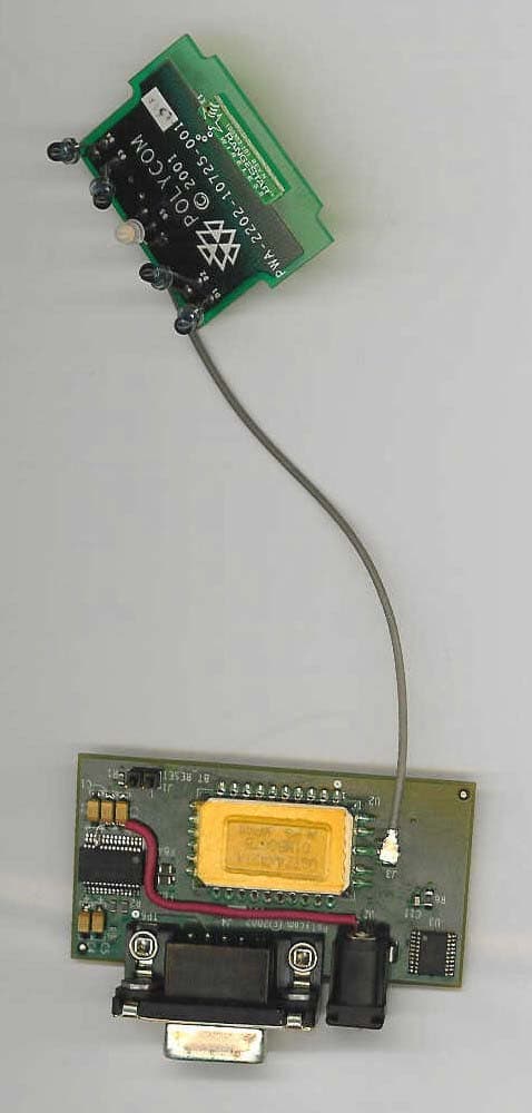
Click to zoom
Application Details
- Equipment Class
- DSS - Part 15 Spread Spectrum Transmitter
- Date of Grant
- Jan 06, 2003
- Application Purpose
- Original Equipment
- Date of Application
- Jan 06, 2003
- Equipment Note
- Bluetooth Radio Module
- Frequency Range
- 2402.00000000 - 2480.00000000
- Company
- HP Inc.
- Country
- United States
Documents & Files
Document Text
Text extracted from the exhibit documents filed with the FCC. Open a document above to read the original.
Users Manual
Polycom Bluetooth Module Integration Note from Corporate compliance to Engineering. The Polycom Bluetooth module is designed to be used in Proprietary Polycom set top videoconferencing products. Usage notes The Module is approved using the FCC ‘unlicensed modular transmitter approval’ method. Therefore the module must only be used with the approved antenna board. Use of another antenna requires re-approval & must be submitted to Polycom corporate compliance for FCC registration. All changes to the module must be made through the Polycom electronic change order process. All Polycom software written to control this device must use the Radio Power Table within the module that controls the maximum output power to +4.16 +/- 2 dBm. When using this module in a Polycom design. The placement of the Antenna and module must meet the following RF exposure requirements. A separation distance of at least 20 cm must be maintained between the antenna of this device and all persons. This Transmitter must not be collocated or operating in conjunction with any other antenna or transmitter. The following labelling & user guide information must be used by anyone using this module. The ECO process will check that these guidelines have been followed. Labelling: The following information must be placed on the Regulatory label of the unit that the module is installed. User Guide: The following statements must be put in the User guide for the product: Item 1 Pt 15 Rules This device complies with part 15 of the FCC Rules. Operation is subject to the following two conditions: (1) This device may not cause harmful interference, and (2) This device must accept any interference received, including interference that may cause undesired operation. Item 2 Class B Digital Device or Peripheral NOTE: The Radio module within this equipment has been tested and found to comply with the limits for a Class B digital device, pursuant to part 15 of the FCC Rules. These limits are designed to provide reasonable protection against harmful interference in a residential installation. This equipment generates, uses and can radiate radio frequency energy and, if not installed and used in accordance with the instructions, may cause harmful interference to radio communications. However, there is no guarantee that interference will not occur in a particular installation. If this equipment does cause harmful interference to radio or television reception, which can be determined by turning the equipment off and on, the user is encouraged to try to correct the interference by one or more of the following measures: • Reorient or relocate the receiving antenna. • Increase the separation between the equipment and receiver. • Connect the equipment into an outlet on a circuit different from that to which the receiver is connected. • Consult the dealer or an experienced radio/TV technician for help. Item 2c RF module included To comply with FCC RF exposure compliance requirements, a separation distance of at least 20 cm must be maintained between the antenna of this device and all persons. This Transmitter must not be collocated or operating in conjunction with any other antenna or transmitter. Item 3 Modifications In accordance with part 15 of the FCC rules, the user is cautioned that any changes or modifications not expressly approved by Polycom Inc. could void the user’s authority to operate the equipment. Note to Integrators: The user guide should NOT provide any instructions on how to remove or install the module.
Cover Letter(s)
January 10, 2003 American Telecommunications Certification Body 6731 Whittier Avenue McLean, VA 22101 Dear Sirs: This letter of attestation is to address the EMC and Outstanding Transmitter Issues address in the December 23, 2002 letter regarding the certification FCC ID: M72BTMOD01. Issue 1 – Polycom waiting on response from ALPS. Issue 2 – Polycom - waiting Issue 3 – Please see amended User Manual Exhibit (6_10_Integration notes_user manual_b.pdf). NOTE – still waiting on Polycom to modify this to satisfy item 7. Issue 4 – Polycom attests that the connector that they use is the Hirose Electric, P/N CL331-0471-0 or U.FL-R-SMT. Hyper attests that the connector on the unit used during the UL tests is this connector (was not an SMA connector, this was in error – see page 27 of the radiated report for photo of the EUT – no SMA connector). The Murata connector reference in the cover letter was an oversight. Issue 5 – Hyper Corporation attests that all configurations meet the required limits. An updated summary has been compiled by Hyper Corporation from the data generated by UL and is attached as Conducted_Summary.pdf in response to the comments / recommendations of the TCB. Issue 6 - Hyper Corporation attests that all of the emissions measured off the device meet the limits described in 15.209. The restricted band requirements of 15.205 (a) are met fulfilling the requirements of 15.247(c), including the restricted band 2483.5 – 2500 GHz beginning at the upper band-edge. No emission measured was over the emission limits in 15.209. Issue 7 – Polycom – will modify integration notes / users manual accordingly. Sincerely, William Elliott Staff Engineer – Wireless Testing Hyper Corporation Phone: 1-925-462-9105 ext. 208 Email: [email protected] 1279 Quarry Lane Pleasanton, California 94566-8499
Cover Letter(s)
1279 Quarry Lane Pleasanton, California 94566-8499 January 8, 2003 American Telecommunications Certification Body 6731 Whittier Avenue McLean, VA 22101 Dear Sirs: This letter of attestation is to address the EMC and Outstanding Transmitter Issues address in the January 7 th , 2003 letter regarding the certification FCC ID: M72BTMOD01. Issue 1 – Please find attached the modified block diagram as requested (7_Block Diagram_c.pdf). Also, please see NOTE regarding updated part number below. Issue 2 – Waiting on drawing Issue 3 – Please see attached file “14.3 Modular Approval Cover Letter_c”. Issue 4 – File sent yesterday from DT Associates (6_10_Integration notes_user manual_c.pdf) included a note to integrators that the end user should not be provided instructions on how to remove or install the device. Is this insufficient? NOTE – On review of the block diagram Polycom has informed us that the ALPS Bluetooth Module Part Number referred to in the operational description and the block diagram has been updated to the ALPS P/N UGTZ4-436A and not the UGTZ4X421A. The only difference between the two parts is software settings in the flash memory. All of the block diagrams and any additional information is correct. Moreover, Polycom attests that all testing was performed with settings for the UGTZ4-436A. Please make note of the updated part number. Sincerely, William Elliott Staff Engineer – Wireless Testing Hyper Corporation Phone: 1-925-462-9105 ext. 208 Email: [email protected]
Cover Letter(s)
American Telecommunications Certification Body Inc. 6731 Whittier Ave, McLean, VA 22101 December 23, 2002 RE: Polycom, Inc. FCC ID: M72BTMOD01 After a review of the submitted information, I have a few comments on the above referenced Application. 1) Please provide a block diagram that shows the frequencies of all the oscillators in the TX portion of the device (CFR 2.1033(a)(5)). 2) Please provide a photograph or drawing show the placement of the label on the device. 3) The users manual mentions setting the maximum output to +6 dBm, while the maximum measured appears to be 4.2 dBm. Please comment. Note that all exhibits are expected to consistent. 4) The modular approval letter states the antenna connector is a Murata Connector, the schematics state a Hirose connector, and the UL report states a SMA connector. Please comment. 5) Page 15 of 49 of the UL test report states that the data in the summary is the worse case ("highest") data shown. Data plots show higher data measured (although margin may be more because of comparing against 2 separate limits and not just the average limit). Not all data plots were provided for all configurations. Please confirm that all configurations meet the limits and adjust the summary to appropriately shows "highest" data measured. 6) The Addendum to the radiated test report discusses bandedge compliance for 20 dB below the fundamental. However, how about restricted band limits at the bandedge? 7) The users manual should include an explanation to the OEM integrator that the end user should NOT be provided any instructions on how to remove or install the device. 8) FYI.....Grant Conditions: Modular Approval. Power Output listed is conducted. Approval is limited to OEM installation only. The antenna(s) used for this transmitter must be installed to provide a separation distance of at least 20 cm from all persons and must not be co-located or operating in conjunction with any other antenna or transmitter. OEM integrators must be provided with antenna installation instructions. OEM integrators and end-Users must be provided with transmitter operation conditions for satisfying RF exposure compliance. This grant is valid only when the device is sold to OEM integrators and the OEM integrators are instructed to ensure that the end user has no manual instructions to remove or install the device. Timothy R. Johnson Examining Engineer mailto: [email protected] The items indicated above must be submitted before processing can continue on the above referenced application. Failure to provide the requested information may result in application termination. Correspondence should be considered part of the permanent submission and may be viewed from the Internet after a Grant of Equipment Authorization is issued. Please do not respond to this correspondence using the email reply button. In order for your response to be processed expeditiously, you must submit your documents through the AmericanTCB.com website. Also, please note that partial responses increase processing time and should not be submitted. Any questions about the content of this correspondence should be directed to the sender.
Cover Letter(s)
American Telecommunications Certification Body Inc. 6731 Whittier Ave, McLean, VA 22101 January 7, 2003 RE: Polycom, Inc. FCC ID: M72BTMOD01 After a review of the submitted information, I have a few comments on the above referenced Application. 1) Please provide a block diagram that shows the frequencies of all the oscillators in the TX portion of the device (CFR 2.1033(a)(5)). 2) Please provide a photograph or drawing show the placement of the label on the device. 3) Please adjust the modular approval letter to reference the correct antenna connector. 4) The users manual should include an explanation to the OEM integrator that the end user should NOT be provided any instructions on how to remove or install the device. Timothy R. Johnson Examining Engineer mailto: [email protected] The items indicated above must be submitted before processing can continue on the above referenced application. Failure to provide the requested information may result in application termination. Correspondence should be considered part of the permanent submission and may be viewed from the Internet after a Grant of Equipment Authorization is issued. Please do not respond to this correspondence using the email reply button. In order for your response to be processed expeditiously, you must submit your documents through the AmericanTCB.com website. Also, please note that partial responses increase processing time and should not be submitted. Any questions about the content of this correspondence should be directed to the sender.
Cover Letter(s)
PART 15 UNLICENSED MODULAR TRANSMITTER APPROVAL Cover Letter and Response Addressing FCC Public Notice DA 00-1407 Polycom Inc. Wish to apply for a modular transmitter approval for our Bluetooth Module, BTMOD01. The Module is designed to be used Only in Proprietary Polycom set top videoconferencing products. The Polycom Procedure, ‘PRODUCT AND DOCUMENT CHANGE’ Document Number 3833-00001-002, will control its use & any changes to it. The Corporate Compliance group of Polycom have Written the document ‘Polycom Bluetooth Module Integration notes’ Which gives information to the engineering groups who will incorporate this module into their designs. The following statements support this application: 1. The modular transmitter has its own RF shielding. 2. The modular transmitter has a 2K Uart buffered data input 3. The modular transmitter has its own power supply regulation 4. The modular transmitter complies with the antenna requirements of Section 15.203 and 15.204 and uses a “unique” (Hirose Electric, P/N CL331-0471-0 or U.FL-R-SMT) connector at the antenna and the module connection. Any antenna used with the module will be the one approved with the module or will be approved through a Class II permissive change. 5. The module was tested in stand-alone configuration with typical length cables. No ferrites were used and no accessories, peripherals, or support equipment were required for testing. 6. This appropriate labeling will be applied to the device. 7. The unit complies with the requirements found in 15.247. 8. The module has a maximum output power of +4.16 dBm +/- 2 dB and will only be used in mobile devices primarily business equipment (e.g. videoconferencing equipment).
ID Label/Location Info
Polycom Bluetooth Module Labeling Description The module will have will have a label permanently attached to the PCB. Material: Matte Metallized Tamper- Evident Polyester (B-438) Label Size - W X H: 16.51 mm x 5.08 mm (0.65 in x 0.20 in ). The label shall appear as indicated below: FCC ID: M72BTMOD01 IC: 1849D-BTMOD01
Operational Description
BLUETOOTH APPROVALS The following exhibit indicates the FCC Spread Spectrum requirements in Section 15.247 for devices meeting the Bluetooth Specifications in the 2.4 GHz band as of February 2001 operating in the USA. The purpose of this exhibit is to help expedite the approval process for Bluetooth devices. This exhibit provides items that vary for each device and also provides a list of items that are common to Bluetooth devices that explains the remaining requirements. The list of common items can be submitted for each application for equipment authorization. This exhibit only specifies requirements in Section 15.247, requirements in other rule Sections for intentional radiators such as in Section 15.203 or 15.207 must be also be addressed. For each individual device, the following items, 1-7 will vary from one device to another and must be submitted. 1) The occupied bandwidth in Section 15.247(a)(1)(ii). 2) Conducted output power specified in Section 15.247(b)(1). 3) EIRP limit in Section 15.247(b)(3). 4) RF safety requirement in Section 15.247(b)(4) 5) Spurious emission limits in Section 15.247©. 6) Processing gain and requirements for Hybrids in Section 15.247(f) in the acquisition mode. 7) Power spectral density requirement in Section 15.247(f) in the acquisition mode. For all devices, the following items, 1-12, are common to all Bluetooth devices and will not vary from one device to another. This list can be copied into the filing. 1 Output power and channel separation of a Bluetooth device in the different operating modes: The different operating modes (data-mode, acquisition-mode) of a Bluetooth device don’t influence the output power and the channel spacing. There is only one transmitter which is driven by identical input parameters concerning these two parameters. Only a different hopping sequence will be used. For this reason, the RF parameters in one op-mode is sufficient. 2 Frequency range of a Bluetooth device: The maximum frequency of the device is: 2402 – 2480 MHz. This is according the Bluetooth Core Specification V 1.0B (+ critical errata) for devices which will be operated in the USA. Other frequency ranges ( e.g. for Spain, France, Japan) which are allowed according the Core Specification must not be supported by the device. 3 Co-ordination of the hopping sequence in data mode to avoid simultaneous occupancy by multiple transmitters: Bluetooth units which want to communicate with other units must be organized in a structure called piconet. This piconet consist of max. 8 Bluetooth units. One unit is the master the other seven are the slaves. The master co-ordinates frequency occupation in this piconet for all units. As the master hop sequence is derived from it’s BD address which is unique for every Bluetooth device, additional masters intending to establish new piconets will always use different hop sequences. 4 Example of a hopping sequence in data mode: Example of a 79 hopping sequence in data mode: 40, 21, 44, 23, 42, 53, 46, 55, 48, 33, 52, 35, 50, 65, 54, 67, 56, 37, 60, 39, 58, 69, 62, 71, 64, 25, 68, 27, 66, 57, 70, 59, 72, 29, 76, 31, 74, 61, 78, 63, 01, 41, 05, 43, 03, 73, 07, 75, 09, 45, 13, 47, 11, 77, 15, 00, 64, 49, 66, 53, 68, 02, 70, 06, 01, 51, 03, 55, 05, 04 5 Equally average use of frequencies in data mode and short transmissions: The generation of the hopping sequence in connection mode depends essentially on two input values: 1. LAP/UAP of the master of the connection 2. Internal master clock The LAP (lower address part) are the 24 LSB’s of the 48 BD_ADDRESS. The BD_ADDRESS is an unambiguous number of every Bluetooth unit. The UAP (upper address part) are the 24 MSB’s of the 48 BD_ADDRESS. The internal clock of a Bluetooth unit is derived from a free running clock which is never adjusted and is never turned off. For synchronization with other units, only the offsets are used. It has no relation to the time of the day. Its resolution is at least half the RX/TX slot length of 312.5 μs. The clock has a cycle of about one day (23h30). In most case it is implemented as 28 bit counter. For the deriving of the hopping sequence the entire LAP (24 bits), 4 LSB’s (4 bits) (Input 1) and the 27 MSB’s of the clock (Input 2) are used. With this input values different mathematical procedures (permutations, additions, XOR-operations) are performed to generate the sequence. This will be done at the beginning of every new transmission. Regarding short transmissions, the Bluetooth system has the following behavior: The first connection between the two devices is established, a hopping sequence is generated. For transmitting the wanted data, the complete hopping sequence is not used and the connection ends. The second connection will be established. A new hopping sequence is generated. Due to the fact that the Bluetooth clock has a different value, because the period between the two transmission is longer (and it cannot be shorter) than the minimum resolution of the clock (312.5 μs). The hopping sequence will always differ from the first one. 6 Receiver input bandwidth, synchronization and repeated single or multiple packets: The input bandwidth of the receiver is 1 MHz. In every connection, one Bluetooth device is the master and the other one is the slave. The master determines the hopping sequence (see chapter 5). The slave follows this sequence. Both devices shift between RX and TX time slot according to the clock of the master. Additionally the type of connection (e.g. single or multi-slot packet) is set up at the beginning of the connection. The master adapts its hopping frequency and its TX/RX timing is according to the packet type of the connection. Also, the slave of the connection uses these settings. Repeating of a packet has no influence on the hopping sequence. The hopping sequence generated by the master of the connection will be followed in any case. That means, a repeated packet will not be send on the same frequency, it is send on the next frequency …
Text truncated - open the document above for the full version.
RF Exposure Info
MPE Safe Distance Calculation Hyper Corp. Report No: 703-0207005-BTMOD Date November 17, 2002 Rev 001 “Wireless that Works” SM 1279 Quarry Lane • Suite B, Pleasanton, CA 94566-8499 USA Phone: +1.925.462.9105 Fax: +1.925.280.7751 MPE Safe Distance Calculation Report No.: 703-0207005-BTMOD Product Name: Polycom Bluetooth Radio Module Issued Date: November 17, 2002 Applicant: Polycom ® , Inc. 78A Monnow Street Monmouth NP25 3EQ United Kingdom Phone: +44 (0) 1600-716950 Fax: +44 (0) 1600-715799 Bluetooth is a Trademark owned by Bluetooth SIG, Inc. and licensed to Hyper Corp. Hyper Corp is a BLUETOOTH Qualification Test Facility (BQTF) for RF Conformance Testing and an Associate Member of the SIG Certificate Number 1708-1 Hyper Corp is an Accredited Laboratory by The American Association For Laboratory Accreditation (A2LA) to ISO/IEC 17025-for the scope of BLUETOOTH Testing. QCD0004 Page 1 of 8 MPE Safe Distance Calculation Hyper Corp. Report No: 703-0207005-BTMOD Date November 17, 2002 Rev 001 This document may not be reproduced without written consent from Hyper Corporation. Extracts are never permitted. After written consent from Hyper Corporation, the document must be reproduced in its entirety. Bluetooth is a Trademark owned by Bluetooth SIG, Inc. and licensed to Hyper Corp. Hyper Corp is a BLUETOOTH Qualification Test Facility (BQTF) for RF Conformance Testing and an Associate Member of the SIG Certificate Number 1708-1 Hyper Corp is an Accredited Laboratory by The American Association For Laboratory Accreditation (A2LA) to ISO/IEC 17025-for the scope of BLUETOOTH Testing. QCD0004 Page 2 of 8 MPE Safe Distance Calculation Hyper Corp. Report No: 703-0207005-BTMOD Date November 17, 2002 Rev 001 Signature Page The below listed Hyper Corporation Personnel takes responsibility for the contents of this Test Report. Signatures Test Engineer(s): Original signed William Elliott 11.17.02 Date Reviewed by Technical Manager: Original signed Kevin Marquess 11.17.02 Date Bluetooth is a Trademark owned by Bluetooth SIG, Inc. and licensed to Hyper Corp. Certificate Number 1708-1 Hyper Corp is a BLUETOOTH Qualification Test Facility (BQTF) for RF Conformance Testing and an Associate Member of the SIG Hyper Corp is an Accredited Laboratory by The American Association For Laboratory Accreditation (A2LA) to ISO/IEC 17025-for the scope of BLUETOOTH Testing. QCD0004 Page 3 of 8 MPE Safe Distance Calculation Hyper Corp. Report No: 703-0207005-BTMOD Date November 17, 2002 Rev 001 1. List of Revisions Version Date Author(s) Description 001 November 17, 2002 William Elliott Initial Version Bluetooth is a Trademark owned by Bluetooth SIG, Inc. and licensed to Hyper Corp. Certificate Number 1708-1 Hyper Corp is a BLUETOOTH Qualification Test Facility (BQTF) for RF Conformance Testing and an Associate Member of the SIG Hyper Corp is an Accredited Laboratory by The American Association For Laboratory Accreditation (A2LA) to ISO/IEC 17025-for the scope of BLUETOOTH Testing. QCD0004 Page 4 of 8 MPE Safe Distance Calculation Hyper Corp. Report No: 703-0207005-BTMOD Date November 17, 2002 Rev 001 TABLE OF CONTENTS 1. List of Revisions.............................................................................................4 2. Disclaimer Notice...........................................................................................5 3. Reproduction Clause.....................................................................................5 4. General Information.......................................................................................6 4.1 I DENTIFICATION OF THE EUT....................................................................6 4.2 ANTENNA DESCRIPTION...........................................................................6 4.3 M AXIMUM PERMISSIBLE EXPOSURE..........................................................7 4.3.1 Calculations......................................................................................................7 4.3.2 Results.............................................................................................................8 2. Disclaimer Notice This test report applies only to the EUT (Equipment Under Test) and the results of the specifications called out in this report. The test results contained herein relate only to the model(s) identified. It is the manufacturer’s responsibility to assure that additional production units of this model are manufactured with identical electrical and mechanical characteristics. This Report must not be used to claim product endorsement by A2LA or any agency of the U.S. Government. 3. Reproduction Clause This document may not be reproduced without written consent from Hyper Corporation. Extracts are never permitted. After written consent from Hyper Corporation, the document must be reproduced in its entirety. Bluetooth is a Trademark owned by Bluetooth SIG, Inc. and licensed to Hyper Corp. Certificate Number 1708-1 Hyper Corp is a BLUETOOTH Qualification Test Facility (BQTF) for RF Conformance Testing and an Associate Member of the SIG Hyper Corp is an Accredited Laboratory by The American Association For Laboratory Accreditation (A2LA) to ISO/IEC 17025-for the scope of BLUETOOTH Testing. QCD0004 Page 5 of 8 MPE Safe Distance Calculation Hyper Corp. Report No: 703-0207005-BTMOD Date November 17, 2002 Rev 001 4. General Information 4.1 Identification of the EUT Manufacturer: Polycom ® Inc. Model No.: Polycom Bluetooth Radio Module Hardware Version: Rev 1.0 Software Version: Rev 1.0 FCC ID: M72BTMOD01 Frequency Range: 2402 MHz ~ 2480 MHz Channel Number: 79 Frequency of Each Channel: 2402 + k (MHz), k=0~78 Type of Modulation: GFSK Manufacturer Specified Max. Power Output: +4.16 dBm Sample Received Date: September 20, 2002 Test Dates: November 14, 2002 – November 17, 2002 Test Facility: Hyper Corporation 1279 Quarry Lane, Suite B Pleasanton, CA 94566, USA 4.2 Antenna Description Antenna Gain: Peak Gain: 0 dBi Rangestar Wireless Bluet…
Text truncated - open the document above for the full version.
Test Report
1279 Quarry Lane Pleasanton, California 94566-8499 January 6, 2003 American Telecommunications Certification Body 6731 Whittier Avenue McLean, VA 22101 Dear Sirs: Please find attached below a new summary compilation of the highest line conducted spurious emissions in response to Issue 5 on the ATCB comments to the certification submission for FCC ID: M72BTMOD01. Hyper attests that all configurations meet the limits. In addition, the summary tables in the report from UL inadvertently state that the data reported was high channel data while the raw data states middle channel data. Hyper Corporation attests that all data reported is from the middle channel. The statement about high channel data in the summaries appears to be an administrative oversight. The following table reports the highest emissions measured from the device. The data from the original table is included as well as the worst case peak measurements from page 18 of the data. This is the data that the included plot showing peak values over the average limit. Peak values are compared to the QP limit and average values are compared to the average limit. Summary of Reported Line Conducted Data Frequency (MHz) Peak CORR'D (dBuV) Average CORR'D (dBuV) Site CF QP Limit (dBuV) Avg Limit (dBuV) Margin to Limit Notes Raw Data 0.15745 50.63 -------- 6 65.6 -------- -14.97 Line 2 p 20 0.1835 46.98 -------- 6 64.3 -------- -17.32 Line 2 p 20 0.41429 51.33 -------- 6 57.6 -------- -6.27 Line 1 p 18 0.41429 -------- 30.96 6 -------- 47.6 -16.64 Line 1 p 17 0.58552 49.22 -------- 6 56 -------- -6.78 Line 1 p 18 0.58552 -------- 28.05 6 -------- 47 -17.95 Line 1 p 17 0.79398 48.75 -------- 6 56 -------- -7.25 Line 1 p 18 0.79398 -------- 25.1 6 -------- 46 -20.9 Line 1 p 17 1.13644 46.9 -------- 6 56 -------- -9.1 Line 1 p 18 1.13644 -------- 25.01 6 -------- 46 -20.99 Line 1 p 17 1.56824 46.83 -------- 6 56 -------- -9.17 Line 1 p 18 1.56824 -------- 23.91 6 -------- 46 -20.99 Line 1 p 17 0.60413 31.27 -------- 6 56 -------- -24.73 Line 2 p 20 18.56848 39.3 -------- 6 60 -------- -20.7 Line 2 p 20 January 6, 2003 Sincerely, William Elliott Staff Engineer – Wireless Testing Hyper Corporation Phone: 1-925-462-9105 ext. 208 Email: [email protected]
Test Report
1279 Quarry Lane Pleasanton, California 94566-8499 December 31, 2002 American Telecommunications Certification Body 6731 Whittier Avenue McLean, VA 22101 Dear Sirs: Please find attached below a summary compilation of the highest radiated spurious emissions in response to Issue 5 on the ATCB comments to the certification submission for FCC ID: M72BTMOD01. Hyper Corporation attests that the transmitter testing that was performed at the low, middle, and high channels for testing emissions from the device. Emissions were maximized at each channel following the procedures in ANSI C63.4. In addition, Hyper attests that all configurations meet the limits. The following table reports the highest emissions measured from the device. Radiated Emission Summary (Highest Reported Emissions) for FCC ID: M72BTMOD01 Frequency (MHz) Channel Peak (dBuV) Average (dBuV) Site CF Peak CORR'D (dBuV/m) Average CORR'D (dBuV/m) Limit 15.209 Margin to Limit 4803.9 Low 51 35 4.3 55.3 39.3 54 -14.7 4881.6 Mid 48 34 4.5 52.5 38.5 54 -15.5 4960 High 51.4 -------- 4.7 51.4 -------- 54 -2.6 4803.7 Low 48.1 -------- 4.3 48.1 -------- 54 -5.9 2344.4 Low 47.5 -------- -1.8 47.5 -------- 54 -6.5 2418.09 Low 45.8 -------- -1.5 45.8 -------- 54 -8.2 Sincerely, William Elliott Staff Engineer – Wireless Testing Hyper Corporation Phone: 1-925-462-9105 ext. 208 Email: [email protected]
Test Report
PROJECT #: 02SC14379 Underwriters Laboratories IncA not-for-profit organization dedicated 1655 Scott Blvd Page 1 of 49 to public safety and committed to Santa Clara CA 95050-4169quality service for over 100 years. EMC Services Department Tel: (408) 985-2400 x32397 Fax: (408) 556-6071 FCC CLASS B (CFR 47, Part 15, Subpart B) COMPLIANCE TEST REPORTS for Electromagnetic Emissions of POLYCOM BLUETOOTH RADIO MODULE Model Number: None Serial Number: 00:07:86:00:27:30 Test Standards: CFR 47, Part 15, Subpart B-1998 (ANSI C63.4-1992), Spurious Emissions Prepared for: HYPER CORPORATION 1279 Quarry Lane, Suite B Pleasanton, CA 94566 Prepared by: Underwriters Laboratories, Incorporated 11825 Niles Canyon Road Sunol, CA 94586 (925) 862-9051 REPORT DATE: NOVEMBER 19, 2002 PROJECT #: 02SC1…
Text truncated - open the document above for the full version.
Contact Information
Applicant
Yuk Wan(Director Product Compliance)
Technical Contact
Hyper CorporationDennis Ward
[email protected]209-966-2145
1279 Quarry Lane, Suite B · Pleasanton, California · United States
Non-Technical Contact
Hyper CorporationDennis Ward
[email protected]209-966-2145
Test Firm
Underwriters Laboratories Inc.Mike Willie
Technical Specifications
| # | Rule Parts | Frequency Range | Power Output |
|---|---|---|---|
| 1 | 15C | 2.40 GHz - 2.48 GHz | 2.60 mW |
Other Applications from HP Inc.
M72-EDV250P
Jan 19, 2026Poly Edge V250 Plus
Equipment Class
NII - Unlicensed National Information Infrastructure TXM72-EDV850
Jan 15, 2026Poly Edge V850
Equipment Class
DSS - Part 15 Spread Spectrum TransmitterM72-EDV650
Dec 17, 2025Poly Edge V650
Equipment Class
DTS - Digital Transmission SystemM72-STX72R
Aug 25, 2024Video Bar
Equipment Class
NII - Unlicensed National Information Infrastructure TX
M72-P033
Jan 31, 2023Video CODEC
Equipment Class
DTS - Digital Transmission System