M8D62372311Density Meter
Toshiba Corporation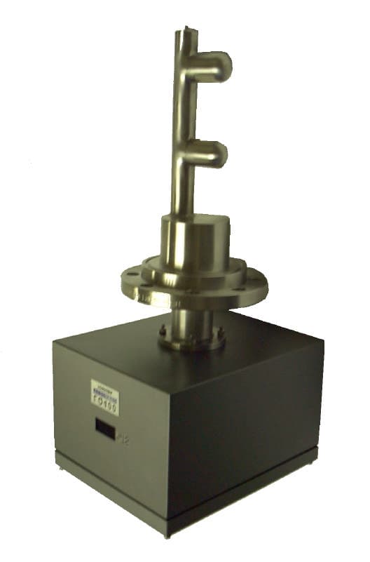
Click to zoom
Application Details
- Equipment Class
- DXT - Part 15 Low Power Transceiver, Rx Verified
- Date of Grant
- Mar 14, 2002
- Application Purpose
- Original Equipment
- Date of Application
- Mar 14, 2002
- Equipment Note
- Density Meter
- Frequency Range
- 1825.00000000 - 1975.00000000
- Company
- Toshiba Corporation
- Country
- Japan
Documents & Files
Document Text
Text extracted from the exhibit documents filed with the FCC. Open a document above to read the original.
Users Manual
6 F 8 A 0 7 8 7 Operation Manual For The Insertion Type Density Meter Type LQ300A00****** © TOSHIBA Corporation 2002 All Rights Reserved. 1 6 F 8 A 0 7 8 7 Notice 1. Do not copy or transcribe this manual in part or entirety without written permission from Toshiba. 2. The manual is subject to change without notice. 3. Although we tried hard to make this manual error free, if you find any errors or unclear passages, kindly let us know. 2 6 F 8 A 0 7 8 7 INTRODUCTION Thank you very much for your purchase of the LQ300A00****** Density Meter. This manual is prepared for people in charge of installation, operation or maintenance. The manual describes the precautions in using the meter, and explains about installing, adjusting, calibrating and maintaining the LQ300A00****** meter. Carefully read this manual before using the meter for efficient and safe operation. Always keep the manual in a place where you can easily access. About Safety Precautions Carefully read the Safety Precautions that appear in the following pages before using the Meter. The safety signs used in the Safety Precautions will appear again in the following sections for your safety. 3 6 F 8 A 0 7 8 7 Safety Precautions Important information is shown on the product itself and in the operation manual to protect users from bodily injuries and property damages, and to enable them to use the product safely and correctly. Please be sure to thoroughly understand the meanings of the following signs and symbols before reading the sections that follow, and observe the instructions given herein. Keep the manual in a place you can easily access to whenever you need it. [ Explanation of Signs] SignDescription WARNING Indicates a potentially hazardous situation which could result in death or serious injury, if you do not follow the instructions in this manual. CAUTION Indicates a potentially hazardous situation which may result in minor or moderate injury, and/or equipment-only-damage, if you do not follow the instruction in this manual. Note 1:Serious injury refers to cases of loss of eyesight, wounds, burns (high or low temperature), electric shock, broken bones, poisoning, etc., which leave after-effects or which require hospitalization or a long period of outpatient treatment of cure. Note 2:Minor or moderate injury refers to cases of burns, electric shock, etc., which do not require hospitalization or a long period of outpatient treatment for cure; equipment damage refers to cases of extensive damage involving damage to property or equipment. [ Explanation of the Symbols] SymbolDescription This sign indicates PROHIBITION (Do not). The content of prohibition is shown by a picture or words beside the symbol. This sign indicates MANDATORY ACTION (You are required to do). The content of action is shown by a picture or words beside the symbol. This shape or symbol indicates WARNING. The content of WARNING is shown by a picture or words beside the symbol. Color back : red, flame, picture and words : black This shape or symbol indicates CAUTION. The content of CAUTION is shown by a picture or words beside the symbol. Color back : yellow, flame, picture and words : black Red Yellow Red Yellow 4 6 F 8 A 0 7 8 7 Safety Precautions (Continued) For a safe use of the LQ300A00****** Density Meter, take precautions described in this manual and observe ordinances in making the installation and operation. Toshiba is not responsible for any accident arising from the use that does not conform to above. INSTALLATION PRECAUTIONS WARNING DO The meter is heavy. To move them or relocate them may need a qualified operator for handling a crane, a hoist or a truck for safe operation. DO Electrical and mechanical constructions are necessary for the meter. Please consult your vender or Toshiba sales representative. Inadequate construction can cause electric shock and fire. DO When hoisting this unit, use the hoisting bands. In addition, when hoisting the unit with hoisting bands, tighten the bands so that the bands will not be loosened or slipped off. Overturning or dropping can cause injuries or equipment failure. DON’T Do not operate where there is a possibility of leakage of flammable or explosive gas. A fire or explosion can occur. CAUTION DO Avoid installing the meter in any of the following places: lDusty place lPlace where corrosive gases (SO2, H2S) or flammable gases may be generated. lPlace exposed to vibration or shock that exceeds permissible level. lPlace exposed to condensation due to abrupt change in temperature. lPlace too cold or hot for installation lPlace too humid for installation lNear an apparatus that generates strong radio waves or strong magnetic field. Otherwise, a fire or equipment breakdown or failure can occur. DO Install the meter in a place that is good for operation, maintenance and inspection. A stumble or an overturn can cause injuries. Yellow Red 5 6 F 8 A 0 7 8 7 Safety Precautions (Continued) WIRING PRECAUTIONS WARNING DO Be sure to install a fuse and a switch to disconnect the equipment from the power source. Failure to observe this can cause electric shock or equipment failure. DO Be sure to ground the equipment using a grounding wire separate from those used for power tools. (With 100 Ohms or less ground resistance) Without grounding, electric shock, malfunction, or equipment failure can be caused by electric leakage. DO Make sure that the main power line is off before wiring or cabling. Wiring or cabling without switching off the main power line can cause electric shock. DO Use crimp terminals with insulation sleeves for power line and grounding wire terminals. A disconnected cable or wire from the terminal or a loose terminal can cause electric shock or generate heat and cause a fire or equipment failure. DO Wiring and cabling should be done as shown in the wiring and connection diagrams. Wrong wiring or cabling can cause malfunctions, overheating, sparking, or electric shock. DON’T Do not wire or cable…
Text truncated - open the document above for the full version.
Cover Letter(s)
From: Kyozo Ouchi [[email protected]] Sent: Thursday, March 14, 2002 11:02 PM To: [email protected] Subject: RE:FW: Toshiba Corporation, FCC ID:M8D62372 TO: mike Kuo From: Kyozo Ouchi Date: Mar/15/2002 I will inform you as below; Answer for Q#1: Setup photos submit by e-filing as Exhibit k-1. Answer for Q#2: Emissions below 1GHz are emitting constantly even if non-transmitting condition. Accordingly it seems that 15.209(a) is not applicable. 15.109(a) in Unintentional Radiators will be applied. Therefore, it complies with 15.209(c), we believe. Please let us have your comments. Answer for Q#3: EUT External Photo submit by e-filing as Exhibit K-2. Regards, Kyozo Ouchi
External Photos
FCC Label Converter Rating Label FCC ID:M8D62372311
Internal Photos
FCC ID:M8D62372311FCC ID:M8D62372311 FCC ID:M8D62372311 FCC ID:M8D62372311 FCC ID:M8D62372311 FCC ID:M8D62372311FCC ID:M8D62372311 FCC ID:M8D62372311 FCC ID:M8D62372311 FCC ID:M8D62372311 FCC ID:M8D62372311 FCC ID:M8D62372311 FCC ID:M8D62372311 FCC ID:M8D62372311 FCC ID:M8D62372311 FCC ID:M8D62372311 FCC ID:M8D62372311
Test Report
JAPAN QUALITY ASSURANCE ORGANIZATION 21-25, KINUTA 1-CHOME, SETAGAYA-KU, TOKYO 157-8573 JAPAN PHONE (03) 3416-0111, TELEX 242-2531 JQA J FAX (03) 3416-9691 JQA APPLICATION NO.: 400-10722 Issue Date : March 6, 2002 Page 1 of 42 EMI TEST REPORT JQA APPLICATION NO. : 400-10722 Model No. : LQ300A00 Type of Equipment : Insertion Type Density Meter Regulations Applied : CFR 47 FCC Rules and Regulations Part 15 FCC ID : M8D62372311 Applicant : Toshiba Corporation Social Infrastructure Systems Company Address : 1, Toshiba-cho, Fuchu-shi, Tokyo 183-8511, Japan Manufacture : Toshiba Corporation Social Infrastructure Systems Company Address : 1, Toshiba-cho, Fuchu-shi, Tokyo 183-8511, Japan Received date of EUT : February 4, 2002 Final Judgment : Passed Test results in this report are obtained in use of equipment that is traceable to National Institute of Advanced Industrial Science and Technology (AIST) of Japan and Communication Research Laboratory (CRL) of Japan. The test results only respond to the tested sample. This report should not be reproduced except in full, without the written approval of JQA EMC Engineering Dept. Testing Div. C O P Y JQA Application No. :400-10722 FCC ID :M8D62372311 Model No. :LQ300A00 Issue Date :March 6, 2002 Standard :CFR 47 FCC Rules Part 15 Page 2 of 42 JAPAN QUALITY ASSURANCE ORGANIZATION TABLE OF CONTENTS Page 1 Documentation 1.1 Test Regulation 3 1.2 General Information 3 1.3 Test Condition 4 – 8 1.4 EUT Modifications / Deviation from Standard 9 1.5 Test results 10 1.6 Summary 11 1.7 Test Configuration / Operation of EUT 12 1.8 EUT Arrangement(Drawing) 13 1.9 Preliminary Test and Test-setup (Drawings) 14 – 19 1.10 EUT Arrangement (Photographs) 20 - 21 2 Test Data 2.1 AC Power Line Conducted Emission 0.45 MHz – 30 MHz 22 - 23 2.2 Radiated Emission (Electric Field) 24 – 35 2.3 Frequency Stability N/A 2.4 Occupied Bandwidth 36 – 42 C O P Y JQA Application No. :400-10722 FCC ID :M8D62372311 Model No. :LQ300A00 Issue Date :March 6, 2002 Standard :CFR 47 FCC Rules Part 15 Page 3 of 42 JAPAN QUALITY ASSURANCE ORGANIZATION 1 DOCUMENTATION 1.1 TEST REGULATION FCC Rules and Regulations Part 15 Subpart A and C (June 23, 1989) Intentional Radiators Test procedure : AC power line conducted emission, radiated emission, frequency stability and occupied bandwidth tests were performed according to the procedures in ANSI C63.4-1992. 1.2 GENERAL INFORMATION 1.2.1 Test facility : 1) Test Facility located at EMC Engineering Dept. Testing Div. : - No.2 and 3 Anechoic Chambers( 3 meters Site ). - Shielded Enclosure. Expiration date of FCC test facility filing : June 04, 2002 2) EMC Engineering Dept. Testing Div. is recognized under the National Voluntary Laboratory accreditation Program for satisfactory compliance established in title 15, Part 285 Code of Federal Regulations. NVLAP Lab Code : 200189-0 (Effective through : June 30, 2002) 1.2.2 Description of the Equipment Under Test (EUT) : 1) Type of Equipment : Insertion Type Density Meter 2) Product Type : Prototype 3) Category : Low Power Transceiver, Rx Verified 4) EUT Authorization : Certification 5) FCC ID : M8D62372311 6) Trade Name : LQ300A00 7) Model No. : LQ300A00 8) Operating Frequency Range : 1825 MHz - 1975 MHz 9) Highest Frequency Used in the EUT : 1975 MHz 10) Serial No. : - 11) Date of Manufacture : - 12) Power Rating : 120 VAC, 60 Hz 13) EUT Grounding : Grounded at the plug end of the power line cord 1.2.3 Definitions for symbols used in this test report : x - indicates that the listed condition, standard or equipment is applicable for this report. - indicates that the listed condition, standard or equipment is not applicable for this report. C O P Y JQA Application No. :400-10722 FCC ID :M8D62372311 Model No. :LQ300A00 Issue Date :March 6, 2002 Standard :CFR 47 FCC Rules Part 15 Page 4 of 42 JAPAN QUALITY ASSURANCE ORGANIZATION 1.3 TEST CONDITION 1.3.1 The measurement of the AC Power Line Conducted Emission x - was performed in the following test site. - was not applicable. Test location : Safety & EMC Center EMC Engineering Dept. Testing Div. 21-25, Kinuta 1-chome, Setagaya-ku, Tokyo 157-8573, Japan x - Shielded Enclosure - Anechoic Chamber No. 2 (portable Type) Used test instruments : Type Model No. Manufacturer Serial No. Last Cal. Interval - Test Receiver ESH-2 Rohde & Schwarz 880370/016 June 2001 1 Year - Test Receiver ESH-3 Rohde & Schwar 881460/030 May 2001 1 Year - Test Receiver ESHS10 Rohde & Schwarz 835871/004 Aug. 2001 1 Year x Test Receiver ESI26 Rohde & Schwarz 100043 Aug. 2001 1 Year - LISN(for Peripheral) KNW-407 Kyoritsu Electrical 8-833-6 Apr. 2001 1 Year x - LISN(for EUT) KNW-407 Kyoritsu Electrical 8-855-2 Apr. 2001 1 Year - LISN KNW-407 Kyoritsu Electrical 8-757-1 Apr. 2001 1 Year x - RF Cable 3D-2W Fujikura 155-21-006E0 Apr. 2001 1 Year - RF Cable 3D-2W Fujikura 155-21-007E0 Apr. 2001 1 Year - 50ohm Termination - SUHNER 154-06-501E0 Jan. 2002 1 Year - 50ohm Termination - SUHNER 154-06-502E0 Jan. 2002 1 Year C O P Y JQA Application No. :400-10722 FCC ID :M8D62372311 Model No. :LQ300A00 Issue Date :March 6, 2002 Standard :CFR 47 FCC Rules Part 15 Page 5 of 42 JAPAN QUALITY ASSURANCE ORGANIZATION 1.3.2 The measurement of the Radiated Emission(9 kHz – 30 MHz) x - was performed in the following test site. - was not applicable. Test location : Safety & EMC Center EMC Engineering Dept. Testing Div. 21-25, Kinuta 1-chome, Setagaya-ku, Tokyo 157-8573, Japan - Anechoic Chamber No. 2 (3 meters) x - Anechoic Chamber No. 3 (3 meters) Validation of Site Attenuation : 1) Last Confirmed Date : N/A 2) Interval : N/A Used test instruments : Type Model No. Manufacturer Serial No. Last Cal. Interval - Test Receiver ESH-2 Rohde & Schwarz 880370/016 June 2001 1 Year - Test Receiver ESH-3 Rohde & Schwarz 881460/030 May 2001 1 Year - Test Receiver ESHS10 Rohde & Schwarz 835871/004 Aug 2001 1 Year x Test Receiver ESI26 Rohde & Schwarz 100043 Aug. 2001 1 Year x - Antenna HFH2-Z2 Rohde & Schwarz 881058/62 Nov 2001 1 Year…
Text truncated - open the document above for the full version.
Contact Information
Applicant
Tadayoshi Murayama(Senior Manager, Product Marketing Dept)
Test Firm
Japan Quality Assurance Org.Tetsuo Kato
Technical Specifications
| # | Rule Parts | Frequency Range | Power Output |
|---|---|---|---|
| 1 | 15C | 1.82 GHz - 1.98 GHz | - |
Other Applications from Toshiba Corporation

M8D62378Y06
Jan 25, 1999Density Meter
Equipment Class
DXT - Part 15 Low Power Transceiver, Rx VerifiedM8D62366X21
Jan 16, 1997Density Meter
Equipment Class
DXT - Part 15 Low Power Transceiver, Rx Verified