M98HBTX-2Predator Caller
Hunter's Buddy LLC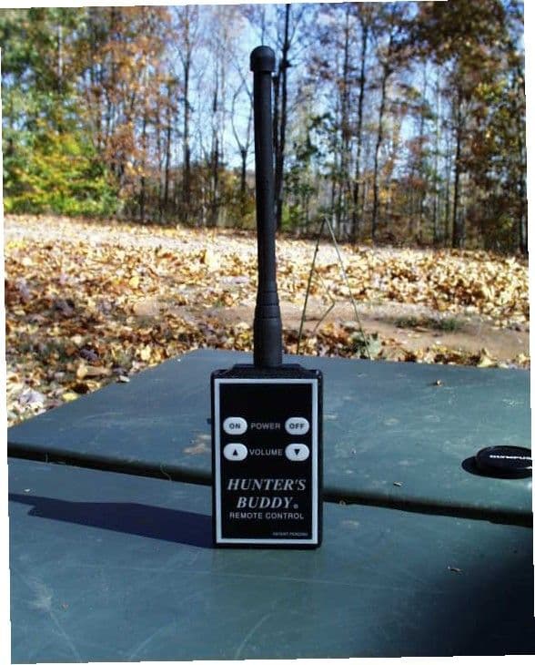
Click to zoom
Application Details
- Equipment Class
- DSC - Part 15 Security/Remote Control Transmitter
- Date of Grant
- Nov 27, 2001
- Application Purpose
- Original Equipment
- Date of Application
- Nov 27, 2001
- Equipment Note
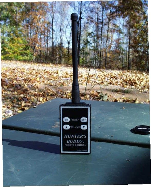
- Predator Caller
- Frequency Range
- 433.90000000 - 433.94000000
- Company
- Hunter's Buddy LLC
- Country
- United States
Documents & Files
Document Text
Text extracted from the exhibit documents filed with the FCC. Open a document above to read the original.
Users Manual
HUNTERS BUDDY MANUAL WARNING! Changes or modification to this equipment may void the user’s authority to operate this equipment. 24
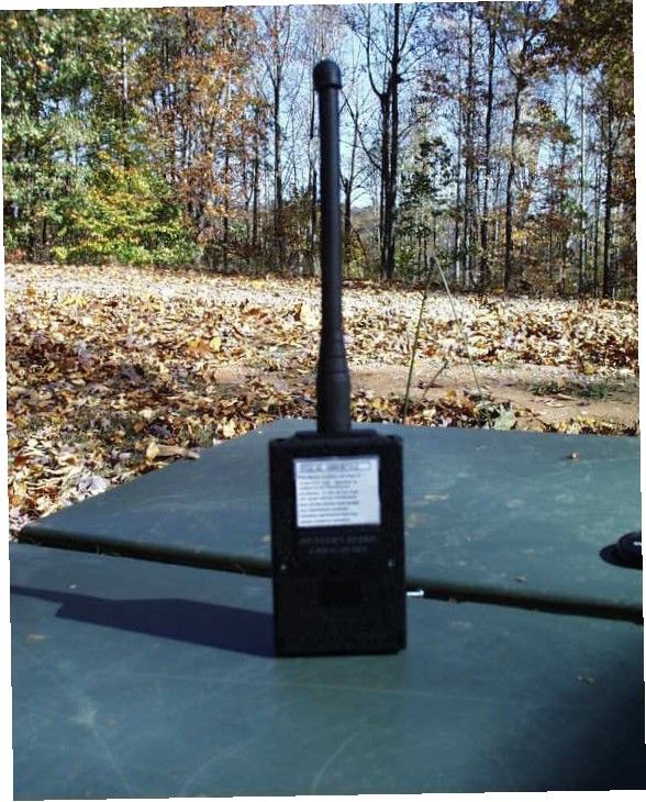
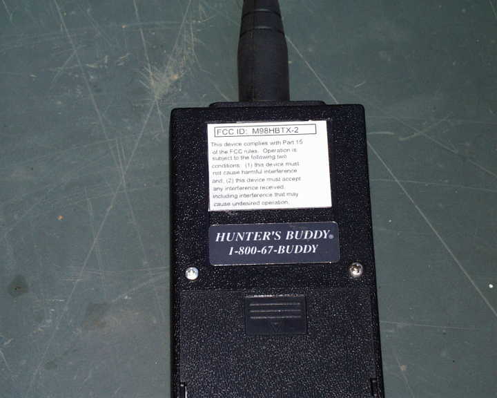
ID Label/Location Info
1.130" cause undesired operation, including interference that may and, (2) this device must accept not cause harmful interference conditions: (1) this device must subject to the following two of the FCC rules. Operation is This device complies with Part 15 FCC ID: M98HBTX-2 1 1 of Sheet Filename Drawn by Date 2:1 Rev Model ScaleTitle 4321 AB CD 1234 D C B A HUNTERS BUDDY any interference received, TRANSMITTER LABEL HBTX-2 12-OCT-01 D hblabel 1.425"
Operational Description
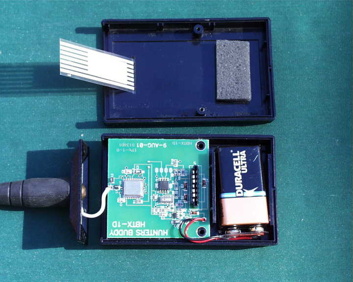
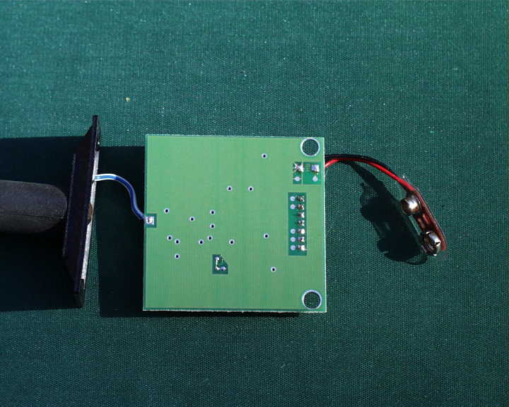
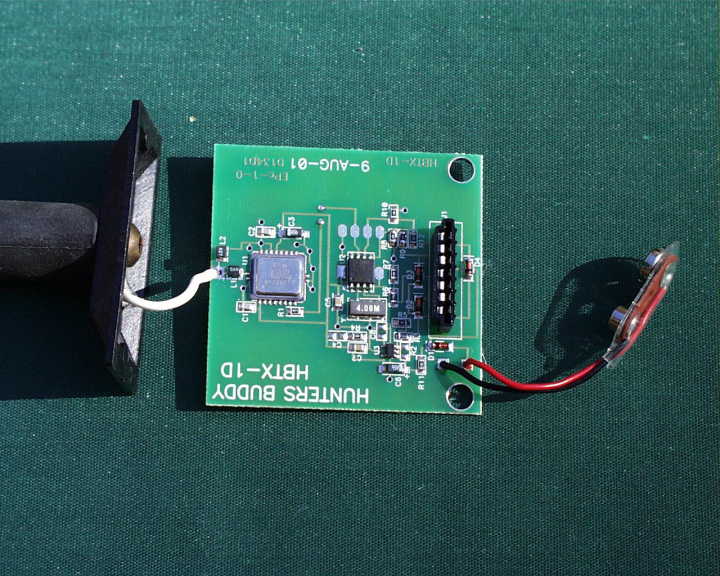
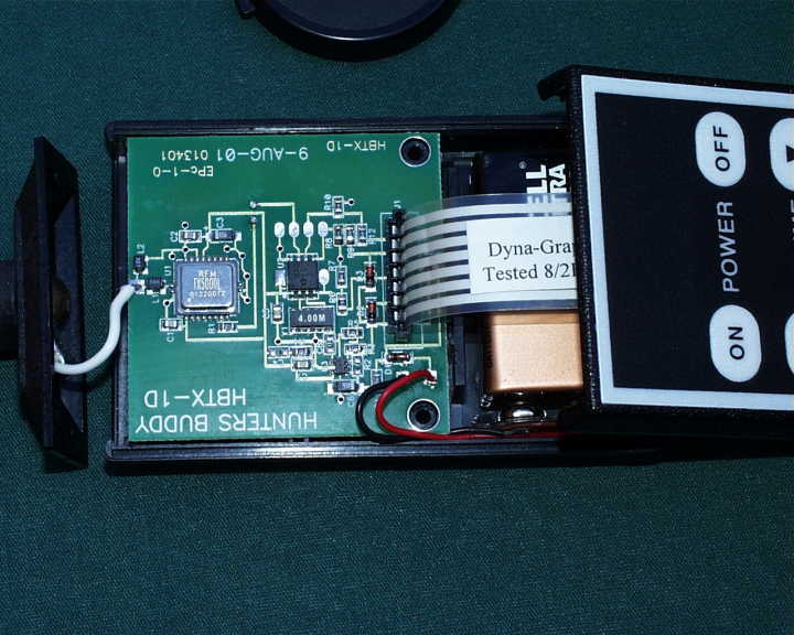
Page 1 HUNTERS BUDDY HBTX-2 CIRCUIT DESCRITION Referring to the schematic: Power is provided by B1, a standard 9 volt, zinc-carbon or alkaline battery. Voltage from the battery is directly connected to regulator, U3, which is disabled in the quiesent state. Current in the quiesent state is <1 μ A. Engaging any of the membrane switches, S1–S4, will pull resistor, R3, high, enabling the regulator output providing power to the micro- controller, U2, and to the transmitter hybrid, U1. The output of the regulator is 3.3 volts, nominal. The encoded control signals are output at pin 7 of U2, and applied to the modulation/data input, pin 8 of U1, through resistor, R1. The rf output from U1 appears at pin 20 and is coupled to the antenna through the matching network, L1, L2.
Schematics
9V B1 ML4148 D1 0 ohms R11 C2 100P C3 4.7uF 4.7uF C6 S2S3S4S1 U3 LP2981 ENABLE 3 N/C 4 V OUT 5 V IN 1 GND 2 R3 20K ML4148 D4 ML4148 D3 ML4148 D2 U1 TX5000L N/C 11 GND2 10 RFOUT 20 GND1 1 VCC1 2 N/C 3 N/C 4 N/C 5 N/C 6 N/C 7 DATAIN 8 N/C 15 N/C 14 N/C 13 N/C 12 GND3 19 CNTL0 18 CNTL1 17 VCC2 16 N/C 9 3.6K R1 TP5 L1 56nH L2 270nH ANTENNA C1 100P 270K R6 R9 20K 20KR12 R10 1M R8 1M 12C508A U2 V- 8 V+ 1 GP0 7 GP1 6 GP2 5 GP3 4 32 Y1 4MHz. GND R7 1M TP1 TP2 TP3 TP4 BR hbtx-2.S01 9-AUG-01 11 D HBTX-2 SCHEMATIC HUNTERS BUDDY ONOFFDOWNUP A BC D 4 321 D C B A 1 2 3 4 B Rev Number TitleSizeDateFilename Drawn by of Sheet
Test Report
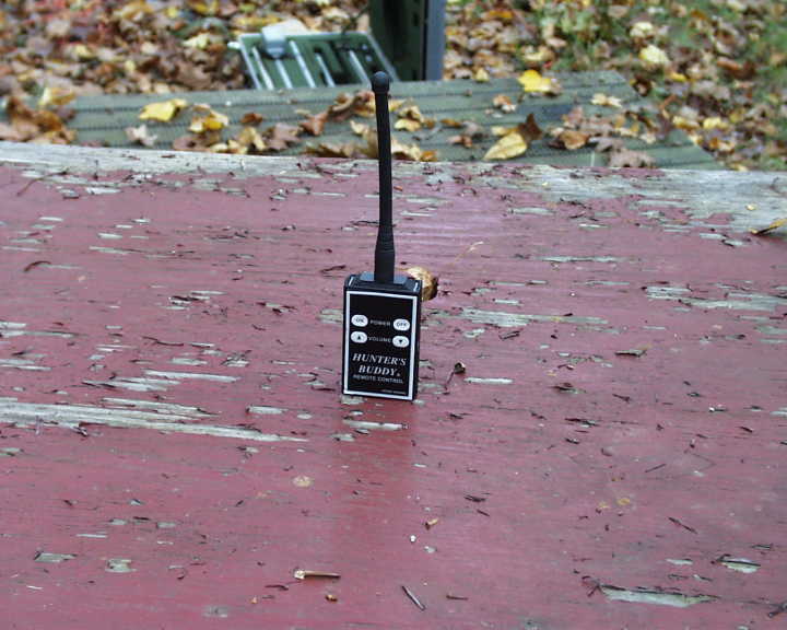
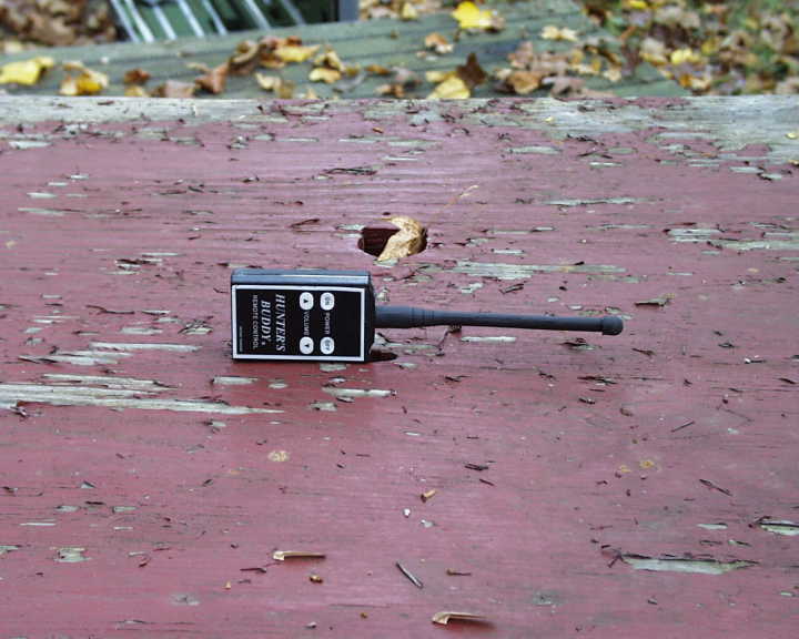
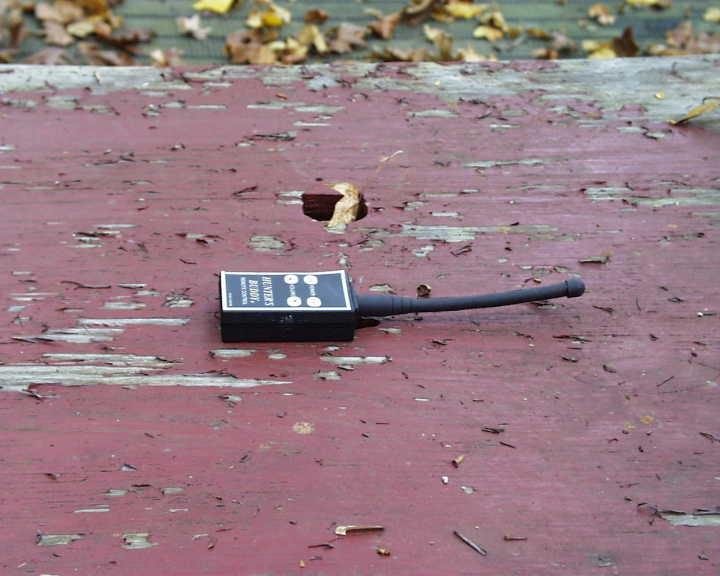
M98HBTX-2 1 Test Report DUT:Remote Control transmitter Model:HBTX-2 Test Date:22-Oct-2001 Manufacturer:Hunters Buddy Rt. 1, Box 284-C2 Sheridan, AR 72150 Conducted by:Control Design & Testing, Inc. 6010 Red Fox Drive Spotsylvania, VA 22553 (540) 582-2826 M98HBTX-2 2 CD&T FCC ID: M98HBTX-2 A. DEVICE UNDER TEST The product is a transmitter used to remotely operate an electronic predator calling system. The caller system contains an integral receiver (M98HB250RX) that has been previously certified. This device is a replacement model for a previously certified transmitter (M98HB250TX). The device is designed to operate under the provisions of Part 15.231 of the FCC rules. The transmit frequency is 433.92 MHz. nominal. The modulation mode is on/off keying using a pulse position code format. This device is manually activated by momentary closure membrane switches. Transmission occurs only when a switch is pressed and ceases immediately when the switch is released. Power for the device is provided by an internal 9 volt battery. The rf section consists of an RF Monolithics TX5000L transmitter IC and a two element antenna matching network. The antenna is a custom manufactured, quarter wave, rubber cased wire and is soldered directly to the printed circuit board. There is no provision to connect a different antenna. B. MEASUREMENT PROCEDURE: RADIATED EMISSIONS Testing of this device was conducted at the Hyak Laboratory test facility located in Spotsylvania, Virginia. Transmitter field strength measurements were conducted according to the procedures set forth in ANSI C63.4 (1992). Testing was conducted with a fresh battery and monitored periodically to insure that the battery voltage (under load) was maintained at 95% of nominal or greater. The device under test was placed on a rotating turntable 0.8 meters high, centered at 3 meters distant from the measurement antenna. The device was placed in the center of the turntable and tested in three positions as shown in the test setup photographs. M98HBTX-2 3 For testing, the sample was set to transmit the “ON” code continuously by holding the button down with a nylon tie wrap and a small piece of plastic. The occupied bandwidth plot below was also captured using the “ON” code. The plots for the occupied bandwidth and time domain measurements were taken using an HP8596E spectrum analyzer and plotted on an HP7475A pen plotter. Occupied Bandwidth The field strength measurements were taken using an HP8596E spectrum analyzer, an EMCO 3121C dipole set, an EMCO 3115 double ridge guide horn and an Avantek UJ210 preamp. The device was scanned from 30 MHz. to 5 GHz. and all emissions were noted. The only emissions detected were those harmonically related to the fundamental transmit frequency. M98HBTX-2 4 At each detected emission frequency, the device was measured by rotating the turntable and adjusting the antenna height over a range of 1 to 4 meters to obtain the maximum output level. This procedure was performed with both horizontal and vertical antenna polarizations for each of the test positions shown in the setup photos. The peak reading for each frequency was recorded in the fourth column in Table 1 below. Measurements taken for weak emissions were performed by reducing the distance from the measurement antenna to 1 meter and factoring –9.54dB into the calculation. This method was used for the 7 th and 8 th harmonics. Any emissions above the 8 th harmonic were either at or below the noise floor. C. DUTY CYCLE CALCULATIONS This device uses a pulse position encoding scheme consisting of six, 750 μ sec. pulses per packet. The packets are 26.90 msec. long from the rising edge of the first pulse to the falling edge of the sixth pulse. The packets are repeated at 53.35 msec. intervals thus only 12 pulses are present in any 100 msec. time frame. CLIENT: HUNTERS BUDDYFCC ID: M98HBTX-2 EUT: CONTROL TRANSMITTER PART 15.231TEST DATE: 22-OCT-01 Ant. Polar. H/V 433.936H23.2-33.220.070795707910997 867.872V30.0-76.7420.010301031099 1301.808V27.6-94.0820.010611500 1735.744H29.7-96.1720.0106111099 2169.681V31.6-98.2220.010410500 2603.617V33.1-104.0320.06461099 3037.553H34.0-109.5120.03841099 3471.490H35.2-116.9220.01821099 Table 1 RADIATED EMISSIONS DATA Frequency In MHz. Peak Power uV/m@3m Peak reading dBm Ant. Factor dB ANTENNA: DIPOLES/DRG HORN Duty Cycle -dB FCC Limit uV/m@3m Corrected Power uV/m@3m M98HBTX-2 5 The calculation for the duty cycle correction factor is: 12 pulses X 750 μ sec. = 9.0 msec. 20log (9.0msec./100msec.) = -20.915dB. As provided in Part 15.35 of the FCC rules, a correction factor of –20dB is used for the calculations in Table 1 above . Plot 1 M98HBTX-2 6 Plot 2 Plot 3 -
Contact Information
Applicant
Randall Bruce Muckelrath(President)
Test Firm
Hyak Laboratories, Inc.Rowland Johnson
703-451-1188
Technical Specifications
| # | Rule Parts | Frequency Range | Power Output |
|---|---|---|---|
| 1 | 15.231 | 433.9 MHz - 433.94 MHz | - |
Other Applications from Hunter's Buddy LLC
M98HB250TX
Dec 04, 1996Predator Calling System Transmitter
Equipment Class
DSC - Part 15 Security/Remote Control TransmitterM98HB250RX
Dec 03, 1996Predator Calling System Receiver
Equipment Class
CYY - Communications Receiver used w/Pt 15 Transmitter