MBMACC100V2FM Transmitter
Progressive Concepts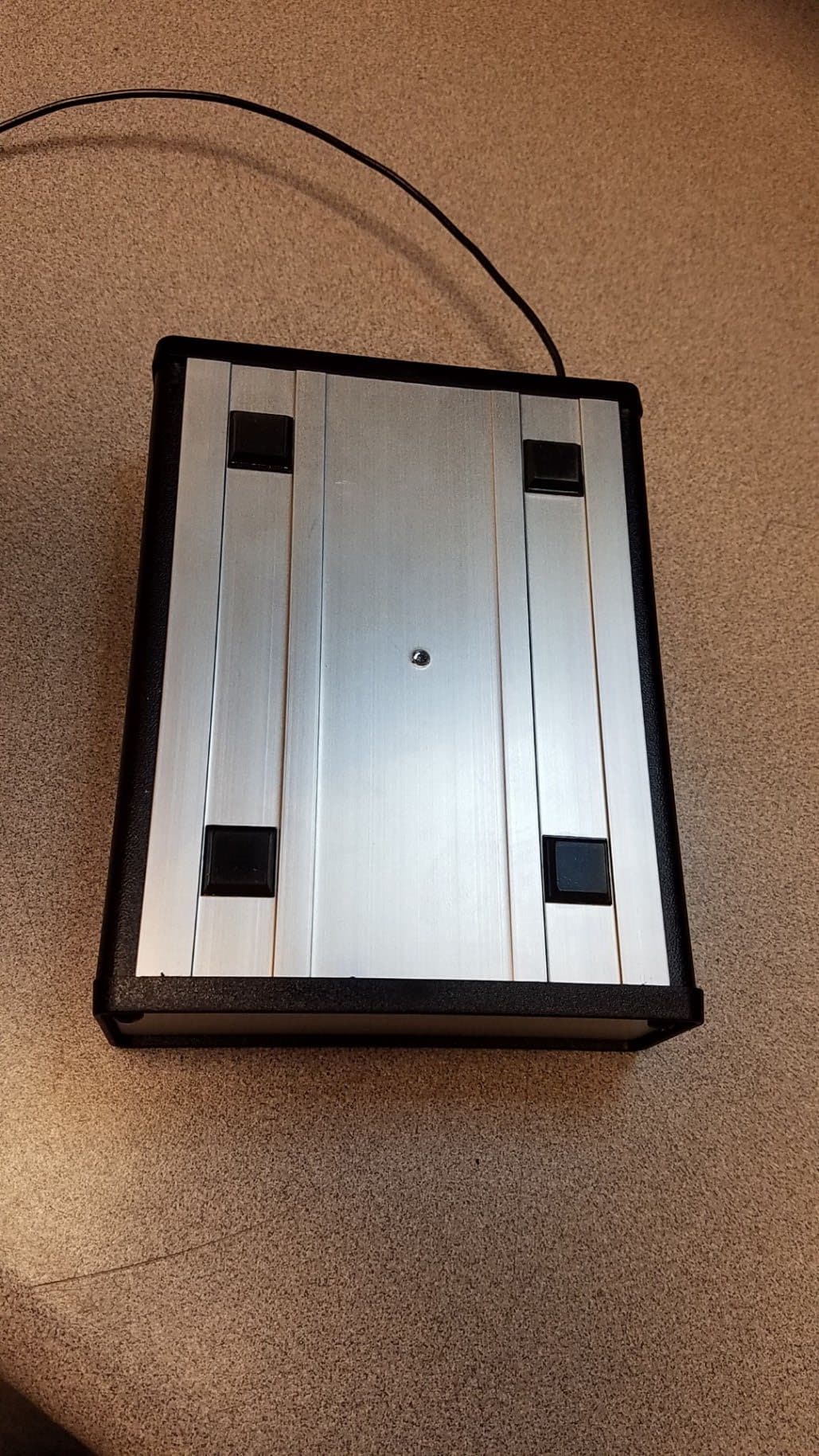
Click to zoom
Application Details
- Equipment Class
- DXX - Part 15 Low Power Communication Device Transmitter
- Date of Grant
- Feb 24, 2022
- Application Purpose
- Original Equipment
- Date of Application
- Feb 24, 2022
- Equipment Note
- FM Transmitter
- Frequency Range
- 88.00000000 - 108.00000000
- Company
- Progressive Concepts
- Country
- United States
Documents & Files
Document Text
Text extracted from the exhibit documents filed with the FCC. Open a document above to read the original.
Users Manual
ACC100 & ACC100S V2 Models Low Power FM Broadcaster From Progressive Concepts, Made in the USA. The ACC100V2 is a quartz stabilized microprocessor and phase-locked-loop DIRECT FM modulated transmitter. This unit provides short range broadcasting to any FM receiver including auto radios and portable radios. Typical applications include: (1) Advertising of homes for sale, or products for sale, to passing automobiles (2) Broadcast of church services and/or PA systems to parking lots or hearing impaired (3) Re-broadcast of TV sound to institutional inmates equipped with portable radios and earphones, then switching off speakers to reduce ambient noise levels – several TV’s may be operated in an area without sound interference. Specifications: Frequency 87.9 MHz to 107.9 MHz in discreet 100KHz increments Radio Output FCC Part 15 & IC operation, 250 microvolts per meter at 3 meters Harmonics -40 dB or better across band Channels Selected by direct-reading rotary switches Audio Response 40Hz to 20KHz (mono) Audio Input RCA Input Jack (-10dB) Audio Level Line level, typical of TV, VCR, CD and PA system output Power Supply 12 volts, 100 ma. DC wall adapter (supplied) Circuit Board 2-sided epoxy glass, extremely rugged Size & Weight 1.5” x 4.1” x 5.5”, 13 ounces Antenna 24-inch fixed-length wire Range 50 to 200 feet dependent on sensitivity of the receiver Warranty & Repair This device is warranted for a period of two years from date of sale against defects in materials and workmanship. The user should not attempt repair or modification of this device. Contact customer support if you experience problems or need repairs. Progressive Concepts [email protected] 305 South Bartlett Road Streamwood, IL 60107 (630) 736-9822 (630) 736-0353 fax This device complies with CFR Title 47, Part 15 of the FCC Rules governing the use of low power radio frequency devices. It may be operated on the FM band without a license. Operating range may vary from 50 to several hundred feet depending on the sensitivity of the receiver. Operation must cease if this unit causes interference to licensed radio stations; however, it is not protected from receiving interference. Internal modification or change in the length of the fixed- wire antenna may void FCC certification. ACC100V2 – Low Power FM Broadcaster page 2 Frequency Selection The operating frequency is selected by the rotation of 3 switches accessible through the left side of the rectangular cutout on the rear panel of the enclosure. The circuit’s microprocessor accepts only frequencies between and including 87.9 MHz and 107.9 MHz. Any other setting is invalid and will default automatically to 88.1 MHz. Example of switch setting S1 S2 S3 (10’s) (1’s) (.1’s) (Invalid) 7 9 6 88.1 MHz (default) (Valid) 8 7 9 87.9 MHz (Valid) 8 8 1 88.1 MHz (Valid) 9 1 5 91.5 MHz (Valid) 0 7 9 107.9 MHz (Invalid) 0 8 0 88.1 MHz (default) Frequency of operation Select a channel which will not interfere with the reception of a commercial FM station and which will not interfere with your reception of the ACC100. These should be frequencies end- ing with .1, .3, .5, .7, or .9 Stagger individual frequencies when several ACC100’s are used in the same area, usually 3 to 5 channels apart will suffice such as 98.1, 98.9, 99.7, 100.5, etc. After the frequency has been set, disconnect the power supply for 5 seconds. The ACC100 will return to the set frequency automatically when ever it is switched on and when power is re- stored after a power outage. Line Level Audio (approximately 1 volt peak to peak) Simply connect the ACC100 to your audio source with the supplied RCA audio cable. If reception appears distorted you may have an audio level greater than required. Placing a resistor in series with the audio source may reduce the audio to an acceptable level. A typical resistor value might be 1000 Ohms. Audio from a PA or speaker system In the absence of a line level audio source you may connect the audio input of the ACC100 to wires normally connected to a speaker. Be sure to read the WARNING section on page 3 if you connect to speaker wires. Stereo connections The ACC100 is a monaural broadcaster. Some audio sources (TV’s) permit switching to a monaural output. If you have a stereo source that cannot be switched to monaural then you may use the mixing circuit shown on page 3. The model ACC100S is a Stereo unit. ACC100V2 – Low Power Broadcaster Page 3 Speaker leads, where one lead is common to “ground” or to the equipment chassis, and is not “hot” as described above, may be connected by way of an RCA plug and cable. You must assure the speaker ground connects to the cable shield (shell of RCA plug). Speaker leads where both leads are “floating” and no common or chassis connection exists should use a “balanced” audio connection. There are several types of external audio “BALUNS” that can be bought at most electronic stores such as Best Buy or Guitar Center. When such an audio Balun is installed in line with the audio input then neither audio lead connects to the chassis. If required, the following circuit combines stereo channels to produce a balanced monaural output. Resistors are 100 -1000 Ohms each. If the sources are speaker leads, where the speaker is disconnected, you may want to terminate the leads with 5 watt resistors equal to the impedance of the removed speakers – typically 8 or 16 Ohms. WARNING: You may ignore this warning if you use an audio source with an “RCA” output jack. These are typically used on consumer type audio equipment. When attempting to derive audio from speaker output terminals, or from speaker wires, you must assure the source equipment is not electrically “hot”. Some equipment, especially radio and TV receivers, have internal switching power supplies, which may connect the equipment to one side of the AC power line. Touching the chassis, or any conducting device connected to the chassis, could result in a lethal electrical shock. Therefore, if you intend t…
Text truncated - open the document above for the full version.
Cover Letter(s)
Progressive Concepts 305 South Bartlett Road Streamwood, IL 60107 630.736.9822 Fax 630.736.0353 [email protected] www.progressive-concepts.com Federal Communications Commission Authorization and Evaluation Division 9/14/2021 Confidentiality Request regarding application for certification of FCC ID: MBMACC100V2 Pursuant to Sections 0.457 and 0.459 of the Commission's Rules, we hereby request confidential t reatment of information accompanying this application as outlined below: Exhibit Type Schematic Block Diagram C ircuit Description The a bove materials contain trade secrets and proprietary information not customarily released to the public. The public disclosure of these materials may be harmful to the applicant and provide unjustified benefits to its competitors. Th e applicant understands that pursuant to Section 0.457 of the Rules, disclosure of this application a nd all accompanying documentation will not be made before the date of the Grant for this application. Pursuant to DA04-1705 June 15, 2004 of the Commission's public notice, we also request temporary confidential treatment of information accompanying this application as outlined below for 180 days. Exhibit TyP-e I nternal Photos User manual Sincerely, Eric D. Hoppe The best in radio broadcast electronics since 1990
Cover Letter(s)
Progressive Concepts 305 South Bartlett Road Streamwood, IL 60107 630.736.9822 Fax 630.736.0353 [email protected] www.progressive-concepts.com Timco Engineering, Inc. 849 N.W. State Road 45 P.O. Box 370 Newberry, FL 32669 9/13/2021 SUBJECT: Application(s) for Certification for FCC ID: MBMACC100V2 IC: 27718-MACC100V2 To Whom It May Concern: We, the undersigned, hereby authorize Sharon Hoffman at TIMCO ENGINEERING, INC. on our behalf, to apply for certification on our equipment referenced above. Any and all ac ts carried out by TIMCO ENGINEERING, INC. on our behalf shall have the same effect as acts of our own. This is to advise that we are in full compliance with the Anti Drug Abuse Act. We, the applicant, ar e not subject to a denial of federal benefits pursuant to Section 5301 of the Anti-Drug Act of 1988, 21 USC853a, and no party to the application is subject to a denial of federal benefits pursuant to t hat section. Regards, . / /] �/77Vv c=::--=- Eric Hoppe The best in broadcast electronics since 1990
External Photos
Progressive Concepts FCC ID: MBMACC100V2 IC: 27718-MACC100V2 External Photos FRONT VIEW BACK VIEW TOP VIEW BOTTOM VIEW SIDE VIEW SIDE VIEW
ID Label/Location Info
Label Location and label sample
Internal Photos
Progressive Concepts FCC ID: MBMACC100V2 IC: 27718-MACC100V2 Internal Photos
Test Report
Timco Test Report # TR_4638-21_FCC_15. 239_3 Revision: 3 Final Test Date: 1/5/2022 Issue Date: 2/10/2022 An IIA Company Te s t Report – FCC 15.239/ISED RSS-210 Intentional Radiator Applicant: Progressive Concepts Approved for Release By: Signature: Name & Title: Bruno Clavier, General Manager Date of Signature 1/18/2022 This test report shall not be reproduced except in full without the written and signed permission of Timco Engineering Inc. (IIA). This test report relates only to the items tested as identified and is not valid for any subsequent changes or modifications made to the equipment under test. Timco Engineering, Inc., an IIA Company 849 NW State Road 45, Newberry, Florida 32669 (352) 472-5500 / [email protected] Page 2 of 21 This test report shall not be reproduced except in full without the written and signed permission of Timco Engineering Inc. (IIA). Table of Contents 1. CUSTOMER INFORMATION ........................................................................................................................................................................... 3 1.1 TEST RESULT SUMMARY ............................................................................................................................................................................................ 3 2. LOCATION OF TESTING ................................................................................................................................................................................. 4 2.1 TEST LABORATORY ....................................................................................................................................................................................................4 2.2 TESTING WAS PERFORMED, REVIEWED BY ................................................................................................................................................................ 5 3. TEST SAMPLE(S) (EUT/DUT) ........................................................................................................................................................................... 6 3.1 DESCRIPTION OF THE EUT ........................................................................................................................................................................................ 6 3.2 CONFIGURATION OF EUT ......................................................................................................................................................................................... 7 3.3 TEST SETUP OF EUT .................................................................................................................................................................................................. 7 4. TEST METHODS & APPLICABLE REGULATORY LIMITS ............................................................................................................................ 8 4.1 TEST METHODS/STANDARDS/GUIDANCE ................................................................................................................................................................ 8 5. MEASUREMENT UNCERTAINTY .................................................................................................................................................................... 8 6. ENVIRONMENTAL CONDITIONS ................................................................................................................................................................. 8 7. LIST OF TEST EQUIPMENT AND TEST FACILITY ........................................................................................................................................ 9 8. TEST RESULTS ................................................................................................................................................................................................. 10 8.1 OCCUPIED BANDWIDTH .................................................................................................................................................................................. 11 8.1.1 Test Data: 99% OBW Plot, 88.1 MHz ............................................................................................................................................... 12 8.1.2 Test Data: 99% OBW Plot, 91.5MHz ................................................................................................................................................. 13 8.1.1 Test Data: 99% OBW Plot, 107.9MHz .............................................................................................................................................. 14 8.2 RADIATED SPURIOUS EMISSIONS ............................................................................................................................................................................ 15 8.2.1 Test Data: Measurement Table, Fundamental .............................................................................................................................. 16 8.2.2 Test Data: Measurement Table, 88.1 MHz ...................................................................................................................................... 17 8.2.1 Test Data: Measurement Table, 91.5 MHz ...................................................................................................................................... 18 8.2.2 Test Data: Measurement Table, 107.9 MHz ................................................................................................................................... 19 9. ANNEX-A - PHOTOGRAPHS OF THE EUT............................................................................................................................................... 20 10. ANNEX-B – TEST SETUP PHOTOGRAPHS ............................................................................................................................................... …
Text truncated - open the document above for the full version.
Test Setup Photos
ANNEX B – Test Setup Photograph Exhibit Progressive Concepts Model: ACC100V2 FCC ID: MBMACC100V2 IC: 27718-MACC100V2 Radiated Testing, Table Setup Radiated Testing, Below 1 GHz Radiated Testing, Below 1 GHz #2
Contact Information
Applicant
Eric Hoppe
Test Firm
Timco Engineering, Inc.Bruno Clavier
Technical Specifications
| # | Rule Parts | Frequency Range | Power Output |
|---|---|---|---|
| 1 | 15C | 88 MHz - 108 MHz | - |