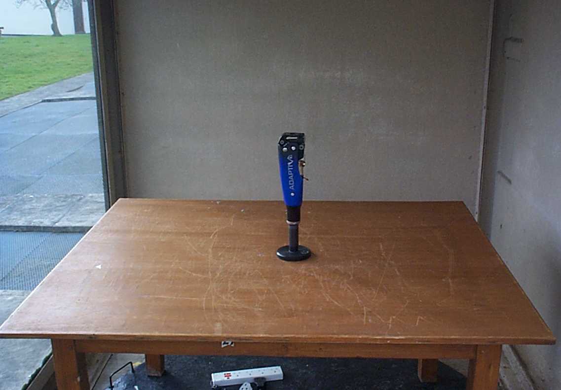
MF3019174Adaptive Limb
Chas A Blatchford & Sons Ltd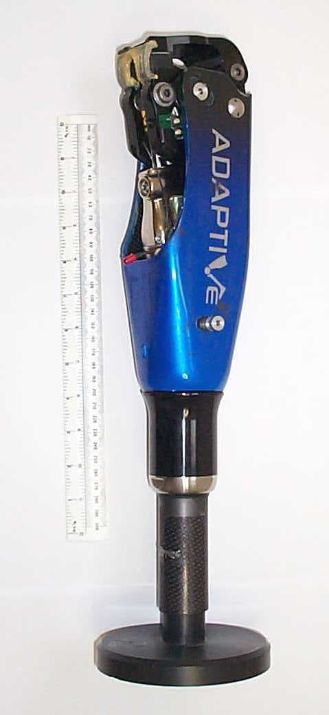
Click to zoom
Application Details
- Equipment Class
- DSR - Part 15 Remote Control/Security Device Transceiver
- Date of Grant
- Apr 04, 2002
- Application Purpose
- Original Equipment
- Date of Application
- Apr 04, 2002
- Equipment Note
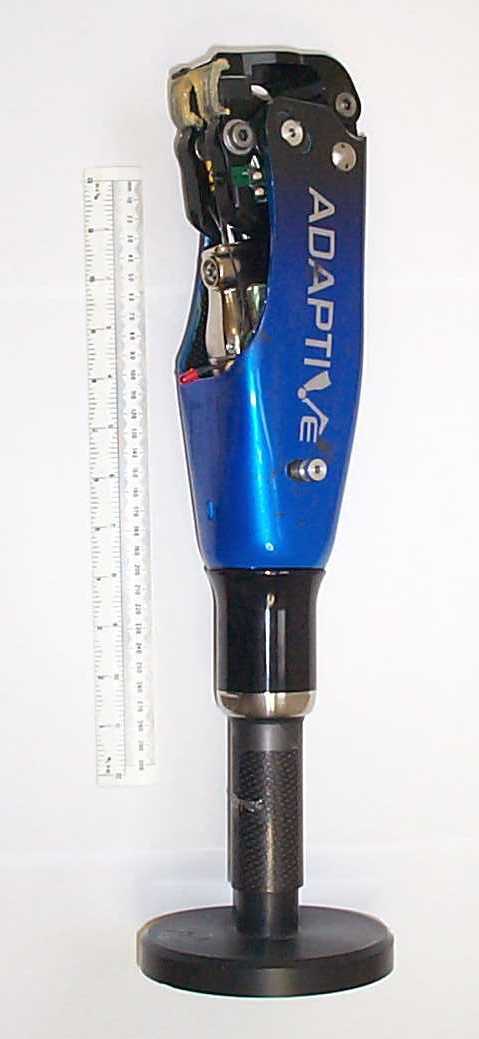
- Adaptive Limb
- Frequency Range
- 914.13000000 - 914.90000000
- Company
- Chas A Blatchford & Sons Ltd
- Country
- United Kingdom
Documents & Files
Document Text
Text extracted from the exhibit documents filed with the FCC. Open a document above to read the original.
Users Manual
ENA938141-C-01-2002 Technical Data Weight (standard demountable version)1495g Maximum flexion angle (this angle may be limited by socket size and alignment) Non-rechargeable battery pack – wired, fused, with diode - Lithium CR123A x 3 - nominal 9V Single bolt proximal alignment, 35mm dia. demountable tube clamp distal attachment or TT Shock Pylon option. Operating temperature range The user shall be aware that changes or modifications not expressly approved could void the operating licences and exemptions. This device complies with part 15 of the FCC Rules. Operation is subject to the following two conditions:- 1)This device may not cause harmful interference. 2)This device must accept any interference received, including interference that may cause undesired operation. Getting Started Next Main Menu
Cover Letter(s)
PRODUCTS DIVISION Chas A Blatchford & Sons Ltd Products Division Lister Road Basingstoke Hampshire RG22 4AH United Kingdom Telephone: +44 (0)1256 316600 Facsimile: +44 (0)1256 810450 FM29097 ISO9001 Directors: B. S. Blatchford M.Sc., B.A. (Oxon) M. J. Blatchford J. J. Shorter I.M. R. G. Coxford C.B.E. P. A. Lewis M.B.A.P.O. Dr J. Watkinson A. J. Neilson M.B.A. T. Hauxwell M.A. (Hons) A.C.M.A. Registered in England No. 162114 VAT Registration No. 198 9476 78 Request for Confidentiality 5 th March 2002 TRL Compliance Services Ltd Long Green Forthampton Gloucester GL19 4QH UK RE:Certification Application FCC ID:MF3019174 To Whom It May Concern: Please be advised that the following information is to be held confidential on behalf of Chas. A. Blatchford & Sons Ltd. • Adaptive Limb Module Technical Description • Limb Module Block Diagram • Adaptive Controller Block Diagrams • Adaptive Controller Circuit Diagram • Adaptive Interface Circuit Diagram The application contains technical information which Chas. A. Blatchford & Sons Ltd deems to be trade secrets and propriety. If made public, the information might be used to the disadvantage of the applicant in the market place. Thank you for your attention to this matter. Yours Faithfully Chas. A. Blatchford & Sons Ltd Andrew John Sykes Electronic Design Engineer
Cover Letter(s)
PRODUCTS DIVISION Chas A Blatchford & Sons Ltd Products Division Lister Road Basingstoke Hampshire RG22 4AH United Kingdom Telephone: +44 (0)1256 316600 Facsimile: +44 (0)1256 810450 FM29097 ISO9001 Directors: B. S. Blatchford M.Sc., B.A. (Oxon) M. J. Blatchford J. J. Shorter I.M. R. G. Coxford C.B.E. P. A. Lewis M.B.A.P.O. Dr J. Watkinson A. J. Neilson M.B.A. T. Hauxwell M.A. (Hons) A.C.M.A. Registered in England No. 162114 VAT Registration No. 198 9476 78 Manufacturer’s Letter 5 th March 2002 TRL Compliance Services Ltd Long Green Forthampton Gloucester GL19 4QH UK RE:FCC labelling Requirements FCC ID:MF3019174 To Whom It May Concern: Please be advised that the manufacturer will ensure that the above-referenced model will be manufactured in accordance with the FCC Rules and Regulations. Thank you for your attention to this matter. Yours Faithfully Chas. A. Blatchford & Sons Ltd Andrew John Sykes Electronic Design Engineer
ID Label/Location Info
PRODUCTS DIVISION Chas A Blatchford & Sons Ltd Products Division Lister Road Basingstoke Hampshire RG22 4AH United Kingdom Telephone: +44 (0)1256 316600 Facsimile: +44 (0)1256 810450 FM29097 ISO9001 Directors: B. S. Blatchford M.Sc., B.A. (Oxon) M. J. Blatchford J. J. Shorter I.M. R. G. Coxford C.B.E. P. A. Lewis M.B.A.P.O. Dr J. Watkinson A. J. Neilson M.B.A. T. Hauxwell M.A. (Hons) A.C.M.A. Registered in England No. 162114 VAT Registration No. 198 9476 78 FCC Labelling Requirements and Information 5 th March 2002 TRL Compliance Services Ltd Long Green Forthampton Gloucester GL19 4QH UK RE:FCC labelling Requirements FCC ID:MF3019174 The following label information is required by the FCC Rules and Regulations for certified devices. Please find below images of the marking information required by the FCC Rules and Regulations. Thank you for your attention to these matters. Yours Faithfully Chas. A. Blatchford & Sons Ltd Andrew John Sykes Electronic Design Engineer FCC ID. MF 3019174
Operational Description
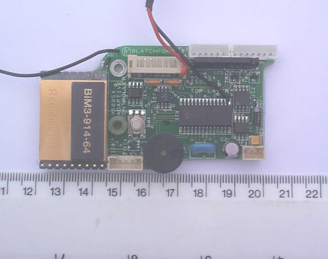
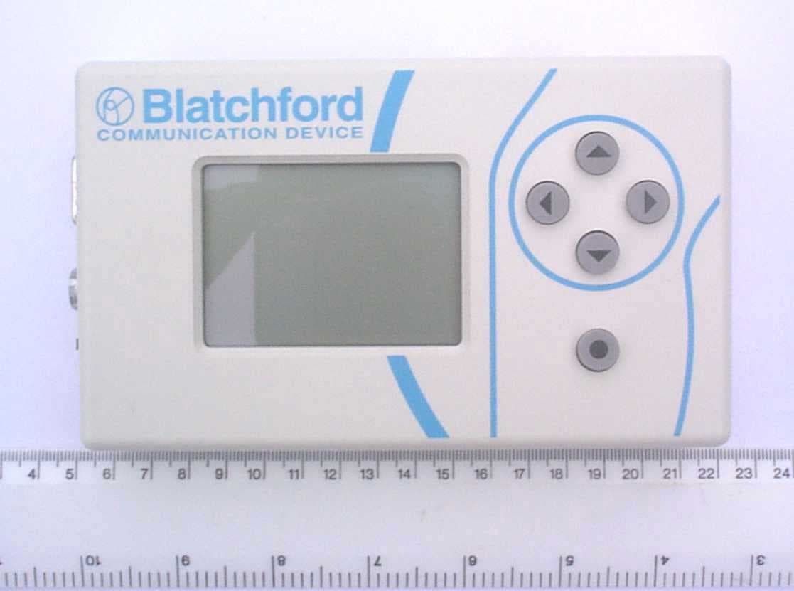
Adaptive Limb Module Technical Description Product Description The Adaptive Limb Module is a prosthetic device designed to provide stance and swing control for Transfemoral amputees. The module contains electronic circuitry to control hydraulic and pneumatic valves such that the stance and swing characteristics can be modified to optimise an amputee’s gait. The control circuitry within the Adaptive Limb automatically selects the levels of stance phase support and swing phase assistance according to the type of terrain and walking speed. The limb control parameters are set up for each amputee during the limb fitting using the Communication Device. High stability support can be programmed for individuals with poor musculature whilst a lower level of support can be programmed for users with greater control of their own residual musculature. The prosthesis provides stance control ranging from minimal resistance to a yielding lock. It uses sensors to detect different modes; level walking, ramp descent, stair descent, sitting, standing and instances where stumble occurs. The stance resistance is set to a pre- programmed level for the different modes and these levels match the amputee’s ability to control the limb. Technical Description The control cylinder, which determines how the Adaptive Limb module swings about the knee joint, comprises of two chambers, one hydraulic and one pneumatic. Each chamber has a motorised valve enabling different hydraulic and pneumatic resistances to be set under electronic control. The module contains two sensors, one to monitor the angle of limb flexion and the other to monitor the vertical load applied to the limb. The inputs from the two sensors are continually processed by a microcontroller situated within the limb module to determine the mode of locomotion. The positions of the pneumatic and hydraulic control valves are set according to the pre-programmed parameters of the selected mode. Communication between the limb and the Communication Device is via a bi-directional 914MHz low power radio link. Once the limb has been programmed at a limb fitting centre the power to the transceiver on the limb is disabled. The 914MHz radio link is implemented in both the Adaptive Limb and Communication Device using a proprietary transceiver module. The module is supplied by Radiometrix, part number BiM3-914-64. Both the Adaptive Limb and Communication Device are designed to be powered from nominal 9 volt battery supplies. Modes of Operation a) Communication Device The Communication Device is only used during the fitting stage of the artificial limb for programming and monitoring of function. During this fitting stage the Communication Device sends and receives rf data messages initiated by the operator. b) Adaptive Limb There are six activity states which each have a programmable hydraulic resistance setting. The activity states are standing, sitting, walking on a level surface, walking down a ramp, walking down stairs and stumble. For the walking on a level surface and ramp modes the pneumatic resistance is increased with walking speed. For stairs descent mode it is set to a maximum, for standing and sitting modes to a minimum and for stumble mode the currently selected pneumatic resistance is retained. Adaptive Limb Module Technical Description i) Set Up (Program) Mode During the fitting stage of the limb the hydraulic and pneumatic resistance levels are programmed and the activity state selection thresholds determined. This programming sequence would normally be carried out by a practitioner using the Communication Device to remotely interact with the limb to make the necessary adjustments to the activity state detection and control parameters. Once the limb has been programmed to meet the amputee’s particular gait characteristics all data to activate the activity states is retained in non-volatile memory on the limb controller circuit board. The rf transceiver on the limb is powered on by a specific activation sequence to enable communication between the limb and Communication Device. Once the fitting is complete the rf transceiver is automatically disabled. ii) Normal Operation The limb provides stance and swing control for the amputee as he or she goes about their daily function. The force and swing sensors are continually monitored and the measured data is processed to determine the current activity state. The motorised hydraulic and pneumatic valves are then driven to the corresponding positions determined in set up mode to activate the required hydraulic and pneumatic resistance settings. RF Communication Protocol A bi-directional RF 914MHz communication link is set up between the Communication Device and the Adaptive Limb Controller Board. Data is sent in 8 byte packets at data rate of 9600 baud. The structure of the data packet is as follows: channel-channelcommand-commanddata1-data1data2-data2 Each packet contains 4 bytes of information, channel (which is also used as the start byte), command and 2 data bytes and the inverse of each of these bytes making a total of 8 bytes. The inverse bytes are used to check the integrity of the packet. If any of the 2 byte pairs do not verify then the whole data packet is rejected. Before each data packet is sent a 4 byte preamble sequence is transmitted to allow the receiving device to synchronise to the transmitting device. During communication the Communication Device is the master and the Limb Controller is the slave. The default state is Communication Device in transmit mode and Limb Controller in receive mode. The communication protocol timing is as follows: TRANSMIT PACKET SELECT RX MODE COMMUNICATION DEVICE READY TO RECEIVE DATA (TIMEOUT AFTER 64ms) SELECT TX MODE READY TO TRANSMIT LIMB CONTROLLER RECEIVE PACKET SELECT TX MODE WAITTRANSMIT REQUESTED DATA SELECT RX MODE READY TO RECEIVE 12ms4msupto 64ms4ms 12ms4ms4msupto 60ms WAIT 16ms 4ms The Limb Controller will only transmit a data packet in response to a request …
Text truncated - open the document above for the full version.
Operational Description
Adaptive Limb and Communication Device FCC Test Instructions Adaptive Limb Modes of Operation for Test Purposes 1. Simulation of normal walking, activated by initiating the Test Mode on the limb as described below. 2. Communicating with the Communication Device, activated by setting up a communication link as described on the next page. 3. Independent continuous transmission, activated by initiating Continuous Transmission Mode on the limb as described below (this mode has been specifically added for test purposes to assist with set up and is not a valid mode for a limb in normal configuration). Adaptive Limb Test Mode Features The test mode drives the stepper motor and the dc motor in a predetermined repetitive sequence. Whilst this sequence is being followed the red LED flashes on and off at one second intervals. Note: the LED has been included for test purposes only and is not part of the normal limb configuration. If the sequence is disrupted, e.g. a microcontroller reset, then the LED will stop flashing. Test mode can only be re-initiated by reselecting the Test Mode using the buttons on the circuit board located in the knee as described below. The force and swing sensors are also monitored for adverse changes. If such a change is detected the LED is flashed rapidly for 2 seconds then returns to the normal flash rate indicating continuation of the test sequence. Note: on completion of a given test, particularly overnight, to save battery power press and release the lower button on the circuit board located in the knee and confirm that two beeps only are heard. Initiating Test Mode on the Limb 1. Press and release the lower button on the circuit board located in the knee. 2. Wait for two beeps to sound. 3. Press and release the upper button on the circuit board located in the knee. 4. Three beeps should be sounded to confirm that the test mode has been activated. 5. The red LED will flash rapidly for 2 seconds then flash on and off continuously, where the on and off period is one second. Initiating Continuous Transmission Mode on the Limb 1. Press and hold the upper button on the circuit board located in the knee. 2. Press and release the lower button on the circuit board located in the knee. 3. Wait for two beeps to sound. 4. Release the upper button 5. Four beeps should be sounded to confirm that the continuous transmission mode has been activated. Transmission can be confirmed by selecting Transceiver Test as described below. 1. Power on the Communication Device and press the right arrow key to select ADVANCED SETUP. 2. Step down the ADVANCED SETUP menu using the down arrow key until DIAGNOSTICS is highlighted. Then hit the select key (marked with a black circle). 3. Step down the DIAGNOSTICS menu using the down arrow key until TRANSCEIVER TEST is highlighted. Then hit the select key. 4. Press the right arrow key to display the NEAREST channel. 5. If the limb has been set to continuous transmission mode correctly then channel 1 will be selected and RX COUNT will continually increment. Adaptive Limb and Communication Device FCC Test Instructions Communication Device Modes of Operation for Test Purposes 1. Communicating with the Adaptive Limb, activated by setting up a communication link as described below. 2. Independent continuous transmission, activated by selecting Transceiver Test on the Communication Device for a chosen channel as described below. Setting Up a Communication Link between the Communication Device and the Limb The limb can be monitored with the Communication Device during test mode. If program mode is selected via the Communication Device then test mode is terminated and can only be re-initiated using the buttons on the circuit board located in the knee as described above. 1. Initiate test mode on the limb as described above. 2. Power on the Communication Device and press the right arrow key to select ADVANCED SETUP. 3. Step down the ADVANCED SETUP menu using the down arrow key until DIAGNOSTICS is highlighted. Then hit the select key (marked with a black circle). 4. Step down the DIAGNOSTICS menu using the down arrow key until VALVE CHECK is highlighted. Then hit the select key. 5. The VALVE CHECK screen should now be displayed with 2 empty scales, one for the hydraulic valve and one for the pneumatic valve. 6. Press and hold the upper button on the circuit board located in the knee until moving bars are displayed on the hydraulic and pneumatic valve scales. Now release the upper button on the knee. The moving bars represent the positions of the dc motor (hydraulic valve) and stepper motor (pneumatic valve). When in test mode these bars show how the motors move according to the predetermined repetitive sequence. Initiating Continuous Transmission Mode on the Communication Device 1. Power on the Communication Device and press the right arrow key to select ADVANCED SETUP. 2. Step down the ADVANCED SETUP menu using the down arrow key until DIAGNOSTICS is highlighted. Then hit the select key (marked with a black circle). 3. Step down the DIAGNOSTICS menu using the down arrow key until TRANSCEIVER TEST is highlighted. Then hit the select key. 4. Ensure CHOSEN is highlighted (press the left arrow key to select CHOSEN if it isn’t selected already). 5. If selected correctly TX DATA will increment, RX DATA will remain blank and ERRORS will increment with TX DATA (but will remain at 255 when this count is reached whilst TX DATA increments from 0 again). Adaptive Limb and Communication Device FCC Test Instructions Additional Notes Audio Indications A) Audio Indications that Occur Automatically in any Mode • 2 beeps – indicates that an involuntary reset has occurred which disables the pneumatic and hydraulic controls. • 1 short beep every 15 seconds – indicates that the battery supply is low and that the batteries should be replaced/recharged as soon as possible. B) Audio Indications that Occur Automatically in Program Mode Only • Very fast repeating beeps for 2 seconds – i…
Text truncated - open the document above for the full version.
Parts List/Tune Up Info
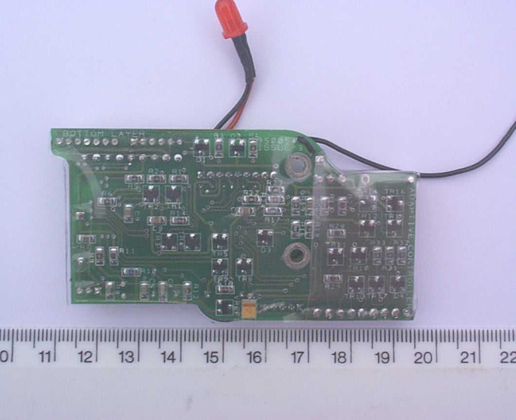
259801 ADAPTIVE CONTROLLER BOARD ISSUE:6COMPONENT LIST Page 1 of 2 RefValueQTYDescription 1PL49WAYPLH1JST 9WAY PLUG HORIZONTAL 2PL16WAYPL1JST 6WAY PLUG VERTICAL 3PL27WAYPL1JST 7WAY PLUG VERTICAL 4PL33WAYPL1JST 3WAY PLUG VERTICAL 5PL55WAYPL1JST 5WAY PLUG VERTICAL 6 7SW1SPNO1SMD KEYBOARD SWITCH 8B13-16V DC1PIEZO AUDIO INDICATOR 9 10C1,C310uf16V2SMD TANT CAP (CASE CODE B) 11C2100uf10V1CAP RUBYCON MH7 (H7, DIA 6.3) 12C4,C533pF100V2CAP NPO SM 0805 13C6,C7,C9100nF 16V3CAP X7R SM 0805 14C822nF 16V1CAP X7R SM 0805 15 16D1,D2BAV70LT12DUAL HIGH SPEED SW 17D3,D4BAT542LOW POWER SCHOTTKY SOT-23 18D51N58171SCHOTTKY 19 20TR1,TR2,TR3,TR4 DTD113ZK4SM DIGITAL TRANS NPN TYPE 3 21 22TR5,TR6,TR7,TR8 MMUN2211LT14LOW POWER DIGITAL TRANS NPN 23 24TR9,TR10,TR11MMUN2115LT13LOW POWER DIGITAL TRANS PNP 25 26TR12,TR13,TR14MMUN2213LT16LOW POWER DIGITAL TRANS NPN TR15,TR16,TR17 27 28IC1PIC 16LF8731SM 28 PIN 8BIT CMOS MCU 29IC2PIC12C6721SM 8BIT CMOS MCU WITH ADC 30IC3MAX6671SM +3.5to+16.5V ADJ V REG 31IC4LP29801SM SOT 50ma LOW DROP OUT REG 32IC5BA62181POWER CONTROLLER 33IC6TLC271CD1SM SINGLE CMOS OP AMP 34IC7AA004-021AA004-02 35IC8BIM3-914-641UHF RADIO DATA TRANSCEIVER 36VREF1ZRC2501SM VOLTAGE REF 2.5V 37 38R1,R2,R3,R433R40.1W 1%THICK FILM SM 0805 39R22,R23100R20.1W 1%THICK FILM SM 0805 40R293K310.1W 1%THICK FILM SM 0805 41R284K710.1W 1%THICK FILM SM 0805 42R5,R6,R24,R3310K40.1W 1%THICK FILM SM 0805 43R31,R3222K20.1W 1%THICK FILM SM 0805 44R13,R14,R1547K30.1W 1%THICK FILM SM 0805 45R16,R1762K20.1W 1%THICK FILM SM 0805 46R27100K10.1W 1%THICK FILM SM 0805 47R10620K10.1W 1%THICK FILM SM 0805 48R8680K10.1W 1%THICK FILM SM 0805 49R9,R12,R18,R191M040.1W 1%THICK FILM SM 0805 50R7,R112M720.1W 5%THICK FILM SM 0805 51 52RES1CSA4.00MG14.00 MHz RESONATOR 53V1,V2VFR3032VARISTOR 3 TERMINAL 54 55 56ANT WIRE17/0.2 WIRE BLACK 15.5 cm Long ITEM ISSUE:6 DATE:20/09/2001 Page 1 of 2259801 ADAPTIVE CONTROLLER 259801 ADAPTIVE CONTROLLER BOARD ISSUE:6COMPONENT LIST Page 2 of 2 Part Number JST S 9B-PH-K JST B-6B-PH-K JST B-7B-PH-K JST B-3B-PH-K JST B-5B-PH-K OMRON BS3N-3112 SOUNDTECH SEP-2242(3-16VDC) MULTICOMP MCCTB106M016 RUBYCON 10MH7100M6371 MULTILAYER CERAMIC NPO 50V 0805 NICKEL BARRIER X7R 16V 0805 NICKEL BARRIER X7R 16V 0805 MOTOROLA BAV70LT1 SM SOT-23 PHILIPS BAT54 FARNELL 437-578 1N5817 RHOM DTD113ZK FARNELL 473-583 FARNELL 473-686 FARNELL 473-601 MICROCHIP PIC16LF873-04SO MICROCHIP PIC12C672-04SM MAXIM MAX667CSA NATIONAL SEM LP2980 ROHM BA6218 FREE ISSUE TLC271CD NVE AA004-02 RADIOMETRIX BIM3-914-64 FREE ISSUE ZET ZRC250F01 MULTICOMP1% 0.1W SM 0805 MULTICOMP1% 0.1W SM 0805 MULTICOMP1% 0.1W SM 0805 MULTICOMP1% 0.1W SM 0805 MULTICOMP1% 0.1W SM 0805 MULTICOMP1% 0.1W SM 0805 MULTICOMP1% 0.1W SM 0805 MULTICOMP1% 0.1W SM 0805 MULTICOMP1% 0.1W SM 0805 MULTICOMP1% 0.1W SM 0805 MULTICOMP1% 0.1W SM 0805 MULTICOMP1% 0.1W SM 0805 MULTICOMP5% 0.1W SM 0805 MURATA CSA4.00MG FARNELL 295-267 MURATA VFR303-351AY25-50 FARNELL 581-197 ISSUE:6 DATE:20/09/2001 Page 2 of 2259801 ADAPTIVE CONTROLLER
Parts List/Tune Up Info
259201 ADAPTIVE KNEE INTERFACE BOARD ISSUE:3COMPONENT LIST Page 1 of 2 RefValueQTYDescription 1PL12WAY1JST 2WAY PLUG VERTICAL 2 3PL23WAY1JST 3WAY PLUG VERTICAL 4 5PL36WAY1JST 6WAY PLUG VERTICAL 6 7SW1,SW2SPNO2SM SPNO SWITCH 8 9D1BAT541LOW POWER SCHOTTKY SOT-23 10 11 12RL1DPCO 12V1DPCO ULTRASLIM RELAY 13 14CONN1DC 2:1 PIN1DC POWER JACK 2:1 15 16 17CONN2VCLASS11SM EIAJ RC-5320A PLUG 18 19 20R110K10.1W 1%THICK FILM SM 0805 21 22TR1MMUN2215LT11LOW POWER DIGITAL TRANS NPN 23 24 25 26 27 28 29 30 31 32 33 34 35 36 37 38 39 40 41 42 43 44 45 46 47 48 49 50 51 52 53 54 55 ITEM ISSUE:3 DATE:20/09/2001 Page 1 of 2259201 ADAPTIVE KNEE INTERFACE 259201 ADAPTIVE KNEE INTERFACE BOARD ISSUE:3COMPONENT LIST Page 2 of 2 Part Number JST B 2B-PH-K JST B-3B-PH-K JST B-6B-PH-K OMRON B3SN-3112 PHILIPS BAT54 FARNELL 437-578 NAIS AGN 12V FARNELL 310-4783 WESTSIDE SUPPLIES MARUSHIN MJ-14 FREE ISSUE WESTSIDE SUPPLIES HEC3350-010110 FREE ISSUE MULTICOMP1% 0.1W SM 0805 FARNELL 473-625 ISSUE:3 DATE:20/09/2001 Page 2 of 2259201 ADAPTIVE KNEE INTERFACE
Test Report
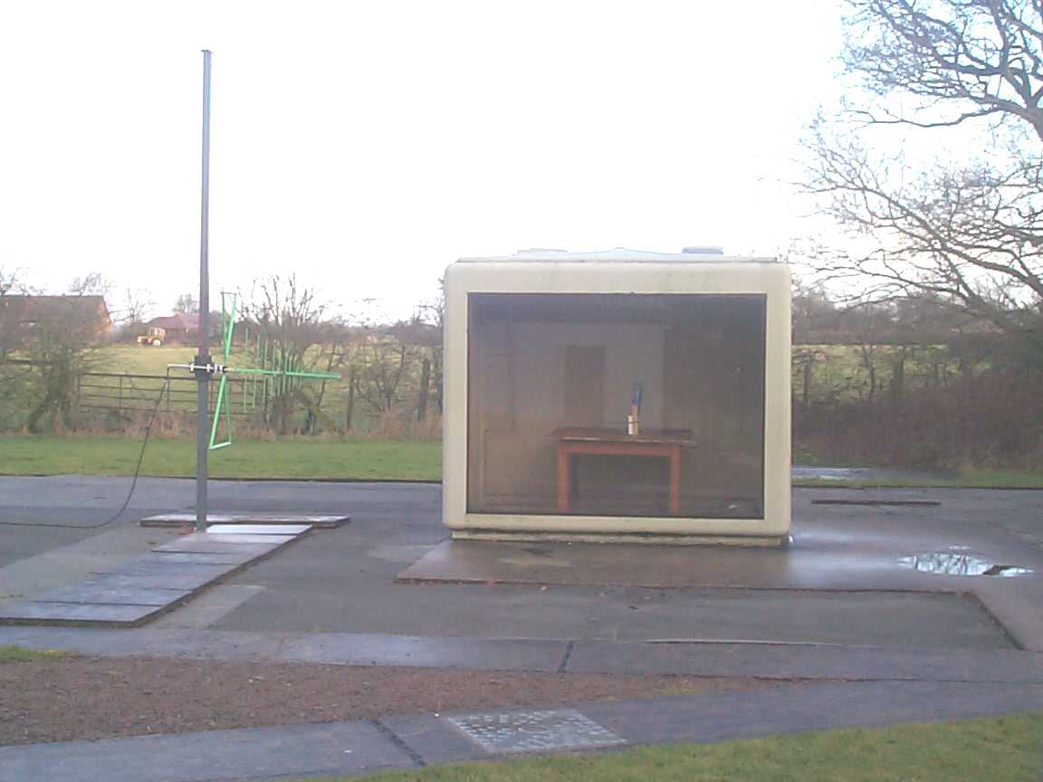
TRL COMPLIANCE SERVICES LTD EMC DIVISION LONG GREEN FORTHAMPTON GLOUCESTER GL19 4QH UNITED KINGDOM TELEPHONE +44 (0)1684 833818 FAX +44 (0)1684 833858 E- MAIL [email protected] www.trlcompliance.com 0728 TEST REPORT NO:RL1147/6611 COPY NO: ISSUE NO:1 FCC ID:MF3019174 REPORT ON THE CERTIFICATION TESTING OF A C A BLATCHFORD & SONS LTD ADAPTIVE LIMB WITH RESPECT TO THE FCC RULES CFR 47, PART 15.109, 15.209 & 15.249 INTENTIONAL RADIATOR SPECIFICATION TEST DATE: 21 st and 22 nd JANUARY 2002 TESTED BY:I FORSHAW APPROVED BY:S HAYES MANAGER EMC DIVISION DATE: Distribution: Copy Nos:1.C A BLATCHFORD & SONS LTD 2.FCC EVALUATION LABORATORIES 3.TRL EMC THIS DOCUMENT MAY BE REPRODUCED ONLY IN ITS ENTIRETY AND WITHOUT CHANGE RF335 iss01RL1147/6611Page 2 of 20 CONTENTS PAGE CERTIFICATE OF CONFORMITY & COMPLIANCE3 APPLICANT’S SUMMARY4 EQUIPMENT TEST / EXAMINATIONS REQUIRED5 TEST RESULTS / SAMPLE CALCULATIONS6-11 ANNEX PHOTOGRAPHSA PHOTOGRAPH No. 1: Test site with TX/RX PHOTOGRAPH No. 2: Equipment General View PHOTOGRAPH No. 3: TX/RX RF PCB track side PHOTOGRAPH No. 4: TX/RX RF PCB component side APPLICANT’S SUBMISSION OF DOCUMENTATION LISTB BAND OCCUPANCY PLOTC Notes: 1.Component failure during testYES NO [ ] [X] 2.If Yes, details of failure: 3.The facilities used for the testing of the product contained in this report are FCC Listed. 4.The contents of the attached applicants declarations and other supplied information are not covered by the scope of this laboratory’s UKAS or FCC accreditations’ and is provided in good faith. RF335 iss01RL1147/6611Page 3 of 20 CERTIFICATE OF CONFORMITY & COMPLIANCE FCC IDENTITY:MF3019174 PURPOSE OF TEST:FCC CERTIFICATION TEST SPECIFICATION:FCC RULES CFR 47, Part 15.109, 15.209 & 15.249 TEST RESULT:COMPLIANT TO SPECIFICATION EQUIPMENT UNDER TEST:ADAPTIVE LIMB EQUIPMENT SERIAL No:NOT APPLICABLE ITU: EMISSION CODE:75K0F1D EQUIPMENT TYPE:ADAPTIVE LIMB, REMOTE CONTROL TRANSCEIVER PRODUCT USE: DATA TRANSMISSION, TELEMETRY, TELECOMMAND OF AN ADAPTIVE LIMB CARRIER EMISSION: 18407.7μV/m @ 3 metres ANTENNA TYPE:FIXED ALTERNATIVE ANTENNA:NONE AS PER PART 15.203 BAND OF OPERATION: 914 MHz ±75kHz CHANNEL SPACING:NARROWBAND NUMBER OF CHANNELS:1 (ONE) FREQUENCY GENERATION:SAW Resonator[ ]Crystal [X]Synthesiser [ ] MODULATION METHOD:Amplitude[ ]Digital[X]Angle [ ] POWER SOURCE(s):+9V DC, INTEGRAL BATTERY TEST DATE(s):21 st AND 22 nd JANUARY 2002 ORDER No(s):PR39211 APPLICANT:C A BLATCHFORD & SONS LTD ADDRESS:LISTER ROAD BASINGSTOKE HAMPSHIRE G22 4AH TESTED BY:I FORSHAW APPROVED BY:S HAYES MANAGER EMC DIVISION RF335 iss01RL1147/6611Page 4 of 20 APPLICANT’S SUMMARY EQUIPMENT UNDER TEST (EUT):ADAPTIVE LIMB EQUIPMENT TYPE: ADAPTIVE LIMB, REMOTE CONTROL TRANSCEIVER SERIAL NUMBER OF EUT:NOT APPLICABLE PURPOSE OF TEST:FCC CERTIFICATION TEST SPECIFICATION(s):FCC RULES CFR 47, Part 15.109, 15.209 & 15.249 TEST RESULT:COMPLIANTYes No [X] [ ] APPLICANT’S CATEGORY:MANUFACTURER IMPORTER DISTRIBUTOR TEST HOUSE AGENT [X] [ ] [ ] [ ] [ ] APPLICANT’S ORDER No(s):PR39211 APPLICANT’S CONTACT PERSON(s):Mr ANDY SYKES E-mail address: [email protected] APPLICANT:C A BLATCHFORD & SONS LTD ADDRESS:LISTER ROAD BASINGSTOKE HAMPSHIRE G22 4AH TEL:+44 01256 316600 FAX:+44 01256 316711 EUT(s) COUNTRY OF ORIGIN:UNITED KINGDOM TEST LABORATORY:TRL EMC LTD UKAS ACCREDITATION No:0728 TEST DATE(s)21 st AND 22 nd JANUARY 2002 TEST REPORT No:RL1147/6611 RF335 iss01RL1147/6611Page 5 of 20 EQUIPMENT TEST / EXAMINATIONS REQUIRED 1. TEST/EXAMINATIONRULE PARTCOMMENTAPPLICABILITY Intentional Emission Frequency:15.249 Quasi – Peak Detector Applicable Intentional Emission Field Strength:15.249 Quasi – Peak Detector Applicable Intentional Emission Band Occupancy:15.249 Quasi – Peak Detector Applicable Spurious Emissions – Conducted 15.207Not ApplicableNot Applicable Receiver Spurious Emissions – Radiated :15.109 Quasi – Peak Detector Applicable Transmitter Spurious Emissions – Radiated :15.209 Quasi – Peak Detector Applicable Maximum Frequency of Search:15.33Up to 10 GHzApplicable Antenna Arrangements Integral:15.203 Antenna Permanently Attached Applicable Antenna Arrangements External Connector:15.204Not ApplicableNot Applicable Restricted Bands15.205FC 914MHz Not Applicable Extrapolation Factor15.31(f) 9.5dB from 1m-3m Applicable 2.Product Use:DATA TRANSMISSION, TELEMETRY, TELECOMMAND OF AN ADAPTIVE LIMB 3.Emission Designator:75K0F1D 4.Duty Cycle:23% 5.Transmitter bit or pulse rate:9600bps 6.Temperatures:Ambient (Tnom)(SEE TEST) 7.Supply Voltages:Vnom+9.0V DC Note: Vnom voltages are as stated above unless otherwise shown on the test report page Single channel[X] Two channel[ ] 8.Equipment Category: Multi-channel[ ] Narrowband[X] Wideband[ ] 9.Channel spacing: RF335 iss01RL1147/6611Page 6 of 20 RECEIVER TESTS RECEIVER SPURIOUS EMISSIONS – RADIATED – PART 15.109 Ambient temperature= 9 o C(<1GHz), 9°C (>1GHz) 3m measurements <1GHz[X] Relative humidity=68% (<1GHz), 68% (>1GHz)1m measurements >1GHz[X] Conditions=Open Area Test Site (OATS)3m extrapolated from 1m[ ] Supply voltage=Nom 12V Channel number=1 FREQ. (MHz) MEAS. Rx. (dBμV) CABLE LOSS (dB) ANT FACTOR FIELD STRENGTH (dBμV/m) EXTRAP. FACTOR (dB) FIELD STRENGTH (μV/m) 30MHz - 88MHzNO SIGNIFICANT EMISSION DETECTED 88MHz - 216MHz190.95 13.71.908.6024.2N/A16.2 216MHz - 960MHz625.87.404.3018.7030.4N/A33.1 960MHz -1GHzNO SIGNIFICANT EMISSION DETECTED 1GHz-10GHz1.82916.61.027.044.69.556.9 30MHz to 88MHz100μV/m @ 3m 88MHz to 216MHz150μV/m @ 3m 216MHz to 960MHz200μV/m @ 3m 960MHz to 1GHz500μV/m @ 3m Limits 1GHz to 10GHz500μV/m @ 3m Notes: 1Results quoted are extrapolated as indicated 2Emissions were searched to: 10GHz inclusive, as per Part 15.33a 3Extrapolation factor 9.5dB from 1m to 3m, as per Part 15.31f 4Measurements >1GHz @ 1m as per Part 15.31f(1) 5Receiver detector <1GHz = CISPR, Quasi-Peak, 120kHz bandwidth 6Receiver detector >1GHz = Peak Hold, 1MHz resolution bandwidth 7New batteries used for battery powered products. Test Method: 1As per Radio – Noise Emissions, ANSI …
Text truncated - open the document above for the full version.
Contact Information
Applicant
John J Shorter(Director)
Technical Contact
Chas. A. Blatchford & Sons LtdAndy J Sykes
[email protected]+44 1256 316689
Unit 6 · Basingstoke, Hampshire · United Kingdom
Non-Technical Contact
Chas. A. Blatchford & Sons LtdColin Edwards
[email protected]+44 1256 316657
Test Firm
TRL EMC LimitedNeil Roche
Technical Specifications
| # | Rule Parts | Frequency Range | Power Output | Emission | Tolerance |
|---|---|---|---|---|---|
| 1 | 15C | 914.13 MHz - 914.9 MHz | 100.00 µW | 75K0F1D | 55.0000000000 ppm |
Other Applications from Chas A Blatchford & Sons Ltd
MF3019173U
Apr 04, 2002Communications module-Artificial Limb
Equipment Class
DSR - Part 15 Remote Control/Security Device TransceiverMF3239129
Feb 28, 1996Prothesis Controller Receiver
Equipment Class
CYY - Communications Receiver used w/Pt 15 TransmitterMF3019142
Nov 06, 1995Prothesis Controller
Equipment Class
DXX - Part 15 Low Power Communication Device Transmitter