MHASOHOIFAAnimal implantable telemetry for medically related applications in laboratory environments.
Data Sciences International, an affiliate of Harvard Bioscience, Inc.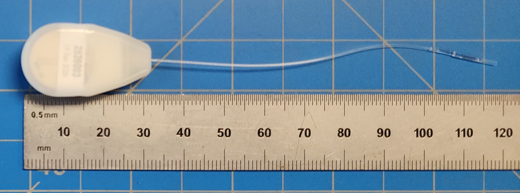
Click to zoom
Application Details
- Equipment Class
- DXX - Part 15 Low Power Communication Device Transmitter
- Date of Grant
- Aug 27, 2026
- Application Purpose
- Original Equipment
- Equipment Note
- Animal implantable telemetry for medically related applications in laboratory environments.
- Frequency Range
- 2402.00000000 - 2480.00000000
- Country
- United States
Documents & Files
Document Text
Text extracted from the exhibit documents filed with the FCC. Open a document above to read the original.
Users Manual
Page 111 DSI Implantable Telemetry • Publication 012527-001 REV 03 • www.datasci.com ©2026 Data Sciences International Note: The Frequency in the CLC Details page will display the last Frequency selected in the Search for Implants dialog (e.g. F1-B1). Once the implants change to their new frequency (e.g. F1-D1), the CLC Details Frequency will reflect its originally selected Frequency (F1-D1) 10. The CLC Configuration List View will update with the implants, along with the Configured Implants list within the CLC Details. 11. Repeat steps 6-10 for any additional CLCs/implants. Page 112 DSI Implantable Telemetry • Publication 012527-001 REV 03 • www.datasci.com ©2026 Data Sciences International 12. Once complete, click the Save & Exit button. Page 113 DSI Implantable Telemetry • Publication 012527-001 REV 03 • www.datasci.com ©2026 Data Sciences International PhysioTel Digital Configuration Details Multiple layers of information are contained in the PhysioTel Digital Hardware Configuration dialog, each accessed using the List View on the left side. The CLC Configuration column lists the entire setup in an expandable tree structure. The CLCs are listed with their assigned implants nested underneath. Note: The tree structure can be expanded and contracted by clicking on the arrows immediately to the left of the individual line items. Hover the mouse cursor over any line item in the Configuration box to activate an information pop-up with that device’s key status condition. The example below is the hover information for a CLC. Page 114 DSI Implantable Telemetry • Publication 012527-001 REV 03 • www.datasci.com ©2026 Data Sciences International The CLC Configuration is the first line in the List View and displays the Selected CLC for the current configuration. The List View can also be used to access the following information: • CLC Details • Implant Details • Channel Details CLC Details The CLC Details view can be accessed by left-clicking on any of the CLC line items in the List View. Page 115 DSI Implantable Telemetry • Publication 012527-001 REV 03 • www.datasci.com ©2026 Data Sciences International Page 116 DSI Implantable Telemetry • Publication 012527-001 REV 03 • www.datasci.com ©2026 Data Sciences International CLC Details include: CLC Fields Description A. CLC Name: Select the Set CLC Name... button to create or change the name of the CLC. This name is saved on the CLC and will be the name seen when searching the network for available CLCs to add to the configuration with the PhysioTel Digital Configuration. B. About: Important information including CLC model and serial numbers, current frequency, IP Address, and Firmware. This same information is available by hovering the mouse cursor over the line item in the List View. C. Frequency Dropdown box used to select the frequency of the CLC. D. Enable TRX(s) Checkbox used to enable (checked) and disable (unchecked) the CLC broadcast frequency. Disabling the TRXs may be useful in preventing the CLC from interfering with the implant configuration process of another CLC in the configuration or on the network. E. Configured Implants Lists the implants currently configured to this CLC. F. Search for Implants... Allows the user to search for implants that are powered ON and in range for assignment to the CLC within this configuration. G. Remove Implants Allows the user to select the implants from the Configured Implants list and remove them from the configuration. H. TRXs: List of TRXs and serial numbers assigned to that CLC and the “Jack” number on the back panel of the CLC the TRX is plugged into. Page 117 DSI Implantable Telemetry • Publication 012527-001 REV 03 • www.datasci.com ©2026 Data Sciences International CLC Fields Description I. Information Provides the user with instructions on actions to perform on that Details page. Implant Details The Implant Details can be accessed by left-clicking on any of the implant names in the List View. The Implant Details view contains implant information, as well as some important interactive features. Implant Details contains the following information: Page 118 DSI Implantable Telemetry • Publication 012527-001 REV 03 • www.datasci.com ©2026 Data Sciences International Implant Details Field Description A. Implant Name: User may rename the implant by selecting the Set Implant Name... button. In the displayed dialog, enter the desired name in the text field and select OK. Upon selecting OK, a will display next to the existing implant name while the CLC communicates the name to the Implant. Once the implant is programmed with the name, the dialog will close. The name specified here is also used by Ponemah as the Subject Name when automatically creating the Subject upon clicking Save & Exit within this dialog. B. Enabled: This check box will toggle the implant between ‘Enabled’ and ‘Disabled’ modes. The Enabled mode allows the software system to record, store, and analyze data from the implant. WARNING: if the implant is not Enabled, the implant will still be powered ON and in communication with the system, but no data from the implant will be acquired. C. About: Important information including model and serial numbers, activation and manufacture dates, as well as a battery level indicator. This same information is available by hovering the mouse cursor over the line item in the List View. Page 119 DSI Implantable Telemetry • Publication 012527-001 REV 03 • www.datasci.com ©2026 Data Sciences International Implant Details Field Description D. Active Channels E. Inactive Channels These columns allow the user to select which data collection channels are activated in the implant. Active Implant Channels collect physiologic data and transmit the data through the acquisition system to be stored in the data acquisition computer. Inactive Channels do not collect physiologic data as those channels are disabled. Note: In addition to avoiding the collection of unnecessary data, the in-activation of certain data ch…
Text truncated - open the document above for the full version.
Users Manual
Publication #012527-001 Rev #03 DSI Implantable Telemetry System Manual USER MANUAL Page 2 DSI Implantable Telemetry • Publication 012527-001 REV 03 • www.datasci.com ©2026 Data Sciences International Table of Contents Compliance Statement .................................................................................................................................................. 5 ISED RSS-Gen Notice ................................................................................................................................................. 5 2.4GHz General-purpose Micro power (Short Distance) Radio Equipment .............................................................. 5 SoHo Implants ........................................................................................................................................................... 7 Supporting Hardware ................................................................................................................................................ 8 Welcome ........................................................................................................................................................................ 9 What You Will Be Learning ........................................................................................................................................ 9 PhysioTel HD and PhysioTel Legacy Telemetry Platform Manual ............................................................................... 10 System Overview ..................................................................................................................................................... 10 About the Implants ................................................................................................................................................. 12 PhysioTel Hybrid Digital (HD) .............................................................................................................................. 12 PhysioTel Legacy ................................................................................................................................................. 15 Implant Components .......................................................................................................................................... 16 Understanding Activity Measurements .............................................................................................................. 20 Understanding Specifications .................................................................................................................................. 22 Animal Implantation Recommendations ............................................................................................................ 22 Device Warranty ................................................................................................................................................. 22 Pressure Specifications ....................................................................................................................................... 22 Battery Life .......................................................................................................................................................... 23 Instructions for Implant Operation ......................................................................................................................... 24 PhysioTel Digital Telemetry Platform Manual ............................................................................................................. 26 System Overview ..................................................................................................................................................... 26 About the Implants ................................................................................................................................................. 26 PhysioTel Digital Features ................................................................................................................................... 26 Nomenclature ..................................................................................................................................................... 27 Implant Components .......................................................................................................................................... 29 Understanding Activity Measurements .............................................................................................................. 36 Broadcasting Frequencies ....................................................................................................................................... 37 Instructions for Implant Operation ......................................................................................................................... 38 Implant Operation Modes .................................................................................................................................. 38 Implant Activation............................................................................................................................................... 40 Page 3 DSI Implantable Telemetry • Publication 012527-001 REV 03 • www.datasci.com ©2026 Data Sciences International Implant Deactivation........................................................................................................................................... 41 SoHo Telemetry Platform Manual ............................................................................................................................... 45 System Overview ..................................................................................................................................................... 45 About the Implants ..................................................................................................................................…
Text truncated - open the document above for the full version.
Attestation Statements
Harvard Bioscience, Inc. A Life Sciences Company 84 October Hill Rd, Suite 10 • Holliston, MA 01746 U.S.A. Phone: +1 508 893 8999 • Fax: +1 508 429 5732 Date: 08-05-2026 To: Federal Communications Commission Authorization and Evaluation Division 7435 Oakland Mills Road Columbia, MD 21046 USA Ref: Attestation Statements Part 2.911(d)(5)(i) and Part 2.911(d)(5)(ii) Filing Re. KDB 986446 D01 FCC ID: MHASOHOIFA Dear Sir or Madam, Data Sciences International an affiliate of Harvard Bioscience Inc, certifies that the equipment for which authorization is sought is not “covered” equipment prohibited from receiving an equipment authorization pursuant to section 2.903 of the FCC rules. We also certify that, as of the date of the filing of the application, the applicant is not identified on the Covered List as an entity producing “covered” equipment. We further attest that the equipment for which authorization is sought does not contain integrated Kaspersky cybersecurity and/or anti-virus software produced by Kaspersky Lab Inc. or any of its successors and assignees. If you have any questions, please contact us. Sincerely, Contact name: Matt Kunz Company name: Data Sciences International an affiliate of Harvard Bioscience Inc. Address: 119 14th Street NW Suite 100, St. Paul, MN 55112 E-mail: [email protected] Tel: 651-414-5410
Attestation Statements
Harvard Bioscience, Inc. A Life Sciences Company 84 October Hill Rd, Suite 10 • Holliston, MA 01746 U.S.A. Phone: +1 508 893 8999 • Fax: +1 508 429 5732 To: Federal Communications Commission Authorization and Evaluation Division 7435 Oakland Mills Road Columbia, MD 21046 USA Date: 08-27-2026 Ref: Attestation Statements Part 2.911(d)(7) Filing FCC ID: MHASOHOIFA Data Sciences International, an affiliate of Harvard Bioscience Inc. (“the applicant”) certifies that, as of the date of the filing of the application, Data Sciences International, an affiliate of Harvard Bioscience Inc. is our designated U.S. agent for service of process for the above referenced FCC ID. Data Sciences International, an affiliate of Harvard Bioscience Inc., accepts to maintain an agent for no less than one year after the grantee has terminated all marketing and importation or the conclusion of any Commission-related proceeding involving the equipment. Data Sciences International, an affiliate of Harvard Bioscience Inc. accepts, as of the date of the filing of the application, the obligation of the designated U.S. agent for service of process for the above referenced FCC ID. Designated U.S. Agent Information: Name: Data Sciences International, an affiliate of Harvard Bioscience Inc. Address: 119 14th Street NW Suite 100 St. Paul, MN 55112 Contact Person: Matt Kunz Tel.: 651-414-5410 Email: [email protected] FRN: 0015401920 Sincerely, [Insert U.S. agent company name] DSI an affiliate of Harvard Bioscience, Inc. (U.S. agent company name printed name) Matt Kunz (U.S. agent company name signature) [Insert applicant name] DSI an affiliate of Harvard Bioscience, Inc. (Applicant printed name) Matt Kunz (Applicant signature)
Cover Letter(s)
Harvard Bioscience, Inc. A Life Sciences Company 84 October Hill Rd, Suite 10 • Holliston, MA 01746 U.S.A. Phone: +1 508 893 8999 • Fax: +1 508 429 5732 Date (08/05/2026) TUV SUD America Inc. 401 Edgewater Drive Ste 500 Wakefield MA 01880 Dear Sir or Madam, We, Data Sciences International an affiliate of Harvard Bioscience Inc., located at address: 119 14th Street NW Suite 100, St. Paul, MN 55112, hereby authorize Rossana Sarai of TUV SUD America, 5945 Cabot Parkway, Alpharetta, GA 30005 and Matt Kunz of Data Sciences Intl. to act as our agent in all matters relating to applications for equipment authorization, including the signing of all documents relating to these matters. Yours sincerely, Name: Matt Kunz Title: Senior Principal Electrical Engineer
Cover Letter(s)
Harvard Bioscience, Inc. A Life Sciences Company 84 October Hill Rd, Suite 10 • Holliston, MA 01746 U.S.A. Phone: +1 508 893 8999 • Fax: +1 508 429 5732 Date (08/05/2026) Certification and Engineering Bureau Innovation, Science and Economic Development Canada P.O. Box 11490, Station H 3701 Carling Avenue (Building 94) Ottawa, Ontario K2H 8S2 Confidentiality Request IC: 5681A-SOHOIFA Pursuant to RSP-100 Paragraph 9.4, we, Data Sciences International an affiliate of Harvard Bioscience Inc., hereby requests confidential treatment of information accompanying this application as outlined below: Schematics, Block Diagram, Theory of Operation, Parts List The above materials contain trade secrets and proprietary information not customarily released to the public. The public disclosure of these matters might be harmful to the Applicant and provide unjustified benefits to its competitors. We, Data Sciences International Inc., an affiliate of Harvard Biosciences, hereby authorize TUV SUD America and Innovation, Science and Economic Development Canada to publish all or part of the following information on the IC website: Certification number; Company number; previous certification number (if applicable); Company name; Company contact information (name, address, email, fax, phone; Manufacturer (name, contact person address, email, fax, phone; Representative in Canada; Model name and/or number as it appears on the product; Specification or standard code and issue number; Type of equipment (equipment category); Test Lab name, address, ID #, OATS filing reference number; Test Lab report number and date; List of accessories with which the equipment was tested; List of operational features; Frequency Range; Emission Designator(s); (Nature of signal(s); Type of information being transmitted; Details about the signal(s); Nature of multiplexing ;) Bandwidth(s); Type of modulation(s); Field strength measured in microvolt per meter @ 3 meters if the antenna is integral to the device or conducted RF Power if the antenna is detachable; and Gain of antenna(s) the device was certified with. Yours sincerely, Name: Matt Kunz Title: Senior Principal Electrical Engineer
Cover Letter(s)
Data Sciences International, an affiliate of Harvard Bioscience, Inc. Family of models for SoHo pressure implants The only difference between the two models is the size. The PCBA is identical but SoHo- S10 utilizes larger batteries, such that the life of the implant’s function can be extended for larger species. Same PCBA for both models Model# No. of Catheters Battery Size Vol (CC) Package SoHo-X10 1 SR916SW 1.2 SoHo-S10 1 CR1632 4.4
RF Exposure Info
TÜV SÜD AMERICA INC 10040 Mesa Rim Road San Diego, CA 92121-2912 Phone: 858 678 1400 FAX: 858 546 0364 August 24, 2026 TUV SUD America CB 401 Edgewater Place Suite 500 Wakefield, MA 01880 Attention: Director of Certification RE: Analysis of RF Exposure for Portable and Mobile use per CFR Title 47 Chapter I Subchapter A §1.1307(b)(3)(i)(A) and RSS-102 Issue 6 December 15, 2023 FCC ID: MHASOHOIFA ISED Certification Number: 5681A-SOHOIFA General Information: Applicant: Data Sciences International, an affiliate of Harvard Bioscience Inc. Environment: General Population/Uncontrolled Exposure Exposure Conditions: Portable Technical Information: Minimum Test Separation Distance: 5 mm Highest Operating Frequency: 2480 MHz Antenna Type: PCB Inverted F Antenna Gain: -13.56 dBi Maximum Transmitter EIRP: -20.88 dBm, 0.01 mW Peak-worst case The EUT is exempt from routine evaluation per the 1 mW Blanket Exemption of §1.1307(b)(3)(i)(A) having a maximum transmitter EIRP of 0.01 mW. Guidance is from Section 2.1.1 and 2.1.2 of KDB447498 D04. The EUT also complies with RSS-102 Exemption Limits for Routine SAR Evaluation per Section 6.3 and Table 11. 1mW is also used as exemption threshold (worst case) which typically applies to implanted medical devices. Sincerely, Joe Salvador Name Authorized Signatory Title: Wireless Test Engineer
Test Report
Document Number: 721022563B- Issue 01 | Version Number: 01 COMMERCIAL-IN-CONFIDENCE COMMERCIAL-IN-CONFIDENCE Page 1 of 63 RESPONSIBLE FOR NAME DATE SIGNATURE Project Management Joe Salvador 24-Aug-2026 Authorised Signatory Ferdinand Custodio 24-Aug-2026 Signatures in this approval box have checked this document in line with the requirements of TÜV SÜD Product Service document control rules. EXECUTIVE SUMMARY A sample of this product was tested and found to be in compliance with FCC 47 CFR Part 15.249 and ISED RSS-210. Radio Testing of the Data Sciences International Models: SoHo - X10, SoHo - S10 In accordance with FCC 47 CFR Part 15.249 and ISED RSS-210 Prepared for: Data Sciences International 119 14th St NW Suite 100 St. Paul, MN 55112 COMMERCIAL-IN-CONFIDENCE Date: 24-Aug-2026 Document Number: 721022563B Issue 01 | Version Number: 01 A2LA Cert. No. 2955.13 DISCLAIMER AND COPYRIGHT This report has been prepared by TÜV SÜD America with all reasonable skill and care. The document is confidential to the potential Client and TÜV SÜD America. No part of this document may be reproduced without the prior written approval of TÜV SÜD America. © 2019 TÜV SÜD America ACCREDIATION Our A2LA Accreditation does not cover opinions and interpretations and any expressed are outside the scope of our A2LA Accreditation. Document Number: 721022563B- Issue 01 | Version Number: 01 COMMERCIAL-IN-CONFIDENCE COMMERCIAL-IN-CONFIDENCE Page 2 of 63 Contents 1 Report Summary ..................................................................................................................... 3 1.1 Report Modification Record ....................................................................................................... 3 1.2 Introduction ............................................................................................................................... 3 1.3 Brief Summary of Results.......................................................................................................... 4 1.4 Product Information ................................................................................................................... 5 1.5 Deviations from the Standard .................................................................................................... 7 1.6 EUT Modification Record .......................................................................................................... 7 1.7 Test Location ............................................................................................................................ 7 2 Test Details .............................................................................................................................. 8 2.1 AC Power Line Conducted Emissions ....................................................................................... 8 2.2 20 dB Bandwidth and 99% Emission Bandwidth ...................................................................... 9 2.3 Field Strength of Fundamental .................................................................................................18 2.4 Field Strength of Emissions ......................................................................................................27 2.5 Antenna Requirement ..............................................................................................................59 3 Test Equipment Information ..................................................................................................60 3.1 General Test Equipment Used .................................................................................................60 3.2 Customer Support Equipment ..................................................................................................60 4 Incident Reports .....................................................................................................................61 5 Photographs ...........................................................................................................................62 5.1 Equipment Under Test (EUT) ...................................................................................................62 6 Measurement Uncertainty .....................................................................................................63 Document Number: 721022563B- Issue 01 | Version Number: 01 COMMERCIAL-IN-CONFIDENCE COMMERCIAL-IN-CONFIDENCE Page 3 of 63 1 Report Summary 1.1 Report Modification Record Alterations and additions to this report will be issued to the holders of each copy in the form of a complete document. Issue Description of Change Date of Issue 1 First Issue 24-Aug-2026 Table 1 1.2 Introduction Applicant Data Sciences International Manufacturer Data Sciences International Model Number(s) SoHo-X10, SoHo-S10 (Only model SoHo-X10 was tested. See Family of models- X10.pdf) Serial Number(s) 1364280, 1364279 (Conducted Samples) 1365576,1365583 (Radiated Samples) Hardware Version(s) PCBA- Rev04C Software Version(s) Firmware: 2.6174 – Implants FCC ID MHASOHOIFA IC Number 5681A-SOHOIFA Manufacturer’s declared output power 1mW (0 dBm) Test Specification/Issue/Date FCC 47 CFR Part 15.249, ISED RSS-210 and ISED RSS- GEN Issue 2 (February 23, 2024) Test Plan/Issue/Date WirelessTest_Instructions-Rev05.pdf Order Number Date 200210020446 09-July-2026 Date of Receipt of EUT 09-July-2026 Start of Test 10-July-2026 Finish of Test 20-July-2026 Name of Engineer(s) Joe Salvador Related Document(s) • X10 IFA Antenna Datasheet.pdf Document Number: 721022563B- Issue 01 | Version Number: 01 COMMERCIAL-IN-CONFIDENCE COMMERCIAL-IN-CONFIDENCE Page 4 of 63 • Family of models – X10.pdf • ANSI C63.10-2020 1.3 Brief Summary of Results A brief summary of the tests carried out in accordance with FCC 47 CFR Part 15C and ISED RSS- 210 and ISED RSS-GEN is shown below. Section Specification Clause Test Description Result Comments Bluetooth Low Energy – 1Mbps, 2Mbps - TX Mode 2.1 15.207, and 8.8 AC Power Line Conduc…
Text truncated - open the document above for the full version.
Test Report
SoHo-X10/S10 IFA Antenna Datasheet Frequency2440MHz Average Gain-16.17dB Peak Gain-13.56dBi Efficiency2.41% The SoHo-X10/S10 PCB Trace Inverted “F” Antenna (IFA) is an antenna structure fabricated onto the implant’s PCB. The device under test (DUT) was performed in Speag broad band solution to emulate tissue with a wall depth of 2mm. The antenna is designed and tuned for implantation. Data represented at 2440MHz, highest gain between 2400-2480MHz RF Spectrum. Data Sciences International, an affiliate of Harvard Biosciences Inc. 10mm Antenna Location 2D Polar Plots
Test Setup Photos
Manufacturer Part Number: Data Sciences International, an affiliate of Harvard Bioscience Inc. EUT Description: Implant FCC ID: MHASOHOIFA IC: 5681A-SOHOIFA Model: SoHo-X10, SoHo-S10 TÜV SÜD America, Inc., 10040 Mesa Rim Road, San Diego, CA 92121-2912 Test Setup Photos Exhibit Page 1 of 6 Radiated Emissions Test Setup (9kHz to 30MHz) Manufacturer Part Number: Data Sciences International, an affiliate of Harvard Bioscience Inc. EUT Description: Implant FCC ID: MHASOHOIFA IC: 5681A-SOHOIFA Model: SoHo-X10, SoHo-S10 TÜV SÜD America, Inc., 10040 Mesa Rim Road, San Diego, CA 92121-2912 Test Setup Photos Exhibit Page 2 of 6 Radiated Emissions Test Setup (30MHz to 1GHz) Manufacturer Part Number: Data Sciences International, an affiliate of Harvard Bioscience Inc. EUT Description: Implant FCC ID: MHASOHOIFA IC: 5681A-SOHOIFA Model: SoHo-X10, SoHo-S10 TÜV SÜD America, Inc., 10040 Mesa Rim Road, San Diego, CA 92121-2912 Test Setup Photos Exhibit Page 3 of 6 Radiated Emissions Test Setup (1GHz to 8GHz) Manufacturer Part Number: Data Sciences International, an affiliate of Harvard Bioscience Inc. EUT Description: Implant FCC ID: MHASOHOIFA IC: 5681A-SOHOIFA Model: SoHo-X10, SoHo-S10 TÜV SÜD America, Inc., 10040 Mesa Rim Road, San Diego, CA 92121-2912 Test Setup Photos Exhibit Page 4 of 6 Radiated Emissions Test Setup (8GHz to 18GHz) Manufacturer Part Number: Data Sciences International, an affiliate of Harvard Bioscience Inc. EUT Description: Implant FCC ID: MHASOHOIFA IC: 5681A-SOHOIFA Model: SoHo-X10, SoHo-S10 TÜV SÜD America, Inc., 10040 Mesa Rim Road, San Diego, CA 92121-2912 Test Setup Photos Exhibit Page 5 of 6 Radiated Emissions Test Setup (18GHz to 26GHz) Manufacturer Part Number: Data Sciences International, an affiliate of Harvard Bioscience Inc. EUT Description: Implant FCC ID: MHASOHOIFA IC: 5681A-SOHOIFA Model: SoHo-X10, SoHo-S10 TÜV SÜD America, Inc., 10040 Mesa Rim Road, San Diego, CA 92121-2912 Test Setup Photos Exhibit Page 6 of 6 Conducted Test Set Up
Contact Information
Applicant
Matt Kunz(Senior Principal Electrical Engineer)
[email protected]Fax: (651)481-7417
Technical Contact
Data Sciences International, an affiliate of HarvaMatt Kunz
119 14th Street NW · St. Paul, Minnesota, 55112 · United States
Test Firm
TUV SUD America Inc.Mac Elliott
[email protected]Fax: 978 977 0182
Technical Specifications
| # | Rule Parts | Frequency Range | Power Output |
|---|---|---|---|
| 1 | 15C | 2.40 GHz - 2.48 GHz | - |
Other Applications from Data Sciences International, an affiliate of Harvard Bioscience, Inc.
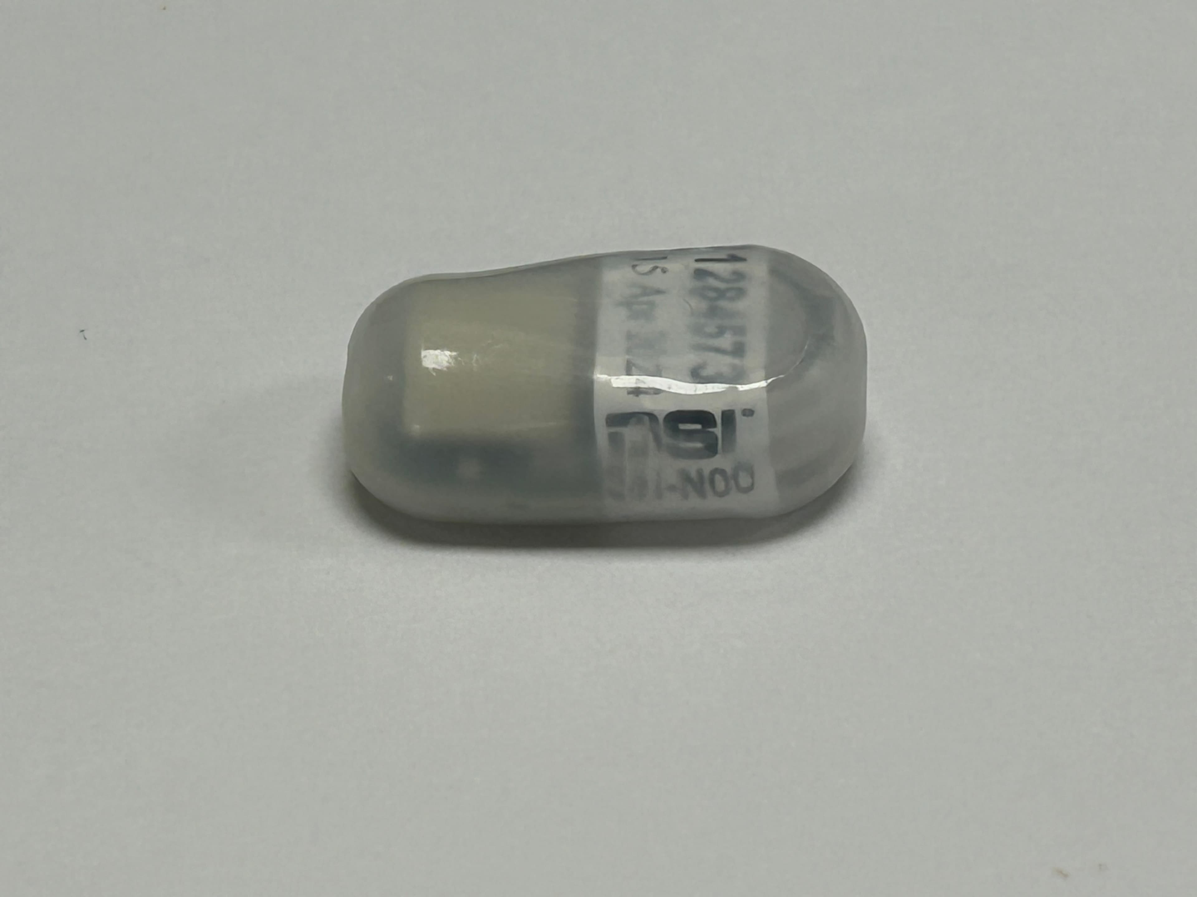
MHASOHO
Jul 07, 2024Animal implantable telemetry for medically related applications in laboratory environments.
Equipment Class
DXX - Part 15 Low Power Communication Device Transmitter
MHAHD18
Sep 22, 2015Small Animal Implant Transmitter
Equipment Class
DXX - Part 15 Low Power Communication Device Transmitter
MHAPTDM1
Aug 14, 2014Digital Animal Implant Transceiver for use in Medical Research Laboratory Environments
Equipment Class
DXX - Part 15 Low Power Communication Device Transmitter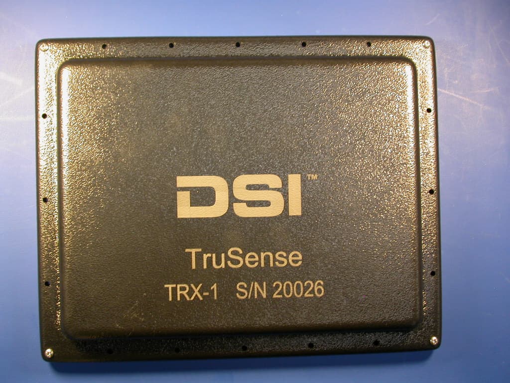
MHATRUTRX
Jun 28, 2012Transceiver used to collect data from multiple devices implanted in animals used for scientific study
Equipment Class
DXX - Part 15 Low Power Communication Device Transmitter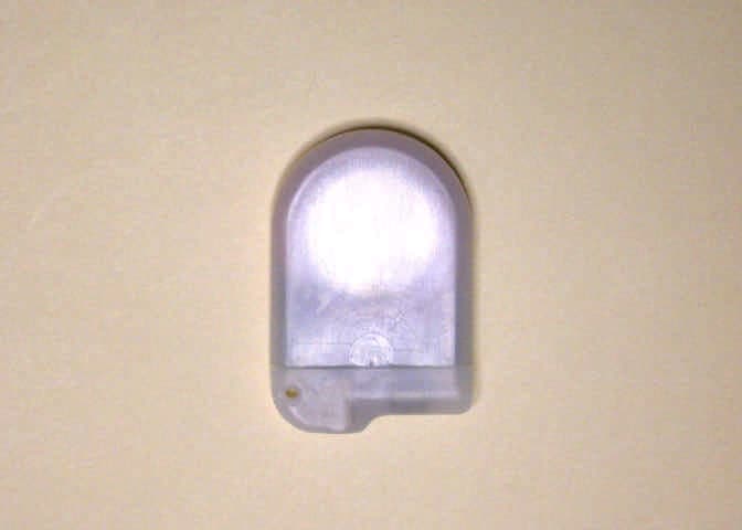
MHATMS1
Dec 05, 2006Small Animal Implant Transmitter
Equipment Class
DXX - Part 15 Low Power Communication Device Transmitter