MHSVM105Master Base Unit VM105
ADcom Information Services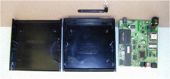
Click to zoom
Application Details
- Equipment Class
- DXX - Part 15 Low Power Communication Device Transmitter
- Date of Grant
- Apr 09, 2002
- Application Purpose
- Original Equipment
- Date of Application
- Apr 09, 2002
- Equipment Note
- Master Base Unit VM105
- Frequency Range
- 916.48000000 - 916.48000000
- Company
- ADcom Information Services
- Country
- United States
Documents & Files
Document Text
Text extracted from the exhibit documents filed with the FCC. Open a document above to read the original.
Users Manual
MBU Installation Manual p/n 10204 Scope. The MBU (p/n 10182) is part of the VM105 television viewership metering system. Along with the SSU (p/n 10179), the system monitors and records the time of day and channels viewed by household television sets. A typical installation will use only one MBU, and as many SSU’s as there are television sets. Installation. Determine Install Site. The MBU is preferably installed in an out of the way location. This helps insure that it will not be accidentally (or intentionally!) unplugged or bothered. The only requirements for the install site are that an AC power source and a telephone line be present. Closets, under beds, sofas, or dressers, or in the rafters in basements are all generally good locations. Use your judgement in each case. Make sure that the power source is not switched on or off with a wall switch. Telephone line may need to be run to the ‘hiding’ place. In these cases, make the telephone line install as unobtrusive as possible. If possible, the location should also be central to all SSU’s. This is to minimize the maximum length for the RF link to traverse. Connect Power Supply. The MBU uses a 5 watt ‘wall wart’ power supply, rated at 9VDC at 500mA. Connect this to an unused outlet. If none is available, add an extension cord or power strip to the setup. The power supply should be secured through the use of nylon tie wraps to the power strip or extension cord. If available, use a screw down clip for attaching the power supply to an outlet. Connect the output of the power supply to the MBU. Run TechCom Install Software. Connect your communications cable from your palm top computer to the MBU. Run the TechCom software, which will allow you to configure the setup for the different SSU’s. Do not connect the phone line at this time! After running through the required setup menus, finish installing the SSU’s before continuing with data collection. Data Collection. After the SSU’s have been installed and tested, but before the acquisition tests, return to the MBU and use your palm top to force an End Of Data Day, (EODD) to allow the MBU to contact each of the SSU’s via the RF link. This will update the clocks in each SSU. Next erase all viewship data collected thus far. Now, run your acquisition tests for each SSU. After the tests, force another EODD. This will collect the acquisition test data for downloading to the collection system. Enter Household Data. After the SSU’s have reported their acquisition test data, enter all other pertinent household data into the MBU, using the TechCom menu driven prompts. Call in Data. After all the data has been entered, connect the phone line to the MBU. Using the palm top software, force a call to the collection system. During the first 10 seconds of the call, test the automatic off-hook circuits by lifting one of the household’s phones off hook. Observe that the MBU immediately hangs up the line. Next, force the MBU to re-call and deliver its data. Verify Data Collection. After the MBU has finished tranfering its data and hangs up the phone, verify that the MBU viewership data has been erased. This indicates that data was successfully transferred to the collection system. Dress Wires. After testing the MBU is complete, dress up the wires going to the MBU. Leave no dangling or unsecured lengths of wire which could easily be grasped and pulled on. Tuck the MBU into its hiding place, and insure that the power and phone line connections are still secure. The goal here is to make the installation as invisible as possible. The MBU and\or its wires should not be seen by the casual observer. End of Install
External Photos
TOP UNIT OPEN UNIT OPEN WITH BOARD IN END AND BOTTOM END AND SIDE
Internal Photos
BOARD BACK BOARD TOP BOARD TOP BOARD TOP BOARD TOP BOARD TOP BOARD TOP
Test Report
TÜV PRODUCT SERVICE 10040 Mesa Rim Road San Diego, CA 92121-2912 Phone 858 546 3999 FAX 858 546 0364 Report No. 201089-08 Page 1 of 18 Rev.No 1.0 MEASUREMENT AND TECHNICAL REPORT ADCOM INFORMATION SERVICES, INC. 700 West Hillsboro Boulevard Deerfield Beach, FL 33441 DATE: 25 March 2002 This Report Concerns: Original Grant: X Class II Change: Equipment Type: VM105, Master Base Unit (MBU), Model 10182 Deferred grant requested per 47 CFR 0.457(d)(1)(ii)? Yes: Defer until: No: X Company Name agrees to notify the Commission by: N/A of the intended date of announcement of the product so that the grant can be issued on that date. Transition Rules Request per 15.37? Yes: *No: X (*) FCC Part 15, Paragraphs 15.207(a); 15.109(a); 15.249 Report Prepared by: TÜV PRODUCT SERVICE 10040 Mesa Rim Road San Diego, CA 92121-2912 Phone: 858 546 3999 Fax: 858 546 0364 TÜV PRODUCT SERVICE 10040 Mesa Rim Road San Diego, CA 92121-2912 Phone 858 546 3999 FAX 858 546 0364 Report No. 201089-08 Page 2 of 18 Rev.No 1.0 TABLE OF CONTENTS Pages 1 GENERAL INFORMATION 1.1 Product Description 1.2 Related Submittal Grant 1.3 Tested System Details 1.4 Test Methodology 1.5 Test Facility 2 SYSTEM TEST CONFIGURATION 2.1 Justification 2.2 EUT Exercise Software 2.3 Special Accessories 2.4 Equipment Modifications 2.5 Configuration of Tested System 3 RADIATED EMISSION EQUIPMENT/DATA Field Strength Calculation 4 CONDUCTED EMISSION EQUIPMENT/DATA 5 Attestation Statement TÜV PRODUCT SERVICE 10040 Mesa Rim Road San Diego, CA 92121-2912 Phone 858 546 3999 FAX 858 546 0364 Report No. 201089-08 Page 3 of 18 Rev.No 1.0 1 GENERAL INFORMATION 1.1 Product Description NAME, MODEL OF EUT: VM105, Master Base Unit (MBU), Model 10182 POWE4 REQUIREMENTS: 120 Vac, 1 Phase, 0.1 A; uses 9 Vdc @.5A wall transformer TYPICAL INSTALLATION: Home EUT POWER CABLE: Removable, unshielded 2 meters EUT INTERFACE PORTS & CABLES: RS232, 1; digital; shielded; foil; Termination: Dsub-9; Connector type: mini-DIN4; Port termination: None; 1 m; removable RJ112, 1; Analog; not shielded; Connector type: RJ11; Port termination: 600 Ohm; 2 m; removable Power, 1; analog; not shielded; Connector type: 5.5 x 2.1 power jack; 2 m OPERATING MODE: Data transmit mode; data receive mode & modem active EUT SYSTEM COMPONENTS: Power Supply, Model Jame Co DC905F12 SUPPORT EQUIPMENT: Phone line simulator OSCILLATOR FREQUENCIES: 11.0592 MHz; Location: U3, crystal osc.; Description of use: micro oscillator 16 MHz; Location: U12, socket modem module; Description of use: micro oscillator 32.768 MHz; Location: U7, real time clock crystal osc.; Description of use: clock chip POWER SUPPLY: Jame Co, Model DC905F12, Linear POWER LINE FILTERS: N/A EMC CRITICAL DETAIL: Antenna, Linx Technologies, 916 MHz, ¼ wave whip Transceiver, Linx Technologies, Model TR-916-SC TÜV PRODUCT SERVICE 10040 Mesa Rim Road San Diego, CA 92121-2912 Phone 858 546 3999 FAX 858 546 0364 Report No. 201089-08 Page 4 of 18 Rev.No 1.0 1 GENERAL INFORMATION (continued) 1.2 Related Submittal/Grant None 1.3 Tested System Details The FCC IDs for all equipment, plus descriptions of all cables used in the tested system are: None 1.4 Test Methodology Purpose of Test: To demonstrate compliance with the ANSI C63.4 setup. TEST FCC CFR 47 # PASS/FAIL Radiated Conducted Emissions 15.109(a); 15.249 15.107(a) Pass Pass Test Performed: X 1. Conducted Emissions, FCC Part 15, 15.107(a) 2. Radiated Emissions EN55022: 1992 Class B limit, 30 - 1,000 MHz, 10 meters X 3. Radiated Emission per FCC Part 15, Paragraph 15.109(a); 15.249 4. Engineering evaluations 5. Frequency Stability, Part 2, Paragraph 2.995, and Part 87, Paragraph 87.133 RF Output Power, Part 2, Paragraph 2.985, Part 22, Paragraph 22.917 Both Conducted and radiated testing were performed according to the procedures in FCC/ANSI C63.4 and CSA 108.8 - M1983. Radiated testing was performed at an antenna-to-EUT distance of 3 meters (1 - 25 GHz). 1.5 Test Facility The open area test site and conducted measurement data were tested by: TÜV PRODUCT SERVICE 10040 Mesa Rim Road San Diego, CA 92121-2912 Phone: 858 546 3999 Fax: 858 546 0364 The Test Site Data and performance comply with ANSI 63.4 and are registered with the FCC, 7435 Oakland Mills Rd, Columbia Maryland 21046. All Measurement Data is acquired according to the content of FCC Measurement Procedure and ANSI C63.4, unless supplemented with additional requirements as noted in the test report. TÜV PRODUCT SERVICE 10040 Mesa Rim Road San Diego, CA 92121-2912 Phone 858 546 3999 FAX 858 546 0364 Report No. 201089-08 Page 5 of 18 Rev.No 1.0 2. SYSTEM TEST CONFIGURATION 2.1 Justification The EUT was initially tested for FCC emission in the following configuration: See Block Diagram. 2.2 EUT Exercise Software None 2.3 Special Accessories None 2.4 Modification None 2.5 Configuration of Tested System See Block Diagram. TÜV PRODUCT SERVICE 10040 Mesa Rim Road San Diego, CA 92121-2912 Phone 858 546 3999 FAX 858 546 0364 Report No. 201089-08 Page 6 of 18 Rev.No 1.0 3 RADIATED EMISSION EQUIPMENT/DATA The following data lists the significant emission frequencies, measured levels, correction factor (which includes cable and antenna corrections), the corrected reading, and the limit. See following page(s). TÜV PRODUCT SERVICE 10040 Mesa Rim Road San Diego, CA 92121-2912 Phone 858 546 3999 FAX 858 546 0364 Report No. 201089-08 Page 7 of 18 Rev.No 1.0 TÜV PRODUCT SERVICE 10040 Mesa Rim Road San Diego, CA 92121-2912 Phone 858 546 3999 FAX 858 546 0364 Report No. 201089-08 Page 8 of 18 Rev.No 1.0 TÜV PRODUCT SERVICE 10040 Mesa Rim Road San Diego, CA 92121-2912 Phone 858 546 3999 FAX 858 546 0364 Report No. 201089-08 Page 9 of 18 Rev.No 1.0 TÜV PRODUCT SERVICE 10040 Mesa Rim Road San Diego, CA 92121-2912 Phone 858 546 3999 FAX 858 546 0364 Report No. 201089-08 Page 10 of 18 Rev.No 1.0 Emissions Test Conditions: RADIATED EMISSIONS, FCC Part 15, Paragraphs 15.109(a); 15.249 The RADIATED EMISSIONS measurements were performed at the following test locatio…
Text truncated - open the document above for the full version.
Contact Information
Applicant
Bob Probst
Test Firm
TUV AmericaJames Owen
Technical Specifications
| # | Rule Parts | Frequency Range | Power Output |
|---|---|---|---|
| 1 | 15C | 916.48 MHz - 916.48 MHz | - |