MIYS37Emergency Alert Device
Fidelity TeleAlarm LLC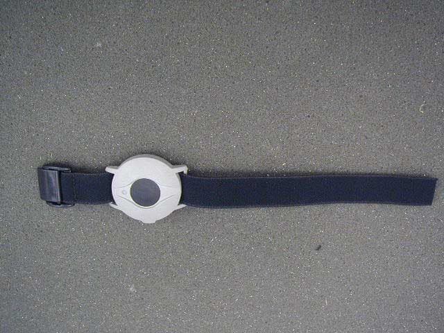
Click to zoom
Application Details
- Equipment Class
- DSC - Part 15 Security/Remote Control Transmitter
- Date of Grant
- Jul 31, 2002
- Application Purpose
- Original Equipment
- Date of Application
- Jul 31, 2002
- Equipment Note
- Emergency Alert Device
- Frequency Range
- 433.50000000 - 434.50000000
- Company
- Fidelity TeleAlarm LLC
- Country
- United States
Documents & Files
Document Text
Text extracted from the exhibit documents filed with the FCC. Open a document above to read the original.
Users Manual
TeleAlarm NurseCall2 INSTALLATION AND PROGRAMMING MANUAL FOR USE WITH MODEL NCM2 _______________________________________________________ Fidelity TeleAlarm, LLC 2501 Kutztown Road Reading, PA 19605-2961 Phone: (610) 929-4200 Fax: (610) 929-6861 E-mail: [email protected] http://www.fidelitytelealarm.com Document NC2-01.1 ©Copyright 2001 by Fidelity TeleAlarm, LLC PLEASE READ THE ENTIRE INSTALLATION AND PROGRAMMING MANUAL PRIOR TO START OF INSTALLATION AND USE. TABLE OF CONTENTS 2 SYSTEM OVERVIEW System Overview....................................................................................................................................3 Fidelity TeleAlarm® NurseCall 2 : Advanced Wireless Nurse Calling System ......................4 Operating Devices: Parts Diagram and Labels................................................................................6 UL 1069 Compliance.............................................................................................................................7 INITIAL SETUP How to Connect Optional Components to the RS232 Port...........................................................8 How to Install Backup Battery and Connect to Power Supply ......................................................9 Table and Wall Installation of Main and Local Receiver ..............................................................10 HOW TO PROGRAM THE NurseCall 2 Default Parameters..............................................................................................................................11 Select Language and Transmitter ID Code ....................................................................................11 How to Program the Locate 1 Option .......................................................................................12 How to Access the Programming Mode .........................................................................................13 Programming « Date and Time » .......................................................................................................14 Programming « Transmitter ID Number» ...........................................................................................15 Programming « RS232-Connection »...............................................................................................18 Programming « Local Receipt» (Reset) ............................................................................................20 Programming « Remote Receipt» (Reset)........................................................................................21 Programming « Language » ...............................................................................................................22 Programming « Relay as Closing or Switching Contact » .............................................................22 Nps Programming Software ...............................................................................................................23 How to Erase All Parameters ..............................................................................................................23 HOW TO USE THE NurseCall 2 Alarm and Event Buffers......................................................................................................................25 Display Indications...............................................................................................................................26 How to Reset Alarms/Messages ........................................................................................................27 Signaling of Alarms...............................................................................................................................28 Locate 1 Resident Locator System .................................................................................................29 Testing the Backup Battery ................................................................................................................30 How to Change Transmitter Batteries...............................................................................................30 HOW TO INSTALL OPTIONAL COMPONENTS RS232 Interface....................................................................................................................................34 • How to Install a Serial Printer......................................................................................................34 • How to Install the Multitone Paging System RPR 670 Series.................................................34 • Dispatcher ....................................................................................................................................36 Connecting Local Receivers through the RS485 Interface.........................................................36 • How to Connect Local Receivers ............................................................................................37 • How to Connect a Printer Interface ........................................................................................40 How to Install the IS75 Locate Beacon ............................................................................................41 How to Install the Wireless Door Contact RAC ...............................................................................43 Jumper Definitions of the Wireless Contact RAC ...........................................................................44 GENERAL INFORMATION Cleaning and Storage ...................................................................................................................... 45 Safety Instructions ................................................................................................................................46 FCC Requirements........................................................................................................................... ...47 Warranty ......................................…
Text truncated - open the document above for the full version.
External Photos
____ - Document Number: 160827 X MIYS37 Photo Section World Compliance Center MIYS37 Front of unit ____ - Document Number: 160827 X MIYS37 Photo Section World Compliance Center MIYS37 rear of unit ____ - Document Number: 160827 X MIYS37 Photo Section World Compliance Center MIYS37 rear -label area
ID Label/Location Info
____ - Document Number: 160827 X S37 Photo Section World Compliance Center MIYS37 Label ____ - Document Number: 160827 X S37 Photo Section World Compliance Center MIYS37 Label ____ - Document Number: 160827 X S37 Photo Section World Compliance Center MIYS37 Label
Internal Photos
____ - Document Number: 160827 X MIYS37 Photo Section World Compliance Center MIYS37 Rear of PCB ____ - Document Number: 160827 X MIYS37 Photo Section World Compliance Center MIYS37 front of PCB ____ - Document Number: 160827 X MIYS37 Photo Section World Compliance Center MIYS37 front of PCB ____ - Document Number: 160827 X MIYS37 Photo Section World Compliance Center MIYS37 rear of unit- battery contacts
Test Report
LAIRD TECHNOLOGIES – WORLD COMPLIANCE CENTER FCC PART 15 CERTIFICATION Document No.RevisionIssue Date Manufacturer: Fidelity TeleAlarm, LLC 160827 XREV A29 July 2002 EUT: S37 Wrist Pendant Purchase Order No.Page FCC ID: MIYS37 01-2881 of 21 EMC TEST REPORT Manufacturer: Fidelity TeleAlarm, LLC Equipment Under Test:S37 Wrist Pendant Test Report No.:160827 X Purchase Order No.:01-288 DOCUMENT HISTORY RevisionIssue Date Affected Page(s)Description of Modifications Revised By Approved By 029 July 2002Initial release REV A29 July 20028Section 7.2 Operating mode REV A29 July 200210Section 8.4 Duty Cycle Correction Factors REV A29 July 200217Correction Factors FILE: \\IS_SERVER\EMCSHARE\WORKING\FIDELITY\160827\FCC S37 TEST REPORT.DOC, NB#: 165 LAIRD TECHNOLOGIES – WORLD COMPLIANCE CENTER FCC PART 15 CERTIFICATION Document No.RevisionIssue Date Manufacturer: Fidelity TeleAlarm, LLC 160827 XREV A29 July 2002 EUT: S37 Wrist Pendant Purchase Order No.Page FCC ID: MIYS37 01-2883 of 21 TABLE OF CONTENTS (This document contains a total of 21 pages.) 1INTRODUCTION ............................................................................................................................................................4 1.1D ESCRIPTION O F W ORLD C OMPLIANCE C ENTER ............................................................................................................4 1.2S UMMARY OF W ORK D ONE ............................................................................................................................................4 1.2.1Summary of EMC Emission Tests .......................................................................................................................4 1.2.2Summary Conclusion / Declaration......................................................................................................................4 2CLIENT INFORMATION ..............................................................................................................................................4 3EQUIPMENT UNDER TEST (EUT) .............................................................................................................................5 3.1I DENTIFICATION OF EUT ................................................................................................................................................5 3.2D ESCRIPTION OF S YSTEM ...............................................................................................................................................5 3.3T ABLE : C OMPONENTS OF THE EUT ...............................................................................................................................5 3.4T ABLE : C ABLING OF THE EUT.......................................................................................................................................5 3.5A CCESSORY /P ERIPHERAL E QUIPMENT ............................................................................................................................5 3.6M ODIFICATIONS I NCORPORATED IN THE EUT.................................................................................................................5 3.7C ONFIGURATION OF T ESTED S YSTEM .............................................................................................................................6 4PRODUCT LABELING ..................................................................................................................................................7 4.1L OCATION OF L ABEL ON EUT ........................................................................................................................................7 5TEST SPECIFICATION, METHODS & PROCEDURES ..........................................................................................7 5.1I NTENTIONAL R ADIATORS ..............................................................................................................................................7 6DEVIATIONS, EXCLUSIONS FROM THE TEST SPECIFICATION .....................................................................8 6.1D EVIATIONS ...................................................................................................................................................................8 6.2E XCLUSIONS ...................................................................................................................................................................8 7OPERATION OF EUT DURING TESTING.................................................................................................................8 7.1O PERATIONAL E NVIRONMENT ........................................................................................................................................8 7.2O PERATING M ODE ( S ) .....................................................................................................................................................8 7.3R ELATED S UBMITTAL G RANTS .......................................................................................................................................8 8DETAILED TEST RESULTS .........................................................................................................................................9 8.1A NTENNA R EQUIREMENTS ..............................................................................................................................................9 8.2R ADIATED E MISSIONS .....................................................................................................................................................9 8.2.1FCC Part 15 Radiated Emissions Test Results.....................................................................................................9 8.3O CCUPIED B ANDWIDTH ................................................................................................................................................10 8.3.1FCC Part 15, Paragraph 15.231 (C) ........…
Text truncated - open the document above for the full version.
Test Setup Photos
____ - Document Number: 160827 X S37 Photo Section World Compliance Center Class B radiated emissions at 3 meters Class B radiated emissions at 3 meters
Contact Information
Applicant
Marilou Nagy(Marketing Coordinator)
Test Firm
Laird TechnologiesBridget Keesser
Technical Specifications
| # | Rule Parts | Frequency Range | Power Output |
|---|---|---|---|
| 1 | 15.231 | 433.5 MHz - 434.5 MHz | - |
Other Applications from Fidelity TeleAlarm LLC
MIYN45
Mar 02, 1998Remote Alarm
Equipment Class
DXX - Part 15 Low Power Communication Device TransmitterMIYMOD-10
Feb 27, 1997RF Transmitter Module
Equipment Class
DSC - Part 15 Security/Remote Control TransmitterMIYMOD-9
Feb 27, 1997RF Transmitter Module
Equipment Class
DSC - Part 15 Security/Remote Control TransmitterMIYS-R9
Feb 27, 1997Alarm System Receiver
Equipment Class
CYY - Communications Receiver used w/Pt 15 TransmitterMIYS10
Feb 27, 1997Alarm System Receiver
Equipment Class
CYY - Communications Receiver used w/Pt 15 Transmitter