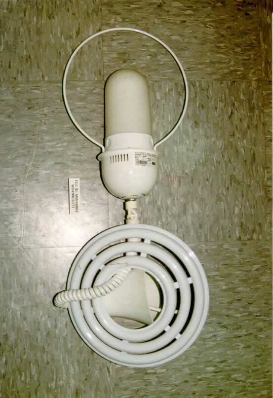
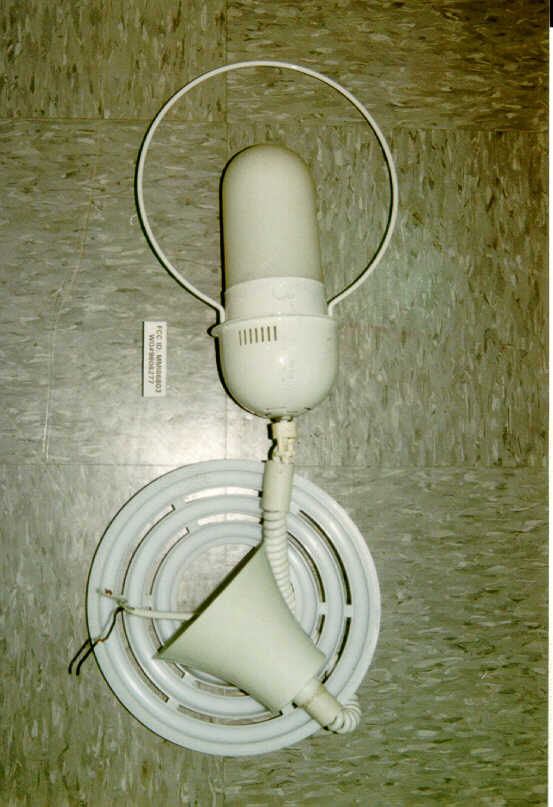
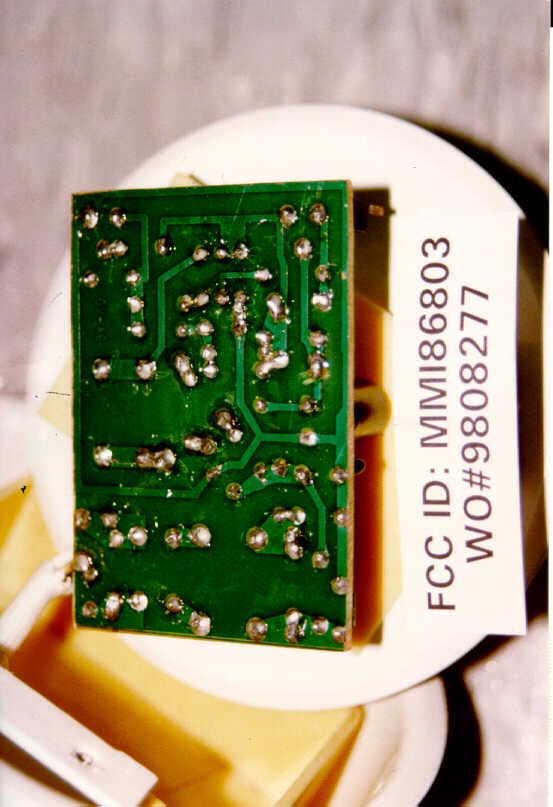
MMI86803Fluorescent Pendant Lamp
Jiadianbao Electrical Products (Shenzhen) Co., Ltd.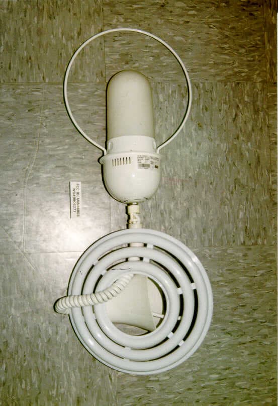
Click to zoom
Application Details
- Equipment Class
- 8CC - Part 18 Consumer Device
- Date of Grant
- Jan 24, 1999
- Application Purpose
- Original Equipment
- Date of Application
- Nov 26, 1998
- Equipment Note
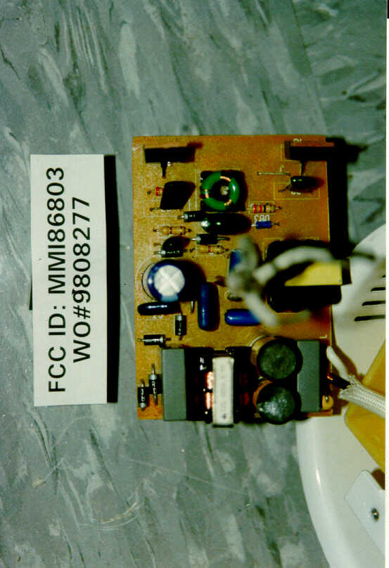
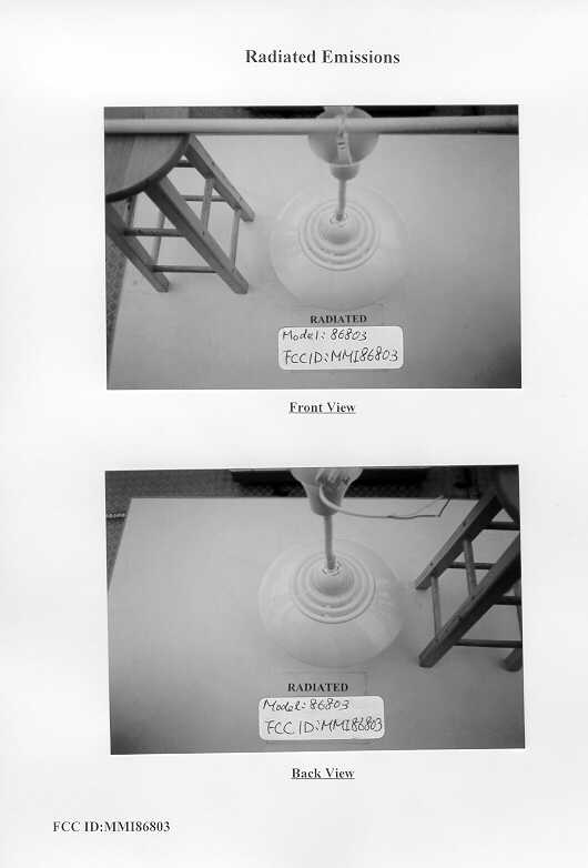
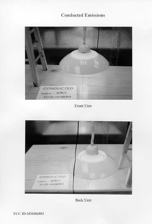
- Fluorescent Pendant Lamp
- Frequency Range
- 0.04700000 - 0.04700000
- Country
- China
Documents & Files
Document Text
Text extracted from the exhibit documents filed with the FCC. Open a document above to read the original.
Test Report
Model AP-1648 Spread Spectrum Data Transmitter and Model AP-1221 Interface Module Specifications Circuit Diagrams Technical Description Alignment Procedures 2 CONTENTS 1. Introduction 3 2. Specifications 3 3. Technical Description 3.1 General4 3.2 System Block Diagram4 3.3 Power Supply5 3.4 Microprocessor5 3.5 Frequency Synthesizer5 3.6 Modulator5 3.7 R.F. Amplifier and Harmonic Filter6 3.8 Emission Types6 3.9 Antenna6 4. AP-1221 Interface Module 6 5. Spread Spectrum Operation 5.1 Frequency Plan7 5.2 Per Hop Activities8 6. Alignment Procedure 9 7. FCC / ISC Identification Label and Placement 7.1 FCC and ISC Identification Label10 7.2 Serial Number Label10 7.3 Label Placement11 Schematic Diagrams / Component Layouts 1648 Transmitter Module Component Layout12 1221 Interface Module Component Layout13 DSCH-1648-01 Sheet 214 DSCH-1648-01 Sheet 315 DSCH-1221-0216 1. Introduction 3 The AP-1648 is a frequency hopped spread spectrum transmitter designed to be compatible with US (FCC Part 15.247) and Canadian (RSS-210) regulations for license free use in the 902-928 MHz band. The transmitter will typically be used for the remote control of industrial equipment such as cranes, concrete pumpers, loaders, etc. It will be used in conjunction with an existing OMNEX interface module that allows the connection of switches, potentiometers, joysticks etc. as required for a particular control application. The transmitter and interface module are housed in an ABS plastic enclosure with an internal antenna. Power is provided by a standard Makita power tool (Ni-Cad) battery pack. 2. Specifications Operating Frequency Range: 902-928 MHz Number of Radio Channels: 256 RF Output Power: 100 Milliwatts Frequency Stability: 2.5PPM from -30C to +70C. (Synthesized with TCXO reference osc.) Type of Emission: Frequency Hopped Spread Spectrum Power Supply: 9.6 volt power tool battery. (Makita) 4 3. Technical Description 3.1 General The AP-1648 is a frequency hopped spread spectrum transmitter designed to be compatible with U.S. (FCC Part 15.247) and Canadian (RSS-210) regulations for license free use in the 902-928 MHz band. The major elements include a frequency agile, narrow band transmitter and frequency hopping software for sequence generation and acquisition/tracking. The AP-1648 transmitter sends packets of telemetry and control data to compatible receivers (OMNEX REX-900). One data packet is sent on each frequency in the hop sequence. A data packet contains a transmit start flag, a transmit address, 11 bytes of user data and a CRC -16 error detection check sum. A data packet is formed (in a 68HC11E9 microprocessor), then digitally filtered (in a PIC processor), before FM modulation onto the transmit VCO. The transmitter generates a Reed-Solomon pseudo random frequency hop sequence of length 64 based on a pre- programmed seed. The full 902 to 928MHz band is utilized in equally spaced 30KHz channels. The hop dwell time is 20 milliseconds for a total sequence repetition time of 1.26 seconds. The transmitter system includes a AP-1648 RF transmitter module and a 1221 interface module enclosed in an ABS enclosure. The enclosure may contain control switches and/or potentiometers (dials or joysticks) as required for a particular application. The following diagram depicts the transmitter system in block diagram form. 3.2 System Block Diagram - FREQUENCY CONTROL - DATA ENCODING 1mW MODULATION J4 CONTROL SWITCHES AND/OR POTENTIOMETERS RF TRANSMITTER MODULE AP-1221 9.6V BATTERY INTERFACE HEADER J11 SYNTHESIZER LOCK DETECT SYNTHESIZER FREQUENCY CONTROL DIGITAL DATA RF P.A. HARMONIC FILTER MODULATION FILTER AP-1648 R32 902-928MHz L2-L4, C10-C13 100mW 902-928MHz MAIN MICROPROCESSOR (U7) INTERFACE HEADER J2 Secondary Microprocessor (U5) Op Amp (U5) INTERFACE MODULE Figure 1 Transmitter System Block Diagram FCC ID: IA9FH1648T 8.0 MHz X1 902-928MHz VCO (U4) SYNTHESIZER (U3) TCXO 12.8MHz (U12) FREQUENCY SYNTHESIS 5 3.3 Power Supply See schematic diagram DSCH-1648-01 sheets 2 & 3. The transmitter is powered by standard 9.6 volt power tool battery (Makita). Power enters at J1 on the 1221 interface module and is applied, through the header connector (J2), to the 1648 transmitter module. DC power is applied to switching regulator, U8 on the 1648 module, through Q3 and Q4. The 3.3VDC regulated output of the switching regulator supplies all circuits except the VCO. The VCO circuitry is supplied by a separate 3.3 volt linear regulator (U1). 3.4 Microprocessor See schematic diagram DSCH-1648-01 sheet 3. A Motorola 68HC11E9 microprocessor (U7) is employed to handle loading the synthesizer counter, packet formatting and interface functions. Crystal X1 provides an 8.00MHz clock while voltage comparator U11 holds the microprocessor in reset if the supply voltage is not within acceptable limits. A "lock" detect signal, supplied by the synthesizer, is also monitored by U7 which will shut down the transmitter in the event of a synthesizer malfunction. Connector J2 is used to attach an interface module which allows the microprocessor to be interfaced to external switches or potentiometers as required in the control of industrial machinery. All connector pins are bypassed with capacitors (C60-C83) to reduce noise, EMI etc. 3.5 VCO/Frequency Synthesizer See schematic diagram DSCH-1648-01 sheet 2. The frequency synthesizer is the heart of the transmitter hardware. The RF oscillator is provided by a Maxim 2620 VCO IC, (U4). The resonant tank circuit is comprised of L8, C27,C18 and Varactor diode D1. D1 provides the necessary frequency pulling capability. U4 contains separate output buffers for the RF and synthesizer drive. The frequency synthesizer is a Philips SA7025 (U3), which is programmed by the microprocessor with the frequency hopping sequence. The synthesizer loop filter consists of R23-R25 and C37-C39. A 12.8MHz TCXO (U12) provides a stable reference oscillator. 3.6 Modulator See schematic diagram DSCH-1648-01 sheet 2. The transmitter employs a…
Text truncated - open the document above for the full version.
Contact Information
Applicant
Mr. Y. G. Yang(Assistant Manager, Standard Dept)
Technical Contact
INTERTEK TESTING SERVICES HONG KONG LTD.C.K. LAM
[email protected](852)2746-8211
2/F., GARMENT CENTRE, · KOWLOON · Hong Kong
Non-Technical Contact
INTERTEK TESTING SERVICES HONG KONG LTD.C.K. LAM
[email protected](852)2746-8211
Test Firm
Intertek Testing Services Hong KongBilly Chow
Technical Specifications
| # | Rule Parts | Frequency Range | Power Output |
|---|---|---|---|
| 1 | 18 | 0.047 MHz - 0.047 MHz | - |
Other Applications from Jiadianbao Electrical Products (Shenzhen) Co., Ltd.
MMIG6158
Jun 19, 2005pencil sharpener lamp rated 35W
Equipment Class
8CC - Part 18 Consumer Device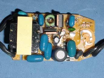
MMIG1065
Nov 19, 2003Portable Luminaire Rated 50W
Equipment Class
8CC - Part 18 Consumer Device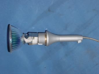
MMIG90035
Mar 24, 2003Track Lighting Rated 50W
Equipment Class
8CC - Part 18 Consumer Device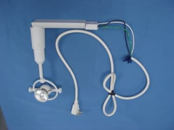
MMIG90022
Oct 13, 2002Tracking Lighting Rated 50W
Equipment Class
8CC - Part 18 Consumer Device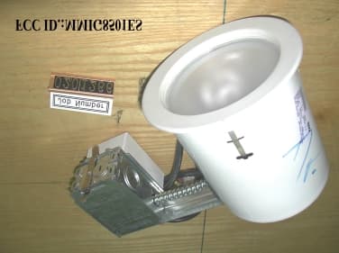
MMIG8501ES
May 19, 2002Fluorescent Recessed Lamp
Equipment Class
8CC - Part 18 Consumer Device