MP3-9001G-0411802.11g 54M Wireless LAN USB Adapter
Surecom Technology Corporation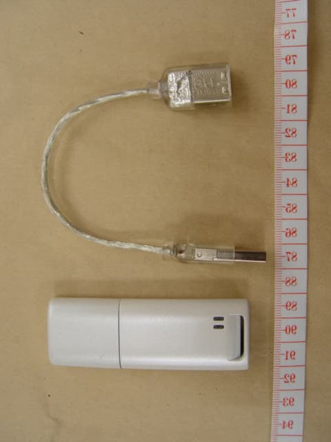
Click to zoom
Application Details
- Equipment Class
- DTS - Digital Transmission System
- Date of Grant
- Jan 26, 2005
- Application Purpose
- Original Equipment
- Date of Application
- Jan 26, 2005
- Equipment Note
- 802.11g 54M Wireless LAN USB Adapter
- Frequency Range
- 2412.00000000 - 2472.00000000
- Country
- Taiwan
Documents & Files
Document Text
Text extracted from the exhibit documents filed with the FCC. Open a document above to read the original.
Users Manual
EP-9001-g 54M WLAN USB Adapter User Manual 2 4819428GZ000 1.Introduction--------------------------------------------------------------------------------------------------------3 1.1Feature-------------------------------------------------------------------------------------------------------------3 1.2Specification------------------------------------------------------------------------------------------------------4 1.3Package Contents---------------------------------------------------------------------------------------------- 4 1.4Systems Requirements----------------------------------------------------------------------------------------5 2.Hardware Installation------------------------------------------------------------------------------------------5 2.1Connecting the WLAN USB Adapter-----------------------------------------------------------------------5 2.2 Removing the WLAN USB Adapter------------------------------------------------------------------------6 3.Software Installation-------------------------------------------------------------------------------------------7 3.1Installing WLAN USB Adapter Utility and Driver--------------------------------------------------------7 3.2Uninstalling the Driver and Utility---------------------------------------------------------------------------11 4.Configuration Utility--------------------------------------------------------------------------------------------14 4.1Using the configuration utility---------------------------------------------------------------------------------14 4.1.1Profile---------------------------------------------------------------------------------------------------------15 4.1.1.1 System Configuration Edit profile Network Type--------------------------------------------15 4.1.1.2 Edit Profile---------------------------------------------------------------------------------------------17 4.1.1.3 Authentication and Security-----------------------------------------------------------------------19 4.1.2 Link Status---------------------------------------------------------------------------------------------------20 4.1.3 Site Survey---------------------------------------------------------------------------------------------------21 4.1.4 Statistics----------------------------------------------------------------------------------------------------- 22 4.1.5 Advance----------------------------------------------------------------------------------------------------- 23 4.1.6 About--------------------------------------------------------------------------------------------------------- 24 5.Glossary------------------------------------------------------------------------------------------------------------ 25 3 1 Introduction The 802.11g WLAN USB Adapter provides greater performance than ever before. Incorporated with latest IEEE 802.11g technology, the WLAN USB Adapter is not only compliant with other 802.11g products but allows you to connect with other 802.11b devices. With WPA (Wi-Fi Protected Access) and 64/128-bit WEP encryption, the WLAN USB Adapter ensure the security of your network communication. All you need is laptop computer with one USB1.1/ USB 2.0 interface and Windows 98SE/2000/ME/XP operating system; the Plug-and-Play feature will enable you to complete the set up process within minutes. This WLAN USB Adapter has been designed for both home and business users, enables you to communicate seamlessly with other wireless networking products wherever you are. 1.1 Features 1.IEEE 802.11b-DSSS (BPSK,QPSK,CCK) 2.IEEE 802.11g-OFDM(64-QAM,16-QAM,QPSK,BPSK) 3.54Mbps high Data Rate 4.Support USB 1.1/USB 2.0 interface. 5.Auto Rate fallback for optimizing communication possibility in worse channel conditions and over larger distances. 6.64/128bit WEP data encryption security 7.Compliant with Windows 98SE/2000/ME/XP 8.Power save in infrastructure mode. 9.Build-in PCB patch antenna. 10.Plug-and-Play and easy to setup. 11.Easy-to-Use Graphical Configuration utility saves detailed connectivity profiles for frequently accessed networks. 4 1.2 Specification Model:802.11g WLAN USB Adapter Radio:Complies with IEEE 802.11b/g Frequency Band:2.412-2.462GHz(U.S.) 2.412-2.484GHz(Japan)2.412-2.472GHz(ETSI) Modulation TYPE :BPSK,QPSK,CCK,16-QAM,64-QAM Operating Channels:11 channels (US)13 channels (ETSI)14 channels (Japan) Data Rate:1 / 2 / 5.5 / 6/9/11/12/24/36/48/54Mbps Output Power: 18dBm@11Mbps;15dBm@54Mbps Receive sensitivity: Min.-80dBm for 11Mbps (@BER 8%) Min. -70dBm for 54 Mbps(@FER 10%) Antenna Type: Build-in PCB patch antenna Current Consumption: 3.3V, Tx mode 400 mA (Max.) Rx mode 250 mA (Max.) Certification:Radio: EU: ETS 300 328; USA: FCC Part 15C EMC: EU ETS 300 826; USA: FCC Part 15B Safety: EN60950 Driver:Windows 98SE/2000/ME/XP 1.3 Package Contents 1.One 802.11g WLAN USB Adapter. 2.One setup Utility CD-ROM (User’s Guide on CD). 3.Quick Installation Guide. 4.1m USB cable 5 1.4 Systems Requirements 1.One USB 1.1/ USB 2.0 slot. 2.A laptop computer with an available USB1.1 / USB 2.0 slot. 3.Operating System: Windows 98SE/2000/ME/XP 4.60M bytes free disk space for utility and driver installation. Note : If you insert the 802.11g WLAN USB Adapter before installing the driver and utility, the operating system will detect a new device and start to configure the new device. Click Cancel to finish the wizard. Follow the instruction step by step to install the WLAN USB Adapter. 2.Hardware Installation 2.1Connecting the WLAN USB Adapter Insert the WLAN USB Adapter into the USB slot on your notebook. 6 2.2 Removing the WLAN USB Adapter If you want to remove the WLAN USB Adapter, you can direct remove the WLAN USB Adapter out of the slot. 7 3.Software Installation 3.1Installing WLAN USB Adapter Utility and Driver Insert the setup CD into your CD-ROM Device. Then, the Install ShieldWizard should launch automatically, if it does not launch automatically, Double-click setup.exe in your CD-ROM Drive. 8 Click Next button in the following win…
Text truncated - open the document above for the full version.
Cover Letter(s)
SURECOM TECHNOLOGY CORPORATION 6F, No. 125, Sec 2, Datung Rd., Shijr City, Taipei 221, Taiwan, R.O.C. Federal Communications Commission FCC ID : MP3-9001G-0411 Dear Sir: This is to request confidentiality on information submitted for above application. We would like to request confidentiality on some exhibits we submitted for above original application for the reason of trade secret. If those exhibits are available for public inspection, any person who once gets the information contained in those exhibits will be able to design and to make the same products very easily. This is a very serious problem and huge loss for us, because we did invest so much on it. Please be not made the Exhibit Types listed below routinely available for public inspection: Part lists, block diagram, and schematics By: By: Ken Wang ( Signature ) ( Printed ) Title: Applicant: Surecom Technology Corporation . Address: 6F, No. 125, Sec.2, Datung Rd., Shijr City,Taipei 221, Taiwan R.O.C. Tel: +886-2-8692-6200 Fax: +886-2-8692-6203 Date: Jan. 04. 2005
Cover Letter(s)
SURECOM TECHNOLOGY CORPORATION 6F, No. 125, Sec 2, Datung Rd., Shijr City, Taipei 221, Taiwan, R.O.C. Federal Communications Commission Dear Sir, We, the undersigned, hereby authorize ETS Dr.Genz Taiwan PS Co.,Ltd. to act on our behalf in all matters relating to application for Product Name : ” 802.11g 54M Wireless LAN USB Adapter, Mode l Number : EP/NE-9001-g, FCC ID : MP3 -9001G-0411 ” authorization, including the signing of all documents relating to these matters. Any and all acts carried out by ETS Dr.Genz Taiwan PS Co.,Ltd. on our behalf shall have the same effect as acts of our own. The applicant certifies that in the case of an individual applicant ( e.g., corporation ), no party to the applicant is subject to a denial of federal benefits, that includes FCC benefits, pursuant to section 5301 of the Anti-drug abuse act of 1988.21 U.S.C.862. For a definition of a “ party ” for these purposes see 47 C.F.R.1.200(b). By: By: Ken Wang ( Signature ) ( Printed ) Title: Applicant: Surecom Technology Corporation . Address: 6F, No. 125, Sec.2, Datung Rd., Shijr City,Taipei 221, Taiwan R.O.C. Tel: +886-2-8692-6200 Fax: +886-2-8692-6203 Date: Jan. 04. 2005
External Photos
Registration number: W6M20412-5549-C-1 FCC ID: MP3-9001G-0411 ________________________________________________________________________________ ETS Dr. Genz GmbH, Germany ELECTRONIC TECHNOLOGY SYSTEMS DR.GENZ GMBH External Photo ELECTRONIC TECHNOLOGY SYSTEMS DR.GENZ GMBH Registration number: W6M20412-5549-C-1 FCC ID: MP3-9001G-0411 ETS Dr. Genz GmbH, Germany ELECTRONIC TECHNOLOGY SYSTEMS DR.GENZ GMBH Registration number: W6M20412-5549-C-1 FCC ID: MP3-9001G-0411 ETS Dr. Genz GmbH, Germany ELECTRONIC TECHNOLOGY SYSTEMS DR.GENZ GMBH Registration number: W6M20412-5549-C-1 FCC ID: MP3-9001G-0411 ETS Dr. Genz GmbH, Germany
ID Label/Location Info
32 mm 10 mm
RF Exposure Info
MPE Prediction FCC Rule: 15.247(b)(5) Systems operating under the provisions of this section shall be operated in a manner that ensures that the public is not exposed to radio frequency energy levels in excess of the Commission’s guidelines. See §1.1307(b)(1) of this Chapter. LIMITS FOR MAXIMUM PERMISSIBLE EXPOSURE (MPE) Frequency Range (MHz) Electric Field Strength (V/m) Magnetic Field Strength (A/m) Power Density (mW/cm2) Average time (minutes) (A)Limits For Occupational / Control Exposures 30-300 61.4 0.613 1.0 6 300-1500 ... ... F/300 6 1500-100,000 ... ... 5 6 (B)Limits For General Population / Uncontrolled Exposure 30-300 27.5 0.073 0.2 30 300-1500 ... ... F/1500 30 1500-100,000 ... ... 1.0 30 F = Frequency in MHz Prediction of MPE limit at a given distance Equation from page 18 of OET Bulletin 65, Edition 97-01 PG S = -------------- 4 R² where: S = power density P = power input to the antenna G = power gain of the antenna in the direction of interest relative to an isotropic radiator R = distance to the center of radiation of the antenna Maximum peak output power at antenna input terminal: 23.85 (dBm) Maximum peak output power at antenna input terminal: 242.66 (mW) Antenna gain(maximal): 1.6 (dBi) Prediction distance: 20 (cm) Prediction frequency: 2412 (MHz) MPE limit for uncontrolled exposure at prediction frequency: 1.0 (mW/cm²) Power density at prediction frequency: 0.07724 (mW/cm²) The manual instruct the user to install and operate the device in a minimum distance of 20 cm between antenna and the users body.
RF Exposure Info
MPE Prediction FCC Rule: 15.247(b)(5) Systems operating under the provisions of this section shall be operated in a manner that ensures that the public is not exposed to radio frequency energy levels in excess of the Commission’s guidelines. See §1.1307(b)(1) of this Chapter. LIMITS FOR MAXIMUM PERMISSIBLE EXPOSURE (MPE) Frequency Range (MHz) Electric Field Strength (V/m) Magnetic Field Strength (A/m) Power Density (mW/cm2) Average time (minutes) (A)Limits For Occupational / Control Exposures 30-300 61.4 0.613 1.0 6 300-1500 ... ... F/300 6 1500-100,000 ... ... 5 6 (B)Limits For General Population / Uncontrolled Exposure 30-300 27.5 0.073 0.2 30 300-1500 ... ... F/1500 30 1500-100,000 ... ... 1.0 30 F = Frequency in MHz Prediction of MPE limit at a given distance Equation from page 18 of OET Bulletin 65, Edition 97-01 PG S = -------------- 4 R² where: S = power density P = power input to the antenna G = power gain of the antenna in the direction of interest relative to an isotropic radiator R = distance to the center of radiation of the antenna Maximum peak output power at antenna input terminal: 24.56 (dBm) Maximum peak output power at antenna input terminal: 285.759 (mW) Antenna gain(maximal): 1.6 (dBi) Prediction distance: 20 (cm) Prediction frequency: 2412 (MHz) MPE limit for uncontrolled exposure at prediction frequency: 1.0 (mW/cm²) Power density at prediction frequency: 0.09096 (mW/cm²) The manual instruct the user to install and operate the device in a minimum distance of 20 cm between antenna and the users body.
Test Report
ELECTRONIC TECHNOLOGY SYSTEMS DR. GENZ GMBH FCC TEST - REPORT FCC Part 15 C for IEEE 802.11b device FCC ID: MP3-9001G-0411 Test report no.: W6M20412-5549-C-1 ELECTRONIC TECHNOLOGY SYSTEMS STORKOWER STRASSE 38C, D-15526 REICHENWALDE B. BERLIN DR. GENZ GMBH PHONE +49-33631-888 00 FAX +49-33631-888 66 ELECTRONIC TECHNOLOGY SYSTEMS DR.GENZ GMBH Registration number: W6M20412-5549-C-1 FCC ID: MP3-9001G-0411 ETS Dr. Genz GmbH, Germany 2 of 35 TABLE OF CONTENTS 1 GENERAL INFORMATION...................................................................................................3 1.1 NOTES...................................................................................................................................3 1.2 TESTING LABORATORY.........................................................................................................4 1.2.1 Location.......................................................................................................................4 1.2.2 Details of accreditation status.....................................................................................4 1.3 DETAILS OF APPROVAL HOLDER............................................................................................4 1.4 APPLICATION DETAILS..........................................................................................................5 1.5 GENERAL INFORMATION OF TEST ITEM.................................................................................5 1.6 TEST STANDARDS..................................................................................................................7 2 TECHNICAL TEST..................................................................................................................8 2.1 SUMMARY OF TEST RESULTS.................................................................................................8 2.2 TEST ENVIRONMENT..............................................................................................................8 2.3 TEST EQUIPMENT LIST..........................................................................................................9 2.4 GENERAL TEST PROCEDURE...............................................................................................16 3 TEST RESULTS (ENCLOSURE)..........................................................................................18 3.1 PEAK OUTPUT POWER (TRANSMITTER)...............................................................................19 3.2 EQUIVALENT ISOTROPIC RADIATED POWER.........................................................................20 3.2.1 Transmitter.................................................................................................................20 3.3 RF EXPOSURE COMPLIANCE REQUIREMENTS.....................................................................20 3.4 TRANSMITTER RADIATED EMISSIONS IN RESTRICTED BANDS.............................................21 3.5 SPURIOUS EMISSIONS (TX)..................................................................................................22 3.6 MINIMUM 6 DB BANDWIDTH..............................................................................................25 3.7 PEAK POWER SPECTRAL DENSITY.......................................................................................26 3.8 POWER LINE CONDUCTED EMISSION..................................................................................27 APPENDIX.......................................................................................................................................28 APPENDIX A....................................................................................................................................29 APPENDIX B....................................................................................................................................30 APPENDIX C....................................................................................................................................31 APPENDIX D....................................................................................................................................32 APPENDIX E....................................................................................................................................33 APPENDIX F....................................................................................................................................34 APPENDIX G....................................................................................................................................35 ELECTRONIC TECHNOLOGY SYSTEMS DR.GENZ GMBH Registration number: W6M20412-5549-C-1 FCC ID: MP3-9001G-0411 ETS Dr. Genz GmbH, Germany 3 of 35 1 General Information 1.1 Notes The purpose of conformity testing is to increase the probability of adherence to the essential requirements or conformity specifications, as appropriate. The complexity of the technical specifications, however, means that full and thorough testing is impractical for both technical and economic reasons. Furthermore, there is no guarantee that a test sample which has Passed all the relevant tests conforms to a specification. Neither is there any guarantee that such a test sample will interwork with other genuinely open systems. The existence of the tests nevertheless provides the confidence that the test sample possesses the qualities as maintained and that is performance generally conforms to representative cases of communications equipment. The test results of this test report relate exclusively to the item tested as specified in 1.5. The test report may only be reproduced or published in full. Reproduction or publication of extracts from the report requires the prior written approval of the ELECTRONIC TECHNOLOGY SYSTEMS DR. GENZ GMBH. Specific Conditions: Usage of the hereunder tested device in combination with other integrated or external antennas requires at least additional output power measure…
Text truncated - open the document above for the full version.
Test Report
ELECTRONIC TECHNOLOGY SYSTEMS DR. GENZ GMBH FCC TEST - REPORT FCC Part 15 C for IEEE 802.11g device FCC ID: MP3-9001G-0411 Test report no.: W6M20412-5549-C-2 ELECTRONIC TECHNOLOGY SYSTEMS STORKOWER STRASSE 38C, D-15526 REICHENWALDE B. BERLIN DR. GENZ GMBH PHONE +49-33631-888 00 FAX +49-33631-888 66 ELECTRONIC TECHNOLOGY SYSTEMS DR.GENZ GMBH Registration number: W6M20412-5549-C-2 FCC ID: MP3-9001G-0411 ETS Dr. Genz GmbH, Germany 2 of 35 TABLE OF CONTENTS 1 GENERAL INFORMATION...................................................................................................3 1.1 NOTES...................................................................................................................................3 1.2 TESTING LABORATORY.........................................................................................................4 1.2.1 Location.......................................................................................................................4 1.2.2 Details of accreditation status.....................................................................................4 1.3 DETAILS OF APPROVAL HOLDER............................................................................................4 1.4 APPLICATION DETAILS..........................................................................................................5 1.5 GENERAL INFORMATION OF TEST ITEM.................................................................................5 1.6 TEST STANDARDS..................................................................................................................7 2 TECHNICAL TEST..................................................................................................................8 2.1 SUMMARY OF TEST RESULTS.................................................................................................8 2.2 TEST ENVIRONMENT..............................................................................................................8 2.3 TEST EQUIPMENT LIST..........................................................................................................9 2.4 GENERAL TEST PROCEDURE...............................................................................................16 3 TEST RESULTS (ENCLOSURE)..........................................................................................18 3.1 PEAK OUTPUT POWER (TRANSMITTER)...............................................................................19 3.2 EQUIVALENT ISOTROPIC RADIATED POWER.........................................................................20 3.2.1 Transmitter.................................................................................................................20 3.3 RF EXPOSURE COMPLIANCE REQUIREMENTS.....................................................................20 3.4 TRANSMITTER RADIATED EMISSIONS IN RESTRICTED BANDS.............................................21 3.5 SPURIOUS EMISSIONS (TX)..................................................................................................22 3.6 MINIMUM 6 DB BANDWIDTH..............................................................................................25 3.7 PEAK POWER SPECTRAL DENSITY.......................................................................................26 3.8 POWER LINE CONDUCTED EMISSION..................................................................................27 APPENDIX.......................................................................................................................................28 APPENDIX A....................................................................................................................................29 APPENDIX B....................................................................................................................................30 APPENDIX C....................................................................................................................................31 APPENDIX D....................................................................................................................................32 APPENDIX E....................................................................................................................................33 APPENDIX F....................................................................................................................................34 APPENDIX G....................................................................................................................................35 ELECTRONIC TECHNOLOGY SYSTEMS DR.GENZ GMBH Registration number: W6M20412-5549-C-2 FCC ID: MP3-9001G-0411 ETS Dr. Genz GmbH, Germany 3 of 35 1 General Information 1.1 Notes The purpose of conformity testing is to increase the probability of adherence to the essential requirements or conformity specifications, as appropriate. The complexity of the technical specifications, however, means that full and thorough testing is impractical for both technical and economic reasons. Furthermore, there is no guarantee that a test sample which has Passed all the relevant tests conforms to a specification. Neither is there any guarantee that such a test sample will interwork with other genuinely open systems. The existence of the tests nevertheless provides the confidence that the test sample possesses the qualities as maintained and that is performance generally conforms to representative cases of communications equipment. The test results of this test report relate exclusively to the item tested as specified in 1.5. The test report may only be reproduced or published in full. Reproduction or publication of extracts from the report requires the prior written approval of the ELECTRONIC TECHNOLOGY SYSTEMS DR. GENZ GMBH. Specific Conditions: Usage of the hereunder tested device in combination with other integrated or external antennas requires at least additional output power measure…
Text truncated - open the document above for the full version.
Test Setup Photos
ELECTRONIC TECHNOLOGY SYSTEMS DR.GENZ GMBH Registration number: W6M20412-5549-C-1 FCC ID: MP3-9001G-0411 ETS Dr. Genz GmbH, Germany Setup Photo ELECTRONIC TECHNOLOGY SYSTEMS DR.GENZ GMBH Registration number: W6M20412-5549-C-1 FCC ID: MP3-9001G-0411 ETS Dr. Genz GmbH, Germany ELECTRONIC TECHNOLOGY SYSTEMS DR.GENZ GMBH Registration number: W6M20412-5549-C-1 FCC ID: MP3-9001G-0411 ETS Dr. Genz GmbH, Germany ELECTRONIC TECHNOLOGY SYSTEMS DR.GENZ GMBH Registration number: W6M20412-5549-C-1 FCC ID: MP3-9001G-0411 ETS Dr. Genz GmbH, Germany ELECTRONIC TECHNOLOGY SYSTEMS DR.GENZ GMBH Registration number: W6M20412-5549-C-1 FCC ID: MP3-9001G-0411 ETS Dr. Genz GmbH, Germany ELECTRONIC TECHNOLOGY SYSTEMS DR.GENZ GMBH Registration number: W6M20412-5549-C-1 FCC ID: MP3-9001G-0411 ETS Dr. Genz GmbH, Germany ELECTRONIC TECHNOLOGY SYSTEMS DR.GENZ GMBH Registration number: W6M20412-5549-C-1 FCC ID: MP3-9001G-0411 ETS Dr. Genz GmbH, Germany ELECTRONIC TECHNOLOGY SYSTEMS DR.GENZ GMBH Registration number: W6M20412-5549-C-1 FCC ID: MP3-9001G-0411 ETS Dr. Genz GmbH, Germany
Contact Information
Applicant
Ken Wang(Engineer)
Technical Contact
ETS Dr. Genz TAIWAN PS CO., LTD.Steven Chuang
[email protected]+886-2-6606-8877
6F., No. 58, Lane 188, Ruey Kuang Road, Neihu · Taipei · Taiwan
Non-Technical Contact
ETS Dr. Genz TAIWAN PS CO., LTD.Lulu Lin
[email protected]+886-2-6606-8877
Test Firm
Eurofins Product Service GmbHRobert Kschiwan-Kaspar
Technical Specifications
| # | Rule Parts | Frequency Range | Power Output |
|---|---|---|---|
| 1 | 15C | 2.41 GHz - 2.47 GHz | 285.76 mW |
Other Applications from Surecom Technology Corporation
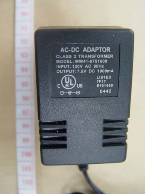
MP3-9610G-0503
Jul 02, 2005802.11g Wireless LAN Broad Router
Equipment Class
DTS - Digital Transmission System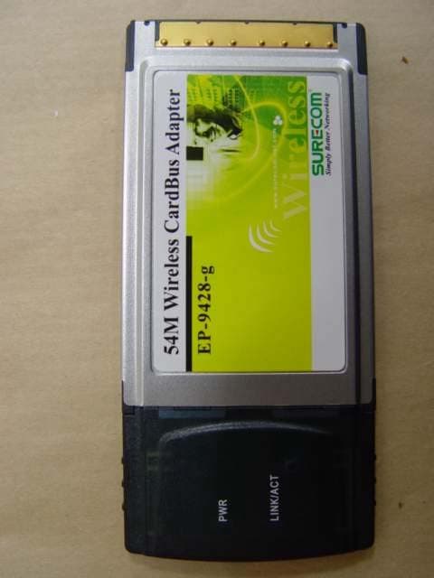
MP3-9428G-0404
Jun 07, 2004802.11g 54M WLAN CardBus Adapter
Equipment Class
DTS - Digital Transmission SystemMP3XZ841222
Oct 21, 1996JBP - Part 15 Class B Computing Device Peripheral
Equipment Class
JBP - Part 15 Class B Computing Device Peripheral