MQEE51-0386-40Super MOLE� Gold 2
Electronic Controls Design Inc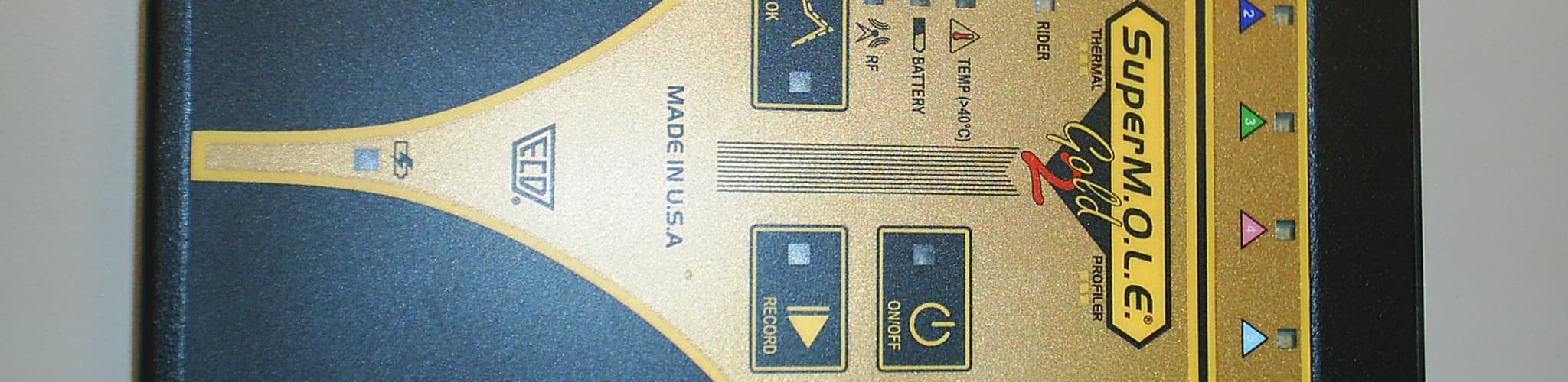
Click to zoom
Application Details
- Equipment Class
- DTS - Digital Transmission System
- Date of Grant
- Jun 12, 2011
- Application Purpose
- Original Equipment
- Date of Application
- Jun 12, 2011
- Equipment Note
- Super MOLE� Gold 2
- Frequency Range
- 2405.00000000 - 2480.12500000
- Country
- United States
Documents & Files
Document Text
Text extracted from the exhibit documents filed with the FCC. Open a document above to read the original.
Users Manual
Contents 1. Introduction .............................................................................................................................................. 4 1.1. Copyright ............................................................................................................................................ 4 1.2. Declaration of Conformity ................................................................................................................. 6 1.3. How to use this Users Help Guide ...................................................................................................... 8 1.4. Terms Used ........................................................................................................................................ 9 1.5. Fonts Used ....................................................................................................................................... 10 2. Safety ...................................................................................................................................................... 11 2.1. Operators Safety Information .......................................................................................................... 11 2.2. Battery Warnings ............................................................................................................................. 13 2.3. Equipment Maintenance ................................................................................................................. 14 2.4. Product Symbols .............................................................................................................................. 15 3. Equipment ............................................................................................................................................... 17 3.1. SuperM.O.L.E.® Gold ........................................................................................................................ 17 3.1.1. Power Pack ................................................................................................................................ 18 3.1.2. Calendar/Clock Battery ............................................................................................................. 19 3.1.3. Sensors ...................................................................................................................................... 20 3.1.4. Computer Interface Cable ......................................................................................................... 21 3.1.5. Uni-Barrier & Yellow Jacket ...................................................................................................... 22 3.2. SuperM.O.L.E.® Gold 2 ..................................................................................................................... 23 3.2.1. Sensors ...................................................................................................................................... 25 3.2.2. USB Computer Interface Cable ................................................................................................. 26 3.2.3. Barrier & Yellow Jacket ............................................................................................................. 27 3.2.4. Wireless RF Option .................................................................................................................... 28 4. Basics ....................................................................................................................................................... 29 4.1. Setup ................................................................................................................................................ 29 4.1.1. Charging the Power Pack .......................................................................................................... 29 4.1.2. Communications Setup ............................................................................................................. 32 4.2. Operation - Fresh Start .................................................................................................................... 43 4.3. Operation - Verify ............................................................................................................................ 61 5. Software .................................................................................................................................................. 80 5.1. Computer Hardware Requirements ................................................................................................. 80 5.2. Installation & Authorization ............................................................................................................. 81 5.2.1. Windows XP .............................................................................................................................. 83 5.2.2. Windows Vista .......................................................................................................................... 92 5.2.3. Windows 7 .............................................................................................................................. 102 5.3. Features ......................................................................................................................................... 111 5.3.1. AutoPlay .................................................................................................................................. 112 5.3.2. Page Tabs ................................................................................................................................ 112 5.3.3. Split Bar ................................................................................................................................... 113 5.3.4. Status Bar ................................................................................................................................ …
Text truncated - open the document above for the full version.
Users Manual
12) Select the Finish command button to complete the wizard and display the new calculation data in the selected template cell. 5.4.3.2.1.6. Integral (Y*time) To add or edit Speed (distance/time) content: 1) Right-click a template cell and a shortcut menu appears. 2) Select Add Content or Edit Content from the shortcut menu and the Add or Change a Calculation wizard appears. When navigating through the wizard, the step list on the left uses a color key to inform the user of the current step, steps that have been completed and remaining steps. Current Completed Remaining 3) Click Intergral (Y*time) and which channel to derive the data from 4) Select the Next command button. 5) Enter the Lower value to define the base of the integral calculation and an Upper value to define maximum value to include in the integral. To not restrict the maximum value of the integral, a very large value can be set for the Upper value. 6) Select the Next command button. 7) Select desired text formatting options. 8) Select the Next command button. 9) Select Specification Limits and Units. If these values are violated colored bars will appear in the formatted template cell. Refer to topic Software>Page Tabs>Spreadsheet>Template>Specification Limit Indicators for more information. 10) Select the Finish command button to complete the wizard and display the new calculation data in the selected template cell. 5.4.3.2.1.7. Special Value To add or edit Special Value content: 1) Right-click a template cell and a shortcut menu appears. 2) Select Add Content or Edit Content from the shortcut menu and the Add or Change a Calculation wizard appears. When navigating through the wizard, the step list on the left uses a color key to inform the user of the current step, steps that have been completed and remaining steps. Current Completed Remaining 3) Click Special Value. 4) Select the Next command button. 5) Select a Special Value type. 6) Select the Next command button. 7) Select desired text formatting options. 8) Select the Finish command button to complete the wizard and display the new calculation data in the selected template parameter column. 5.4.3.2.2. Specification Limit Indicators Each Parameter displayed on the Spreadsheet Page Tab can have both Lower and Upper specifications applied. If a specification limit is violated, the software displays a red or blue indicator on the left edge of the Data Table cell. If a USL has been exceeded, that parameter indicator will appear in red (indicating it is above the specification limit). If a parameter is less than the user specified LSL, that parameter indicator will be appear in blue (indicating below the specification limit). Refer to topic Software>Page Tabs>Spreadsheet>Template>Add & Edit Content for information on how to apply LSL and USL values. 5.4.3.3. Parameters When parameters are displayed on the Spreadsheet template, they include header, labels and unit cells. These parameters can be color coded with the associated Parameter Labels so they can be easily identified together. The width of each column can be adjusted to be larger or smaller by placing the mouse pointer over a split line dividing the columns and sliding it to the desired width. Parameter Headers The software includes two default parameter headers that display data run and user defined information. All headers displayed to the right of those display the description of the parameter. When editing or adding parameters, the software does not allow the default parameter description to be modified. Data Run Parameter Group: This group contains file information associated with the run such as; date and time, (of profile) and the data file tag. User Defined Parameter Group: These parameter columns can be used to enter text to help identify the row with unique information about that run (i.e. shift, operator, line number, part number). This information will also appear in the Tool Status box on the Profile worksheet. Parameter Labels The Parameter Labels display details associated with the displayed parameters. For example, in the Maximum Y Value parameter, the label is Channel 1. Parameter Units The Parameter Units are the units of measurement for the displayed parameter. For example, in the Maximum Positive Slope parameter, the parameter unit is °C/sec. 5.4.3.4. SPC Flags SPC Flags allow the user to flag parameters so they are displayed on the SPC Page Tab. For each Parameter listed after the User defined Parameters, there is an SPC Flag. To display the parameter data in an X-Bar and R-Chart format, select the desired SPC Flag. Refer to topic Software>Page Tabs>SPC Page Tab for more information. This is available when in Engineer Mode. 5.4.3.5. Data Run Rows All of the data runs in the open working directory are listed on the Spreadsheet Page Tab as individual rows. The first data run uploaded or imported into the directory is on the bottom and the most recent data run is on the top. When any data run row is selected, all of the cells in the entire row are highlighted in purple and blue. The purple cells indicate that the cells can be modified and the blue cells indicate the data cannot be modified. When any individual data cell in a data run row is selected, all of the cells in the entire row are highlighted in green and yellow. The green cells indicate that the cells can be modified and the yellow cells indicate the data cannot be modified. When a data run row is selected, the data for that row will also be displayed in the Sel= row located at the bottom of the data run rows. This row allows the user to easily compare the selected data row to the statistics calculations located below the selected run row. Selected rows and columns can be “copied” by pressing keys [CTRL + C] and then “pasted” [Ctrl + V] into other applications. The data run rows can also be moved into any order desired. This is useful when the user wants to place similar data runs together. To change the order of the data run: 1) Select th…
Text truncated - open the document above for the full version.
Users Manual
• Internal Temp: Indicates the current internal temperature of the M.O.L.E. Profiler. • RF Status: Signal strength indicator with 5 bars indicating relative strength of the RF signal. Save: • Stops the M.O.L.E. Profiler logging real-time data and allows the user to save that data. If there is not enough data recorded, the software displays a “Not enough data to profile” message, and it will cancel the data run. When real-time data is logging using the MEGAM.O.L.E.® or SuperM.O.L.E.® Gold 2 Profiler, some of the transmitted data may not get logged on the Data Graph. While transmitting the real-time data the M.O.L.E. Profiler also records the data run. The software prompts the user to either decide to connect the M.O.L.E. Profiler to the computer and replace the real-time data with the data run stored in the M.O.L.E. Profiler, or retain the real-time data and have the software substitute the gaps with a straight line between missing points. Cancel: • Stops the M.O.L.E. Profiler logging real-time data discarding any recorded real-time RF data. When real-time data logging has stopped, the software automatically processes the data. Depending on how long the data run is, it may take a few moments to complete. 7) Click the Save command to save the data run. The software prompts the user to specify a file name (*.XMG). When saving a data run (*.XMG) to a different file directory other than the current Working directory, the software automatically sets the new file directory as the current Working Directory. This process does not delete any data run files in the previously set Working directory and can be quickly accessed using the Recent Working Directory command on the File menu. 8) When finished, click the Save command button to complete the process. When using the PTP® VP-8, the PTP® TX power must be turned OFF after saving the data run by removing the On/Off Male Plug connector from the Female On/Off Power connector. Wireless RF communication tips (MEGAM.O.L.E.® & SuperM.O.L.E.® Gold 2): RF signals come and go as either the M.O.L.E. Profiler moves through the oven or the Transceiver is moved around like FM radio static as you drive in your car. Moving a few inches in any direction can turn a low signal strength to high signal strength. This gets worse as the Transceiver gets further from the M.O.L.E. Profiler, to a point where no position works. When setting up the Wireless RF system, the transceiver should be placed as close to the machine as practical. A standard USB extension cable can be used to move the Transceiver closer to the machine or up and away from metal or other interference objects. Typically if the Transceiver is 3 meters [10 feet] away from the M.O.L.E. Profiler in a machine any location in the room, reception should be fine. Reception is also often a bit better when the Transceiver is perpendicular to the direction of travel through the machine. Metal objects such as carts, walls, or other equipment in the room will impede transmission. The transmitting Antenna and its proximity to metal can have a big affect. Care should be taken to make sure the Antenna is not laying on metal parts in the machine or barrier box. Keeping the Antenna straight is best. Wireless RF Range 5.5.5.4. Set Recording Parameters The Set Recording Parameters command configures how the M.O.L.E. profiler records data during a data run. This is available when in Engineer Mode. To set recording parameters: 1) Connect the M.O.L.E. Profiler to the computer. Refer to Basics>Setup>Communications Setup for more information. If an instrument is not currently connected to the computer, the default Demonstration MEGAM.O.L.E.® profiler will be displayed. 2) On the M.O.L.E. menu, click Set Recording Parameters. The Start and Stop Parameters are optional settings and do not require configuration. 3) In the Instrument Name text box, type a company, operator, or M.O.L.E. Profiler name. 4) Enter the Recording interval at which the M.O.L.E. profiler records data points. The maximum interval for a SuperM.O.L.E.® Gold Profiler is 24 hours (one data point per day) and the minimum interval is 0.3 second (one data point every three-tenths of a second). When using a SuperM.O.L.E.® Gold Profiler with the RF Option the minimum interval is 0.5 (one data point every five-tenths of a second). 5) If desired, configure a Start Parameter such as a threshold temperature or Delay Points by selecting the associated check box and entering the proper values. Specifying a threshold temperature “triggers” the recording process when any active channel reaches the specified temperature and Data Points “trigger” the M.O.L.E. profiler to start recording when the specified data point is reached in the process. The actual delay is equal to the Interval times the Pts Dly. 6) If desired, configure a Stop Parameter by selecting the associated check box and entering the proper value. This parameter is a number of data points the M.O.L.E. profiler will record during the data run. The maximum number is dependent on the number of channels turned on. The maximum points the M.O.L.E. Profiler can log at any recording interval is 5460. If a no stop parameter is specified, the M.O.L.E. Profiler will log continuously and will require the user to manually stop the recording process. 7) Configure sensor information by turning the amount of channels ON or OFF, set the sensor location description and sensor type. 8) Click the OK command button to send the data to the instrument or Cancel to quit the command. If the currently selected M.O.L.E. Profiler is a SuperM.O.L.E. Gold, the sending of data will erase the data currently stored in the M.O.L.E. Profiler. 5.5.5.5. Setup Instrument This Wizard guides the user through a typical process on how to set a M.O.L.E. Profiler up for performing a data run. This is available when in Engineer Mode. To set an instrument up: 1) Connect the M.O.L.E. Profiler to the computer. Refer to Basics>Setup>Communications Setup for more…
Text truncated - open the document above for the full version.
Cover Letter(s)
Northwest EMC TCB Compliance Opinion Rev. 12/08/09 ELEC0002 Information about the Applicant Grantee (Company Name) Electronic Controls Design FCC Contact Person Paul Austen Address 4287-B SE International Way City, State, Zip Milwaukie OR 97222-8825 Job Number ELEC0002 Model Super MOLE® Gold 2 FCC ID MQEE51-0386-40 Agent Approval Type Original Equipment Class DTS Digital Transmission System Rule Part 15.247 Overview Electronic Controls Design is submitting this application for approval of their Super MOLE® Gold 2, FCC ID: MQEE51-0386-40. Approval for the device is being sought under 47 Cfr. Part 15.247 as a digital transmission system. The device functions as a thermal profiler. Confidentiality requested for allowed files. Request is properly addressed and referenced. Recommendation All items have been resolved and completed to my satisfaction; therefore I recommend this application for approval. Signature Dave Tolman, TCB Committee 6/9/2011
Operational Description
® SINCE 1964 FILENAME FRACTIONS .XX.XXX 4287-B S.E. INTERNATIONAL WAY MILWAUKIE, OREGON 97222 REV SHEET DWG NO. SIZE DATE APPROVALS MATERIALFINISH DO NOT SCALE DRAWING RELEASED BYENGINEERCHECKED DRAWN SCALE ± ±±± ± This drawing or document is the property of ECD. and embodies confidential proprietary design or data in which ECD retains all patent and other rights including exclusive rights of use, manufacture or sale. It is submitted under a confidential relationship for a specific purpose and the recipient agrees by accepting this dr awing or document not to supply or disclose any information regarding it to any other party or to use it for any other purpose than the specific purpose for which submitted. NOTICE OF UNLESS SPECIFIED, DIMENSIONS ARE IN: THIRD ANGLE PROJECTION TOLERANCES ARE: STATUS .X 1 AS NOTED NONE 0.0300.0200.010 1/32 2 E51-0386-11_(-) - Neil Wolf SMG2 RF TRANSMITTER ANTENNA E51-0386-11 1 04/13/11 B 1:1 INCHES R 0.1±0.050 SCALE 4 : 1 DETAIL A 3 CONDUCTOR TIP ITEM DESCRIPTION J1 MATERIAL DESCRIPTION WIRING DIAGRAM MFG NAME MFG P/N ECD P/N REV BILL OF MATERIALS 4 0.5 PATCH CORD MMCX PLUGS, RG-178 (24") JOHNSON-EMERSON 415-0066-024 Y20-2066-00 - 3 1.5" TUBING, SHRINK .093" TEFLON 260*C ALPHA WIRE FIT-500-16 W50-0500-16 - 2 1 SUPPLY PRODUCTION, SHOP FLOOR FGI LABEL S43-0344-30 A 1 1 SUPPLY MISC. BAG, 4"X 6" ZIP LOCK 4MIL G00-0179-10 - ITEM QTY REVISIONS ZONE REV ECN DESCRIPTION DATE REVISED BY 4 J1 147.73mm±1 5.816in±0.040 0.79±0.04 7) TEST: SHALL BE OPENCIRCUIT AT J1 CENTERTO SHIELD6) SECURE CABLE END WITHSHRINK TUBING (ITEM 3). TUBING TO EXTEND 0.1"PAST CONDUCTOR TIP. 5) STRIP OUTER CABLE JACKET AND SHIELDBACK 0.79" (ITEM 4).4) CUT CABLE (ITEM 4) TO SPECIFIED LENGTH.3) CUT RG-178 CABLE (ITEM 4) IN HALF.2) USE SPECIFIED REVISIONCOMPONENTS OR HIGHER.1) USE SPECIFIED COMPONENTSOR ECD APPROVED EQUIVALENT.NOTES:
RF Exposure Info
Electronic Controls Design, Inc. SMG2 Report No. ELEC0001.1 Report Prepared By www.nwemc.com 1-888-EMI-CERT © 2011 Northwest EMC, Inc 22975 NW Evergreen Parkway Suite 400 Hillsboro, Oregon 97124 Certificate of Test Last Date of Test: Electronis Controls Design, Inc. Model: SMG2 Emissions Test Description Specification Test Method Pass/Fail Maximum Permissible Exposure FCC 2.1091:2009 OET Bulletin 65, Supplement C Ed 01-01 Pass Modifications made to the product See the Modifications section of this report Test Facility The measurement facility used to collect the data is located at: Northwest EMC, Inc. 41 Tesla Ave. Irvine, CA 92618 Phone: (503) 844-4066 Fax: 844-3826 This site has been fully described in a report filed with and accepted by the FCC (Federal Communications Commission) and Industry Canada (Site filing #2834B-2). Approved By: Don Facteau, IS Manager NVLAP Lab Code: 200676-0 This report must not be used to claim product certification, approval, or endorsement by NVLAP, NIST, or any agency of the federal government of the United States of America. Product compliance is the responsibility of the client, therefore the tests and equipment modes of operation represented in this report were agreed upon by the client, prior to testing. This Report may only be duplicated in its entirety. The results of this test pertain only to the sample(s) tested. The specific description is noted in each of the individual sections of the test report supporting this certificate of test. Northwest EMC Revision History Revision 05/05/03 Revision Number Description Date Page Number 00 None Accreditations and Authorizations FCC Accredited by NVLAP for performance of FCC radio, digital, and ISM device testing. Our Open Area Test Sites, certification chambers, and conducted measurement facilities have been fully described in reports filed with the FCC and accepted by the FCC in letters maintained in our files. Northwest EMC has been accredited by ANSI to ISO / IEC Guide 65 as a product certifier. We have been designated by the FCC as a Telecommunications Certification Body (TCB). This allows Northwest EMC to certify transmitters to FCC specifications in accordance with 47 CFR 2.960 and 2.962. NVLAP Northwest EMC, Inc. is accredited under the United States Department of Commerce, National Institute of Standards and Technology, and National Voluntary Laboratory Accreditation Program for satisfactory compliance with the requirements of ISO/IEC 17025 for Testing Laboratories. The NVLAP accreditation encompasses Electromagnetic Compatibility Testing in accordance with the European Union EMC Directive 2004/108/EC, and ANSI C63.4. Additionally, Northwest EMC is accredited by NVLAP to perform radio testing in accordance with the European Union R&TTE Directive 1999/5/EEC, the requirements of FCC, and the RSS radio standards for Industry Canada. NVLAP LAB CODE 200629-0 NVLAP LAB CODE 200630-0 NVLAP LAB CODE 200676-0 NVLAP LAB CODE 200761-0 NVLAP LAB CODE 200881-0 Industry Canada Accredited by NVLAP for performance of Industry Canada RSS and ICES testing. Our Open Area Test Sites and certification chambers comply with RSS-Gen, Issue 2 and have been filed with Industry Canada and accepted. Northwest EMC has been accredited by ANSI to ISO / IEC Guide 65 as a product certifier. We have been designated by NIST and recognized by Industry Canada as a Certification Body (CB) per the APEC Mutual Recognition Arrangement (MRA). This allows Northwest EMC to certify transmitters to Industry Canada technical requirements. (Site Filing Numbers - Hillsboro: 2834D-1, 2834D-2, Sultan: 2834C-1, Irvine: 2834B-1, 2834B-2, Brooklyn Park: 2834E-1) CAB Designated by NIST and validated by the European Commission as a Conformity Assessment Body (CAB) to conduct tests and approve products to the EMC directive and transmitters to the R&TTE directive, as described in the U.S. - EU Mutual Recognition Agreement. NEMKO Assessed and accredited by NEMKO (Norwegian testing and certification body) for European emissions and immunity testing. As a result of NEMKO's laboratory assessment, they will accept test results from Northwest EMC, Inc. for product certification (Authorization No. ELA 119). Accreditations and Authorizations Australia/New Zealand The National Association of Testing Authorities (NATA), Australia has been appointed by the ACA as an accreditation body to accredit test laboratories and competent bodies for EMC standards. Accredited test reports or assessments by competent bodies must carry the NATA logo. Test reports made by an overseas laboratory that has been accredited for the relevant standards by an overseas accreditation body that has a Mutual Recognition Agreement (MRA) with NATA are also accepted as technical grounds for product conformity. The report should be endorsed with the respective logo of the accreditation body (NVLAP). VCCI Accepted as an Associate Member to the VCCI, Acceptance No. 564. Conducted and radiated measurement facilities have been registered in accordance with Regulations for Voluntary Control Measures, Article 8. (Registration Numbers. - Hillsboro: C-1071, R-1025, G-84, C-2687, T-1658, and R-2318, Irvine: R-1943, G-85, C- 2766, and T-1659, Sultan: R-871, G-83, C-1784, and T-1511, Brooklyn Park: R-3125, G-86, G-141, C-3464, and T-1634). BSMI Northwest EMC has been designated by NIST and validated by C-Taipei (BSMI) as a CAB to conduct tests as described in the APEC Mutual Recognition Agreement (US0017). License No.SL2-IN-E-1017. GOST Northwest EMC, Inc. has been assessed and accredited by the Russian Certification bodies Certinform VNIINMASH, CERTINFO, SAMTES, and Federal CHEC, to perform EMC and Hygienic testing for Information Technology Products. As a result of their laboratory assessment, they will accept test results from Northwest EMC, Inc. for product certification KCC Northwest EMC, Inc is a CAB designated by MRA partners and recognized by Korea. (Assigned Lab Numbers: Hillsboro: US0017, Irvine: …
Text truncated - open the document above for the full version.
Test Report
Controltek, Inc. Mega M.O.L.E. April 11, 2008 Report No. CNTR0018 Report Prepared By www.nwemc.com 1-888-EMI-CERT © 2008Northwest EMC, Inc 22975 NW Evergreen Parkway Suite 400 Hillsboro, Oregon 97124 Certificate of Test Issue Date: April 11, 2008 Controltek, Inc. Model: Mega M.O.L.E. Emissions Test Description Specification Test Method Pass/Fail Spurious Radiated Emissions FCC 15.247 (DTS):2007 ANSI C63.4:2003 KDB No. 558074 Pass Output Power FCC 15.247 (DTS):2007 ANSI C63.4:2003 KDB No. 558074 Pass Occupied Bandwidth FCC 15.247 (DTS):2007 ANSI C63.4:2003 KDB No. 558074 Pass Band Edge Compliance FCC 15.247 (DTS):2007 ANSI C63.4:2003 KDB No. 558074 Pass Spurious Conducted Emissions FCC 15.247 (DTS):2007 ANSI C63.4:2003 KDB No. 558074 Pass Power Spectral Density FCC 15.247 (DTS):2007 ANSI C63.4:2003 KDB No. 558074 Pass AC Powerline Conducted Emissions FCC 15.207:2007 ANSI C63.4:2003 Pass Radiated Emission FCC 15.109(g) (CISPR 22:1997):2007 ANSI C63.4:2003 Pass Modifications made to the product See the Modifications section of this report Test Facility The measurement facility used to collect the data is located at: Northwest EMC, Inc. 22975 NW Evergreen Parkway, Suite 400 Hillsboro, OR 97124 Phone: (503) 844-4066 Fax: 844-3826 This site has been fully described in a report filed with and accepted by the FCC (Federal Communications Commission) and Industry Canada (Site Filing #3496A). Approved By: Ethan Schoonover, Sultan Lab Manager NVLAP Lab Code: 200630-0 This report must not be used to claim product certification, approval, or endorsement by NVLAP, NIST, or any agency of the federal government of the United States of America. Product compliance is the responsibility of the client, therefore the tests and equipment modes of operation represented in this report were agreed upon by the client, prior to testing. This Report may only be duplicated in its entirety. The results of this test pertain only to the sample(s) tested. The specific description is noted in each of the individual sections of the test report supporting this certificate of test. Northwest EMC Revision History Revision 05/05/03 Revision Number Description Date Page Number 00 None Northwest EMC Accreditations and Authorizations Revision 03/18/05 FCC: Accredited by NVLAP for performance of FCC radio, digital, and ISM device testing. Our Open Area Test Sites, certification chambers, and conducted measurement facilities have been fully described in reports filed with the FCC and accepted by the FCC in letters maintained in our files. Northwest EMC has been accredited by ANSI to ISO / IEC Guide 65 as a product certifier. We have been designated by the FCC as a Telecommunications Certification Body (TCB). This allows Northwest EMC to certify transmitters to FCC specifications in accordance with 47 CFR 2.960 and 2.962. NVLAP: Northwest EMC, Inc. is accredited under the United States Department of Commerce, National Institute of Standards and Technology, and National Voluntary Laboratory Accreditation Program for satisfactory compliance with the requirements of ISO/IEC 17025 for Testing Laboratories. The NVLAP accreditation encompasses Electromagnetic Compatibility Testing in …
Text truncated - open the document above for the full version.
Contact Information
Applicant
Paul Austen(Senior Project Engineer)
Test Firm
Northwest EMC, Inc.Greg Kiemel
Technical Specifications
| # | Rule Parts | Frequency Range | Power Output |
|---|---|---|---|
| 1 | 15C | 2.40 GHz - 2.48 GHz | 924.00 µW |
Other Applications from Electronic Controls Design Inc
MQE-E31-0900-10
Sep 02, 1996DXX - Part 15 Low Power Communication Device Transmitter
Equipment Class
DXX - Part 15 Low Power Communication Device Transmitter