MWUTAMITAMI Telemetry System - Transmitter
Clinical Innovations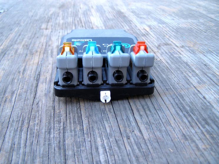
Click to zoom
Application Details
- Equipment Class
- DXX - Part 15 Low Power Communication Device Transmitter
- Date of Grant
- Jan 01, 2008
- Application Purpose
- Original Equipment
- Date of Application
- Jan 01, 2008
- Equipment Note
- TAMI Telemetry System - Transmitter
- Frequency Range
- 916.39000000 - 916.39000000
- Company
- Clinical Innovations
- Country
- United States
Documents & Files
Document Text
Text extracted from the exhibit documents filed with the FCC. Open a document above to read the original.
Users Manual
Instructions for Use Device Description The Tami Trans-Air M ethod of Investigation is a w ireless urodynamic measurement system that receives signals from T-DOC Air-Charged Urodynamic Catheters and transmits them to the urodynamic equipment. This w ireless telemetry system consists of a battery-operated (rechargeable) portable transmitter, a stationary receiver w ith connector cables, and a battery charger. These components w ork together to record accurate urodynamic pressures without water and without wires. Because it is w ireless, TAM I facilitates mobility, including standing and ambulatory st udies, allow ing the pat ient to sit, st and, w alk or heel bounce w ithout concerns of transducer location, rectal balloon adjustments or artifact, or excessive instrumentation. For use in urodynamic recording studies. Indications ® CATHE TER S ® T- DOC, LLC 5 Edgemoor Rd, Suite 212 Wilmington, DE 19809 Phone 302-691-2727 Fax 302-691-6787 Toll Free 866-836-2552 info@ tdocllc.com Urodynamic Procedure Connect receiver cables to urodynamic equipment. Check TAM I rechargeable battery. Check that the cables are connected in proper order, aligning the numbers on the cable w ith the corresponding receiver port. (See Figure 1) Press the blue but ton on the portable transmitter once. If a green blinking light is observed, the battery pow er is adequate. If a red light is observed, the battery needs to be recharged. (See Figure 2) 4 3 2 1 Figure 1 Figure 2 Recharge TAM I battery (w hen necessary). Attach battery charger connector to the side of the portable transmitter. Then, plug the battery charger Figure 3 Attach Check receiver signal. Check the receiver signal by pressing the blue button on the portable transmitter once to get a green blinking light. Then, observe the light s on the stationary receiver connected to the monitoring system. A green light blinking three times means a st rong signal. A green light blinking tw o times means a medium signal. A green light blinking once means a w eak signal. A red light means no signal. A green blinking light, quickly follow ed by a red light means another transmission device might be interfering. (See Figures 1 & 2) Receiver Transmitter Attach catheter(s). Attach the catheter(s) to the portable transmitter by tw isting the colored luer cap(s) onto the transducer connector of the same color. Be sure to completely tighten the luer fittings. (See Figure 4) Attach Transmitter Figure 4 Note: into an electrical outlet. W hen the green light is lit w it hout blinking, the battery is recharged. (See Figure 3) TAM I cannot be used w hen charging. Trans-air method of investigation Attach EM G w ire assembly (optional). Insert catheter(s). If recording EM G signals, connect EM G w ire assembly to transmitter. Attach electrodes to the EM G w ires and position on patient. (See Figure 5) Place cable neck holder around the patient's neck. Insert t he cat het er(s) and perform t he procedure according to hospital protocol. W hen the procedure is complete, uncharge the sensor(s) by sliding the colored sw itch(es)to the open position on t he port able transmitter. Remove catheter(s) and discard. Figure 5 Detachable EM G Ca b l e EM G Ele ctrodes Turn off Portable Transmitter after use. Turn off portable transmitter by holding dow n the blue button for 5 seconds until the green LED light stops blinking. Insert catheter int o the calibrator until each sensor is inside, and then seal calibrator by pushing stopper into t he end of the tube. (See Figure 7) Sensors ( Balloons) Figure 6 Calibrate catheter to system as follow s: Attach catheter(s) to transmit ter. Remove stopper from the end of calibrator, open stopper by pinching tabs, place catheter in slot w ith sensor(s) below the stopper, and release tabs. (See Figure 6) T r a n s - a i r m e t h o d o f i n v e s t i g a t i o n Val v e Catheter Cl o s ed (sealed) Op e n (to atmosphere) Figure 7 Step 6 Charge calibrator to pressure above 50 cmH20 by pumping bulb w ith valve closed. Adjust pressure by lightly pulling back on valve. (See Figure 8) Figure 8 Charge sensor(s) by sliding t he colored transducer sw itch(es) forw ard on the portable transmitter. (See Figure 9) Calibrate according to the urodynamic equipment manufacturer’s instructions. Release pressure from calibrator by pulling valve back until it snaps into place, and remove stopper from calibrator. Charge Figure 9 INSTRUCTION TO THE USER This equipment has been tested and found to comply w ith the limits for a class B digital device, pursuant to part 15 of the FCC Rules. These limits are designed to provide reasonable protection against harmful interference in a residential installation. This equipment generates, uses and can radiate radio frequency energy and if not installed and used in ac cordance w i t h t he i nst ruct i ons, may cause harmful int erf erenc e t o radio comm unic at ions. How ev er, t here is no guarant ee t hat interference w ill not occur in a particular installation. If this equipment does cause harmful interference to radio or television reception, w hich can be determined by turning the equipment off and on, the user is encouraged t o t ry t o correc t t he int erference by one or m ore of t he follow i ng m easures: * Reorient or relocate the receiving antenna. * Increase the separation between the equipment and receiver. * Connect the equipment into an outlet on a circuit different from that to w hich the receiver is connected. * Consult t he dealer or an ex perienc ed radio/ TV t echni ci an for help. This equipment has been certified to comply w ith the limits for a class B computing device, pursuant to FCC Rules. In order to maintain compliance w ith FCC regulations, shielded cables must be used w ith this equipment. Operation w ith non-approved equipment or unshielded cables is likely to result in interference to radio and TV reception. The user is cautioned that changes and modifications made to the e…
Text truncated - open the document above for the full version.
Attestation Statements
1 747 West 4170 South Murray, UT 84123 Phone (801) 268-8200 Fax (801) 266-7373 November 28, 2007 Compatible Electronics TCB 114 Olinda Drive Brea, California 92823 Subject: TCB application submittal Gentlemen: We, Clinical Innovations, LLC, would like to declare that the application being submitted for the device with FCC ID: MWUTAMI, has not been submitted to another TCB for certification. The application was submitted to CETCB on November 28, 2007. If you have any questions, please do not hesitate to contact us at (801) 268-8200. Sincerely, Christopher A. Cutler, Ph.D. Vice President
ID Label/Location Info
091126 TU-4051 T-DOC Company, LLC 5 Edgemoor Road Suite 212 Wilmington, DE 19809 Clinical Innovations, LLC 747 W. 4170 S. Murray, UT 84123 USA P/N 050-0575 Rev. A This device complies with Part 15 of the FCC Rules. Operation is subject to the following two conditions: (1) this device may not cause harmful interference, and (2) this device must accept any interference received, including interference that may cause undesired operation.
Test Report
Report Number: B71011D1 FCC Part 15 Subpart B and FCC Section 15.249 Test Report TAMI Telemetry System Model: TU-4010 Brea Division 114 Olinda Drive Brea, CA 92823 (714) 579-0500 Agoura Division 2337 Troutdale Drive Agoura, CA 91301 (818) 597-0600 Silverado Division 19121 El Toro Road Silverado, CA 92676 (949) 589-0700 Lake Forest Division 20621 Pascal Way Lake Forest, CA 92630 (949) 587-0400 Page 1 of 16 FCC PART 15, SUBPART B and C TEST REPORT for TAMI TELEMETRY SYSTEM MODEL: TU-4010 Prepared for CLINICAL INNOVATIONS, INC. 747 WEST 4170 SOUTH MURRAY, UTAH 84123 Prepared by:_____________________ KYLE FUJIMOTO Approved by:____________________ JAMES ROSS COMPATIBLE ELECTRONICS INC. 114 OLINDA DRIVE BREA, CALIFORNIA 92823 (714) 579-0500 DATE: OCTOBER 18, 2007 REPORT APPENDICES TOTAL BODY A B C D E PAGES 16 2 2 2 15 14 51 This report shall not be reproduced except in full, without the written approval of Compatible Electronics. Report Number: B71011D1 FCC Part 15 Subpart B and FCC Section 15.249 Test Report TAMI Telemetry System Model: TU-4010 Brea Division 114 Olinda Drive Brea, CA 92823 (714) 579-0500 Agoura Division 2337 Troutdale Drive Agoura, CA 91301 (818) 597-0600 Silverado Division 19121 El Toro Road Silverado, CA 92676 (949) 589-0700 Lake Forest Division 20621 Pascal Way Lake Forest, CA 92630 (949) 587-0400 Page 2 of 16 TABLE OF CONTENTS Section / Title PAGE GENERAL REPORT SUMMARY 4 SUMMARY OF TEST RESULTS 4 1. PURPOSE 5 2. ADMINISTRATIVE DATA 6 2.1 Location of Testing 6 2.2 Traceability Statement 6 2.3 Cognizant Personnel 6 2.4 Date Test Sample was Received 6 2.5 Disposition of the Test Sample 6 2.6 Abbreviations and Acronyms 6 3. APPLICABLE DOCUMENTS 7 4. DESCRIPTION OF TEST CONFIGURATION 8 4.1 Description Of Test Configuration - EMI 8 4.1.1 Cable Construction and Termination 9 5. LISTS OF EUT, ACCESSORIES AND TEST EQUIPMENT 10 5.1 EUT and Accessory List 10 5.2 EMI Test Equipment 11 6. TEST SITE DESCRIPTION 12 6.1 Test Facility Description 12 6.2 EUT Mounting, Bonding and Grounding 12 7. TEST PROCEDURES 13 7.1 RF Emissions 13 7.1.1 Conducted Emissions Test 13 7.1.2 Radiated Emissions (Spurious and Harmonics) Test 14 7.1.3 Radiated Emissions (Spurious and Harmonics) Test (Continued) 15 8. CONCLUSIONS 16 Report Number: B71011D1 FCC Part 15 Subpart B and FCC Section 15.249 Test Report TAMI Telemetry System Model: TU-4010 Brea Division 114 Olinda Drive Brea, CA 92823 (714) 579-0500 Agoura Division 2337 Troutdale Drive Agoura, CA 91301 (818) 597-0600 Silverado Division 19121 El Toro Road Silverado, CA 92676 (949) 589-0700 Lake Forest Division 20621 Pascal Way Lake Forest, CA 92630 (949) 587-0400 Page 3 of 16 LIST OF APPENDICES APPENDIX TITLE A Laboratory Recognitions B Modifications to the EUT C Additional Models Covered Under This Report D Diagrams, Charts, and Photos • Test Setup Diagrams • Radiated Emissions Photos • Antenna and Effective Gain Factors E Data Sheets LIST OF FIGURES FIGURE TITLE 1 Plot Map And Layout of 3 Meter Radiated Site Report Number: B71011D1 FCC Part 15 Subpart B and FCC Section 15.249 Test Report TAMI Telemetry System Model: TU-4010 Brea Division 114 Olinda Drive Brea, CA 92823 (714) 579-0500 Agoura Division 2337 Troutdale Drive Agoura, CA 91301 (818) 597-0600 Silverado Division 19121 El Toro Road Silverado, CA 92676 (949) 589-0700 Lake Forest Division 20621 Pascal Way Lake Forest, CA 92630 (949) 587-0400 Page 4 of 16 GENERAL REPORT SUMMARY This electromagnetic emission test report is generated by Compatible Electronics Inc., which is an independent testing and consulting firm. The test report is based on testing performed by Compatible Electronics personnel according to the measurement procedures described in the test specifications given below and in the "Test Procedures" section of this report. The measurement data and conclusions appearing herein relate only to the sample tested and this report may not be reproduced without the written permission of Compatible Electronics, unless done so in full. This report must not be used to claim product endorsement by NVLAP, NIST or any other agency of the U.S. Government. Device Tested: TAMI Telemetry System Model: TU-4010 S/N: N/A Product Description: See Expository Statement Modifications: The EUT was not modified in order to meet the specifications. Customer: Clinical Innovations, Inc. 747 West 4170 South Murray, Utah 84123 Test Date: October 11, 2007 Test Specifications : EMI requirements CFR Title 47, Part 15 Subpart B; and Subpart C, Sections 15.205, 15.209 and 15.249 Test Procedure: ANSI C63.4 Test Deviations: The test procedure was not deviated from during the testing. SUMMARY OF TEST RESULTS TEST DESCRIPTION RESULTS 1 Conducted RF Emissions, 150 kHz – 30 MHz Complies with the Class B limits of CFR Title 47, Part 15, Subpart B. 2 Radiated RF Emissions, 10 kHz – 9300 MHz (Transmitter Portion) Complies with the limits of CFR Title 47, Part 15, Subpart C, section 15.205, 15.209, and 15.249. 3 Radiated RF Emissions, 10 kHz – 9300 MHz (Digital Portion) Complies with the Class B limits of CFR Title 47, Part 15, Subpart B. Report Number: B71011D1 FCC Part 15 Subpart B and FCC Section 15.249 Test Report TAMI Telemetry System Model: TU-4010 Brea Division 114 Olinda Drive Brea, CA 92823 (714) 579-0500 Agoura Division 2337 Troutdale Drive Agoura, CA 91301 (818) 597-0600 Silverado Division 19121 El Toro Road Silverado, CA 92676 (949) 589-0700 Lake Forest Division 20621 Pascal Way Lake Forest, CA 92630 (949) 587-0400 Page 5 of 16 1. PURPOSE This document is a qualification test report based on the Electromagnetic Interference (EMI) tests performed on the TAMI Telemetry System, Model: TU-4010. The EMI measurements were performed according to the measurement procedure described in ANSI C63.4. The tests were performed in order to determine whether the electromagnetic emissions from the equipment under test, referred to as EUT hereafter, are within the Class B specification limits defined by CFR Title 47, Part 15, Subpart B …
Text truncated - open the document above for the full version.
Contact Information
Applicant
Chris Cutler(Senior Vice President of Manufacturing)
Technical Contact
Compatible ElectronicsKyle Fujimoto 114 Olinda Drive
[email protected]714-579-0500
Brea, California · United States
Test Firm
Compatible Electronics, Inc.Ruby Hall
[email protected]805-480-4044
Technical Specifications
| # | Rule Parts | Frequency Range | Power Output |
|---|---|---|---|
| 1 | 15C | 916.39 MHz - 916.39 MHz | - |
Other Applications from Clinical Innovations
MWUIPC5030
Jul 16, 1996Fetal Monitor Receiver
Equipment Class
CYY - Communications Receiver used w/Pt 15 TransmitterMWUIPC5041
Jul 16, 1996Wireless Fetal Monitoring System Transmitter
Equipment Class
DXX - Part 15 Low Power Communication Device Transmitter