
Text extracted from the exhibit documents filed with the FCC. Open a document above to read the original.
Navtrak Mobile Manager ® 904X Installation Guide 050504 For use only with 1XRTT service. i Authorized Installation Guide Table of Contents Section 1: Installation Tools Checklist ......................................................... 1 Section 2: Preparing for Installation ............................................................ 2 Section 3: Bench Testing the Mobile Manager ® .......................................... 3 Section 4: Installing the Mobile Manager ® in Vehicles ................................ 4 Installation Checklist .................................................................. 6 Basic Installation Diagram ......................................................... 7 Power Cable Guide .................................................................... 8 Mobile Manager ® Diagram ......................................................... 9 Pin Layout Defi nition Chart ...................................................... 10 Navtrak Antennas and Order Numbers .................................... 11 Mobile Manager ® Specifi cations ............................................... 12 Note: Changes or modifi cations to the Mobile Manager ® are strictly prohibited and could void the authority to operate equipment. 2 Authorized Installation Guide Section 1: Installation Tools Checklist 1. Navtrak Street Suite ® must be installed on computer with internet access. (If you are an running a older version of the Navtrak Mapping Software, please contact Navtrak Technical Support at 800-787-2337.) Computer Operating System Requirements: ❏ Windows 2000 ❏ Windows XP (Home or Professional Edition) (For other operating systems, contact Technical Support at 800-787-2337.) CPU ❏ Pentium II-based PC 233 MHz or faster Memory ❏ 128MB (256MB recommended) Hard Drive Space ❏ 725MB HD space Monitor ❏ VGA or better display 1024x768 resolution ❏ 8mb video card (16mb recommended) Web Browser ❏ Internet Explorer 6.0 or higher ❏ AOL 8.0 or higher Internet Access ❏ Minimum speed 56 Kbps 2. Be prepared for all bench testing and installations with the following: Bench Utilities: ❏ Navtrak approved antenna ❏ 110VAC to 12 VDC converter ❏ All power cables ❏ Standard RS-232 9-pin serial cable Installation Items: ❏ Voltmeter ❏ Torque Seal ❏ Spare Magnetic Mount antenna ❏ Spare 34-pin Molex Connector 3 Authorized Installation Guide 1. Review your installation plans with the customer to ensure proper antenna type and placement. Keep in mind the antenna has to see the sky, and it cannot be ob- structed by metal objects, (such as ladders stored on vehicle roof). Whenever possible use a tri-band high gain through hole 5/8” bolt antenna (part order #402120). This antenna may also be adapted for mirror, trunk lip, or L-bracket mounting. Note — The antenna must be installed to provide a separation distance of at least 20cm (8 inches) from all persons. The 20cm separation distance from the antenna is required to meet FCC RF exposure com- pliance requirements. 2. Navtrak Mobile Managers should always be mounted in a secure location where LED’s can be read and unit easily removed for service. Section 3: Bench Testing the Mobile Manager ® Section 2: Preparing for Installation Note — Covert Installations 1. Navtrak does not take responsibility for sys- tem performance degradation when using concealed or disguised antennas (covert antennas). 2. If the customer insists on concealing units, they should be advised of possible addi- tional labor costs for upgrades and possible servicing. 3. Navtrak requires customer to sign a release for customer choice of covert antenna and/ or concealed installations. Although Navtrak ships all units programmed and tested, it is highly recommended that each unit is bench tested prior to scheduling installation. 1. Attach GPS and RF data antenna cables. 2. Power up unit. 3. Wait 5 to 10 minutes for the unit to receive GPS satellites position information (acquire GPS lock). 4. Go to www.navtrak.net/partners. 5. Login using your username and password. 6. At the top center of the page select “Bench Test Center”. 7. Select “Vehicle Last Report”. 8. Scroll down and select the new customer to be installed. 9. You can now view the last report for each vehicle. Remember that you are looking at a web page; to view the latest updates, you must refresh your browser. 4 Authorized Installation Guide 1. Mobile Manager ® location Mobile Manager ® should be mounted in a safe area and the LED’s should be easily seen by a service technician or customer. This will as- sist technical trouble shooting, so a customer can tell a remote technician what the LED’s are doing. Note: Concealing the Mobile Manager ® is never a good idea and the customer will have to pay higher technical cost due to the ad- ditional labor required to manage covertly installed units. a. Determine a location in the vehicle that is free of moisture and out of the way. Note: Do not mount unit in the engine compartment. Navtrak recommends mounting the unit in the following areas: 1. Under the seats but away from heat ducts and electric seat motors. 2. In the trunk either on the shelf, under the rear deck, or in a compartment. 3. Under the dashboard or behind the glove box. b. Mount the Mobile Manager ® using ¼ inch screws or tie straps. 2. Antenna placement and mounting a. Navtrak approved antennas must be used. All antennas are available through Navtrak’s distribution center. See page 11 for a list of approved antennas and order information. b. Antennas should be mounted in an open area where the antenna has “good” line- of-site to see the satellites in the sky. Note — The antenna must be installed to provide a separation distance of at least 20cm (8 inches) from all persons. The 20cm separation distance from the antenna is required to meet FCC RF exposure compliance requirements. c. Do not mount any antenna within 6 inches of any metal object that extends above the antenna. This may cause false readings or obstruct line-of-site to satell…
Text truncated - open the document above for the full version.
Navtrak Mobile Manager ® 904X Installation Guide 050504 For use only with 1XRTT service. i Authorized Installation Guide Table of Contents Section 1: Installation Tools Checklist ......................................................... 1 Section 2: Preparing for Installation ............................................................ 2 Section 3: Bench Testing the Mobile Manager ® .......................................... 3 Section 4: Installing the Mobile Manager ® in Vehicles ................................ 4 Installation Checklist .................................................................. 6 Basic Installation Diagram ......................................................... 7 Power Cable Guide .................................................................... 8 Mobile Manager ® Diagram ......................................................... 9 Pin Layout Defi nition Chart ...................................................... 10 Navtrak Antennas and Order Numbers .................................... 11 Mobile Manager ® Specifi cations ............................................... 12 Note: Changes or modifi cations to the Mobile Manager ® are strictly prohibited and could void the authority to operate equipment. 2 Authorized Installation Guide Section 1: Installation Tools Checklist 1. Navtrak Street Suite ® must be installed on computer with internet access. (If you are an running a older version of the Navtrak Mapping Software, please contact Navtrak Technical Support at 800-787-2337.) Computer Operating System Requirements: ❏ Windows 2000 ❏ Windows XP (Home or Professional Edition) (For other operating systems, contact Technical Support at 800-787-2337.) CPU ❏ Pentium II-based PC 233 MHz or faster Memory ❏ 128MB (256MB recommended) Hard Drive Space ❏ 725MB HD space Monitor ❏ VGA or better display 1024x768 resolution ❏ 8mb video card (16mb recommended) Web Browser ❏ Internet Explorer 6.0 or higher ❏ AOL 8.0 or higher Internet Access ❏ Minimum speed 56 Kbps 2. Be prepared for all bench testing and installations with the following: Bench Utilities: ❏ Navtrak approved antenna ❏ 110VAC to 12 VDC converter ❏ All power cables ❏ Standard RS-232 9-pin serial cable Installation Items: ❏ Voltmeter ❏ Torque Seal ❏ Spare Magnetic Mount antenna ❏ Spare 34-pin Molex Connector 3 Authorized Installation Guide 1. Review your installation plans with the customer to ensure proper antenna type and placement. Keep in mind the antenna has to see the sky, and it cannot be ob- structed by metal objects, (such as ladders stored on vehicle roof). Whenever possible use a tri-band high gain through hole 5/8” bolt antenna (part order #402120). This antenna may also be adapted for mirror, trunk lip, or L-bracket mounting. Note — The antenna must be installed to provide a separation distance of at least 20cm (8 inches) from all persons. The 20cm separation distance from the antenna is required to meet FCC RF exposure com- pliance requirements. 2. Navtrak Mobile Managers should always be mounted in a secure location where LED’s can be read and unit easily removed for service. Section 3: Bench Testing the Mobile Manager ® Section 2: Preparing for Installation Note — Covert Installations 1. Navtrak does not take responsibility for sys- tem performance degradation when using concealed or disguised antennas (covert antennas). 2. If the customer insists on concealing units, they should be advised of possible addi- tional labor costs for upgrades and possible servicing. 3. Navtrak requires customer to sign a release for customer choice of covert antenna and/ or concealed installations. Although Navtrak ships all units programmed and tested, it is highly recommended that each unit is bench tested prior to scheduling installation. 1. Attach GPS and RF data antenna cables. 2. Power up unit. 3. Wait 5 to 10 minutes for the unit to receive GPS satellites position information (acquire GPS lock). 4. Go to www.navtrak.net/partners. 5. Login using your username and password. 6. At the top center of the page select “Bench Test Center”. 7. Select “Vehicle Last Report”. 8. Scroll down and select the new customer to be installed. 9. You can now view the last report for each vehicle. Remember that you are looking at a web page; to view the latest updates, you must refresh your browser. 4 Authorized Installation Guide 1. Mobile Manager ® location Mobile Manager ® should be mounted in a safe area and the LED’s should be easily seen by a service technician or customer. This will as- sist technical trouble shooting, so a customer can tell a remote technician what the LED’s are doing. Note: Concealing the Mobile Manager ® is never a good idea and the customer will have to pay higher technical cost due to the ad- ditional labor required to manage covertly installed units. a. Determine a location in the vehicle that is free of moisture and out of the way. Note: Do not mount unit in the engine compartment. Navtrak recommends mounting the unit in the following areas: 1. Under the seats but away from heat ducts and electric seat motors. 2. In the trunk either on the shelf, under the rear deck, or in a compartment. 3. Under the dashboard or behind the glove box. b. Mount the Mobile Manager ® using ¼ inch screws or tie straps. 2. Antenna placement and mounting a. Navtrak approved antennas must be used. All antennas are available through Navtrak’s distribution center. See page 11 for a list of approved antennas and order information. b. Antennas should be mounted in an open area where the antenna has “good” line- of-site to see the satellites in the sky. Note — The antenna must be installed to provide a separation distance of at least 20cm (8 inches) from all persons. The 20cm separation distance from the antenna is required to meet FCC RF exposure compliance requirements. c. Do not mount any antenna within 6 inches of any metal object that extends above the antenna. This may cause false readings or obstruct line-of-site to satell…
Text truncated - open the document above for the full version.
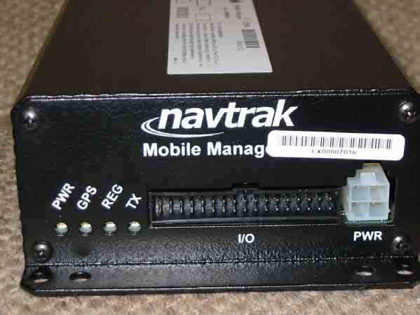
Front Back Right Side Left Side FCC Label
PCB Positioning – Cover Removed Main PCB – Component Side Main PCB – Solder Side GPS PCB – Component Side GPS PCB – Solder Side CDMA PCB – Component ide CDMA PCB – CDMA Module Side
RF Exposure evaluation for FCC ID: MYAMM904Z Part 24E In this mobile application, the RF exposure considerations are identical to those for the incorporated transceiver module FCC ID: OE9Q2438X. A Grant restriction of 6 dBi applies to module antennas. According to 47 CFR 2.1310, the MPE power density limit for the case of General Population exposure in this frequency band is 1 mW/cm 2 . MPE is estimated as: P(mW/cm 2 ) = P(conducted power in mW) x G(numeric antenna gain) 4πr 2 where r = 20 cm, the minimum separation distance for mobile devices. This equation yields, for a measured maximum antenna port power of 265 mW (24.23 dBm) and numeric maximum antenna gain of 4 (6 dBi), an estimated power density of 0.21 mW/cm 2 . This is well below the specified limit.
This report may be reproduced only with the written permission of Intertek and if reproduced must be reproduced in its entirety. This report must not be used to claim product endorsement by NVLAP or any agency of the U.S. Government. The results contained in this report were derived from measurements performed on the identified test samples. Any implied performance of other samples based on this report is dependent on the representative adequacy of the samples tested. TEST REPORT Report Number: 3059176-001 Project Number: 3059176 6/3/2004 Evaluation of the Mobile Manager Model Number: MM904X FCC ID: MYAMM904X FCC Part 2 FCC Part 22 Subpart H FCC Part 24 Subpart E For Formation Inc. Test Performed by: Test Authorized by: Intertek 731 Enterprise Drive Lexington, KY 40510 Formation Inc. 121 Whittendale Drive Moorsetown, NJ 08057 Prepared By:_______________________________Date:____6/3/2004________ Jason Centers, Project Engineer Approved By:______________________________Date:____6/3/2004_________ Bryan C. Taylor, EMC Team Leader Intertek 731 Enterprise Drive, Lexington, KY 40510 731 Enterprise Drive, Lexington KY 40510 Evaluation For:Formation Inc. FCC ID: MYAMM904X Model No: MM904X File: 3059176 Page 2 of 20 FCC Part 2, 22, and 24 Evaluation TABLE OF CONTENTS 1 EXECUTIVE SUMMARY................................................................................................................. 3 2 JOB DESCRIPTION .......................................................................................................................... 4 2.1 CLIENT INFORMATION................................................................................................................. 4 2.2 TEST PLAN REFERENCE: ............................................................................................................... 4 2.3 EQUIPMENT UNDER TEST (EUT) ................................................................................................. 5 2.3.1 System Support Equipment...................................................................................................... 6 2.3.2 Cables associated with EUT ................................................................................................... 6 2.3.3 System Block Diagram ............................................................................................................6 2.3.4 Justification ............................................................................................................................. 7 2.3.5 Mode(s) of operation............................................................................................................... 7 2.4 MODIFICATIONS REQUIRED FOR COMPLIANCE............................................................................ 7 2.5 RELATED SUBMITTAL(S) GRANTS............................................................................................... 7 3 TEST FACILITY................................................................................................................................ 8 4 CONDUCTED RF POWER ..............................................................................................................9 4.1 TEST PROCEDURE........................................................................................................................ 9 4.2 TEST EQUIPMENT......................................................................................................................... 9 4.3 TEST RESULTS............................................................................................................................. 9 5 FIELD STRENGTH OF SPURIOUS RADIATION ..................................................................... 10 5.1 TEST PROCEDURE...................................................................................................................... 10 5.2 TEST EQUIPMENT....................................................................................................................... 10 5.3 TEST RESULTS........................................................................................................................... 11 731 Enterprise Drive, Lexington KY 40510 Evaluation For:Formation Inc. FCC ID: MYAMM904X Model No: MM904X File: 3059176 Page 3 of 20 FCC Part 2, 22, and 24 Evaluation 1 EXECUTIVE SUMMARY Testing was performed for Formation Inc. on the model MM904X Navtrak Mobile Manager. The MM904X contains a CDMA module manufactured by Wavecom (FCCID: O9EQ2438F) which has previously been certified under FCC parts 22 an 24. Since the Wavecom CDMA module has already been certified only the conducted output power and the spurious emission tests were performed on the MM904X. FCC RULE IC RULE DESCRIPTION OF TEST RESULT PAGE §2.1046 RSS-129 §7.1, §9.1 RSS-133 §6.2 RF Power Output Compliant 9 §22.913, §24.232 RSS-129 §7.1, §9.1 RSS-133 §6.2 ERP, EIRP Note 1 - §2.1049 §22.917(b)(d) RSS-129 §6.3, RSS-129 §8.1 Emission Limitation, Occupied Bandwidth Note 1 - §2.1051 §22.917(e) §22.917(f) §24.238(a) RSS-129 §6.3, §7.2.2, §8.1.1, §10 RSS-133 §6.3 Out of Band Emissions at Antenna Terminals Mobile Emissions In Base Frequency Range Note 1 - §2.1053 RSS-129 §8.1 Field Strength of Spurious Radiation Compliant 10 §2.1091, §2.1093 RSS-129 §11, RSS-133 §8 Specific Absorption Rate NA See Note 2 §15.107, §15.207 IC ES-003 Power Line Conducted Emissions Note 1 - §15.109 IC ES-003 RSS-129 §10, RSS-133 §9 Receiver Spurious Emission Note 1 - §2.1055, §22.355, §24.235 RSS-133 §7 Frequency Stability vs. Temperature Note 1 - §2.1055, §22.355, §24.235 -- Frequency Stability vs. Voltage Note 1 - N/S: Not under scope of this evaluation 1 Evaluation of the MM904X to this criteria was not performed. Results from the Wavecom CDMA module (FCC ID: O9EQ2438F) filing will be used to determine compliance. 2 Specific Absorption Rate testing was not under the scope of this evaluation. 731 Enterprise Drive, Lexington KY 40510 Evaluation For:Formation Inc. FCC ID: MYAMM904X Mode…
Text truncated - open the document above for the full version.
Test Setup – Radiated Emissions Test Setup – Conducted Power Measurements
121 Whittendale Drive · Moorestown, New Jersey · United States
| # | Rule Parts | Frequency Range | Power Output | Emission | Tolerance |
|---|---|---|---|---|---|
| 2 | 22H | 824.7 MHz - 848.31 MHz | 231.00 mW | 1M28F9W | 2.5 ppm |
JBP - Part 15 Class B Computing Device Peripheral
Equipment Class
JBP - Part 15 Class B Computing Device Peripheral