N2K-2540HBData Transceiver
Keylogic NV
Click to zoom
Application Details
- Equipment Class
- DXT - Part 15 Low Power Transceiver, Rx Verified
- Date of Grant
- Jan 10, 1999
- Application Purpose
- Original Equipment
- Date of Application
- Oct 22, 1998
- Equipment Note
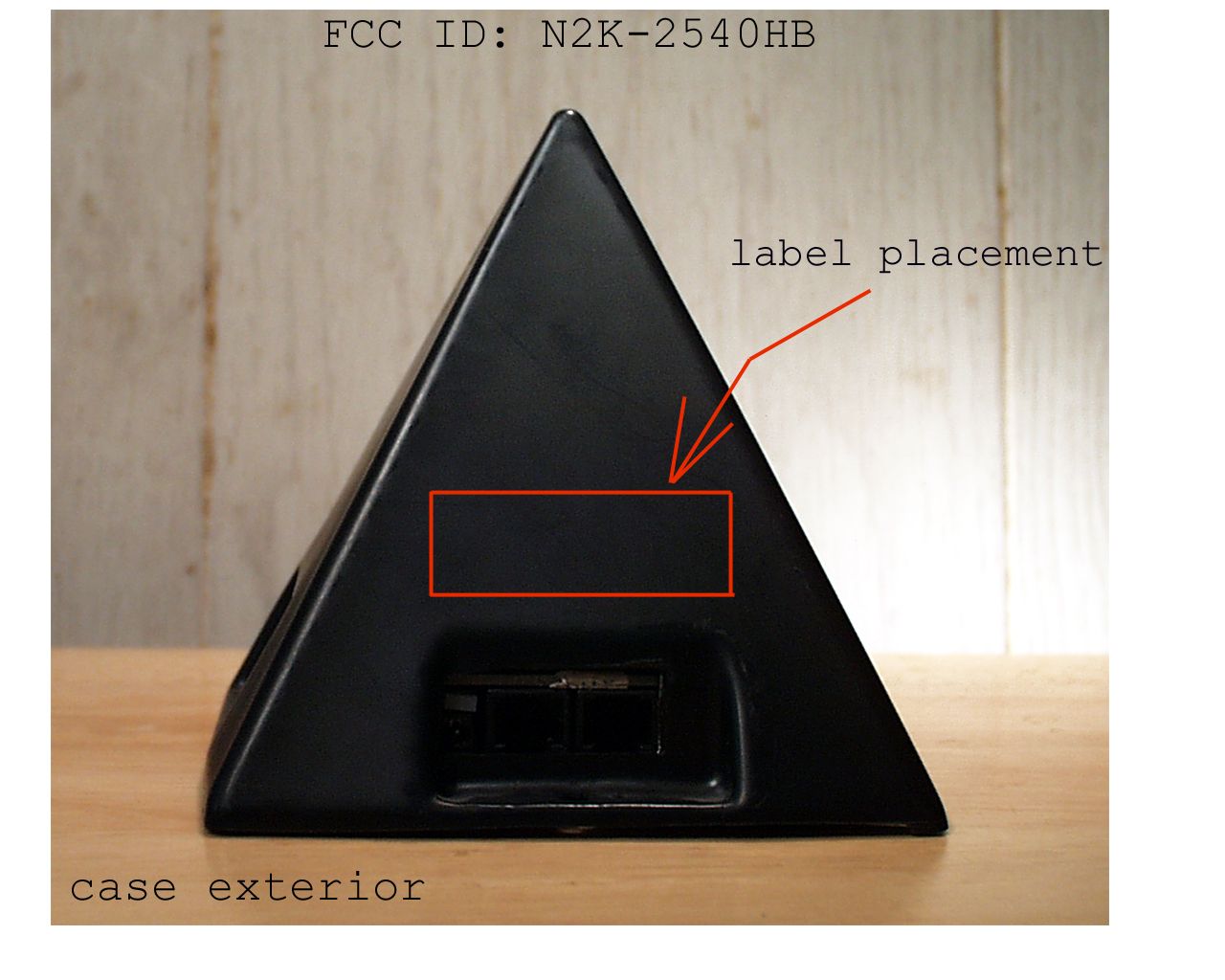
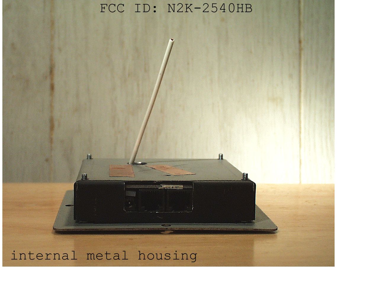
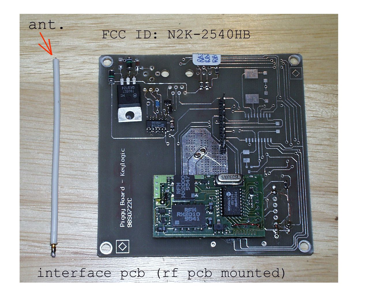
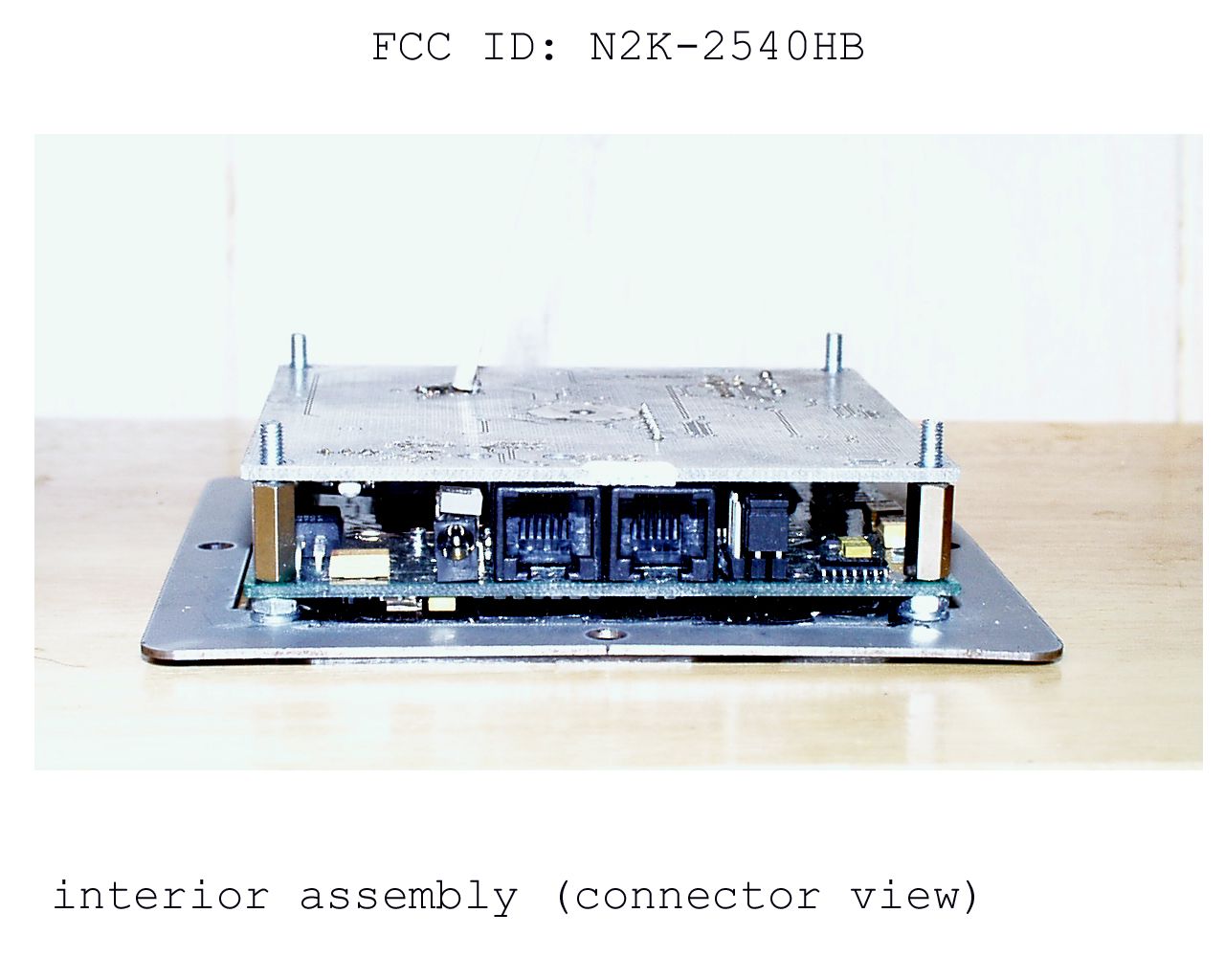
- Data Transceiver
- Frequency Range
- 916.30000000 - 916.80000000
- Company
- Keylogic NV
- Country
- Belgium
Documents & Files
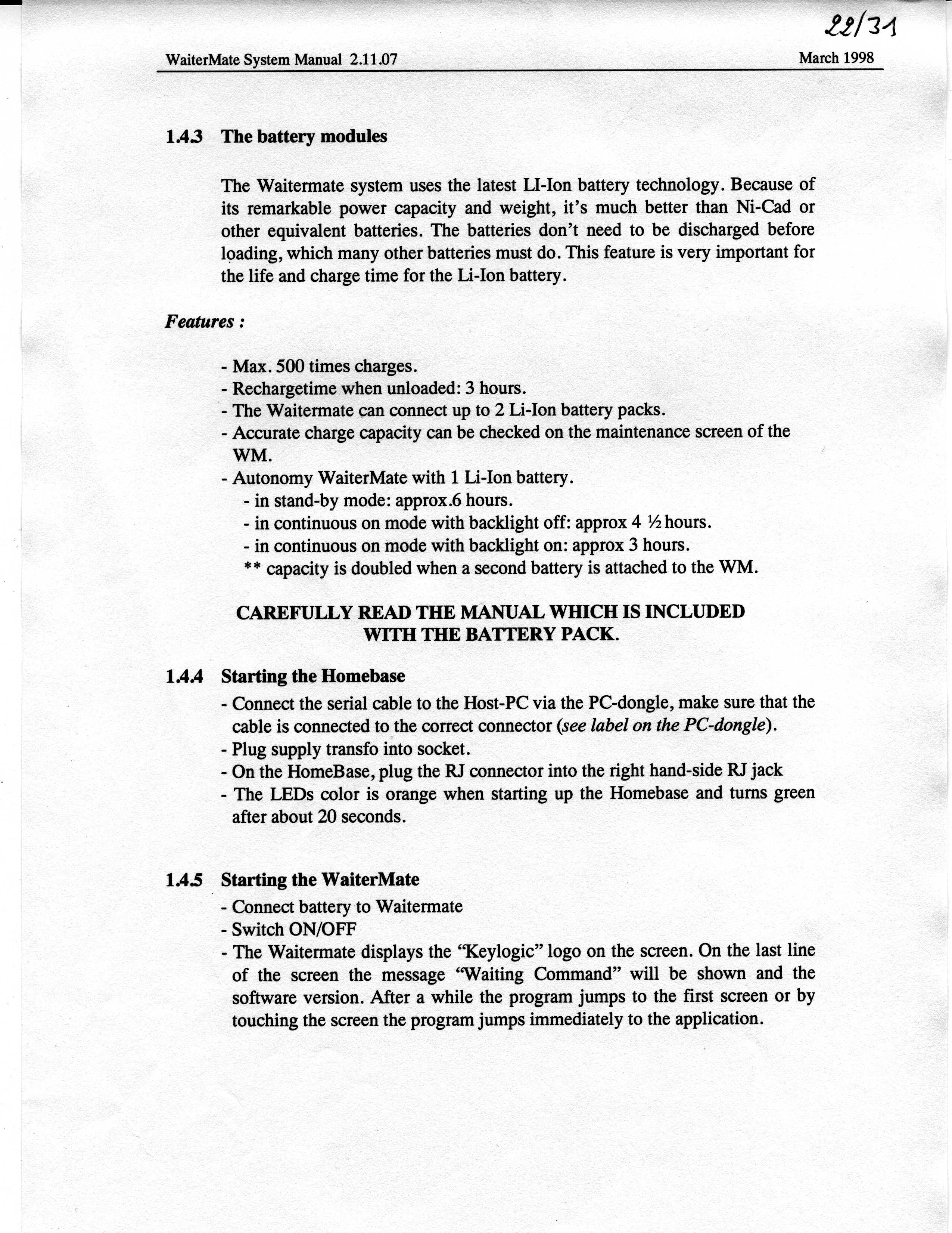
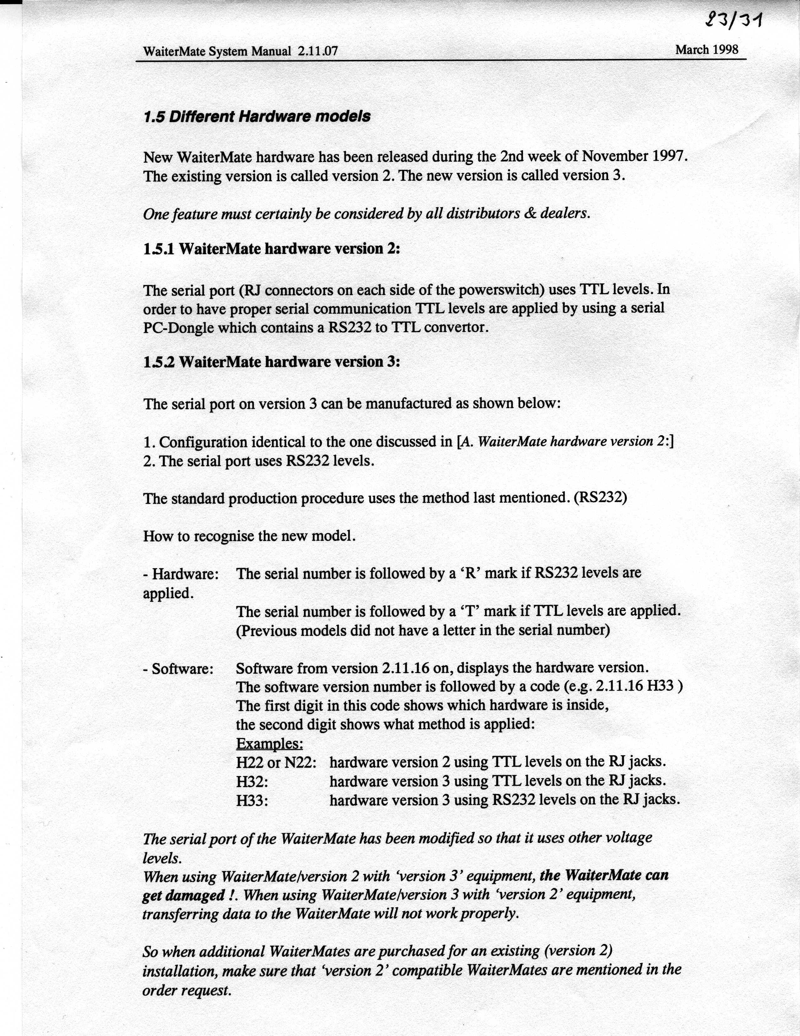
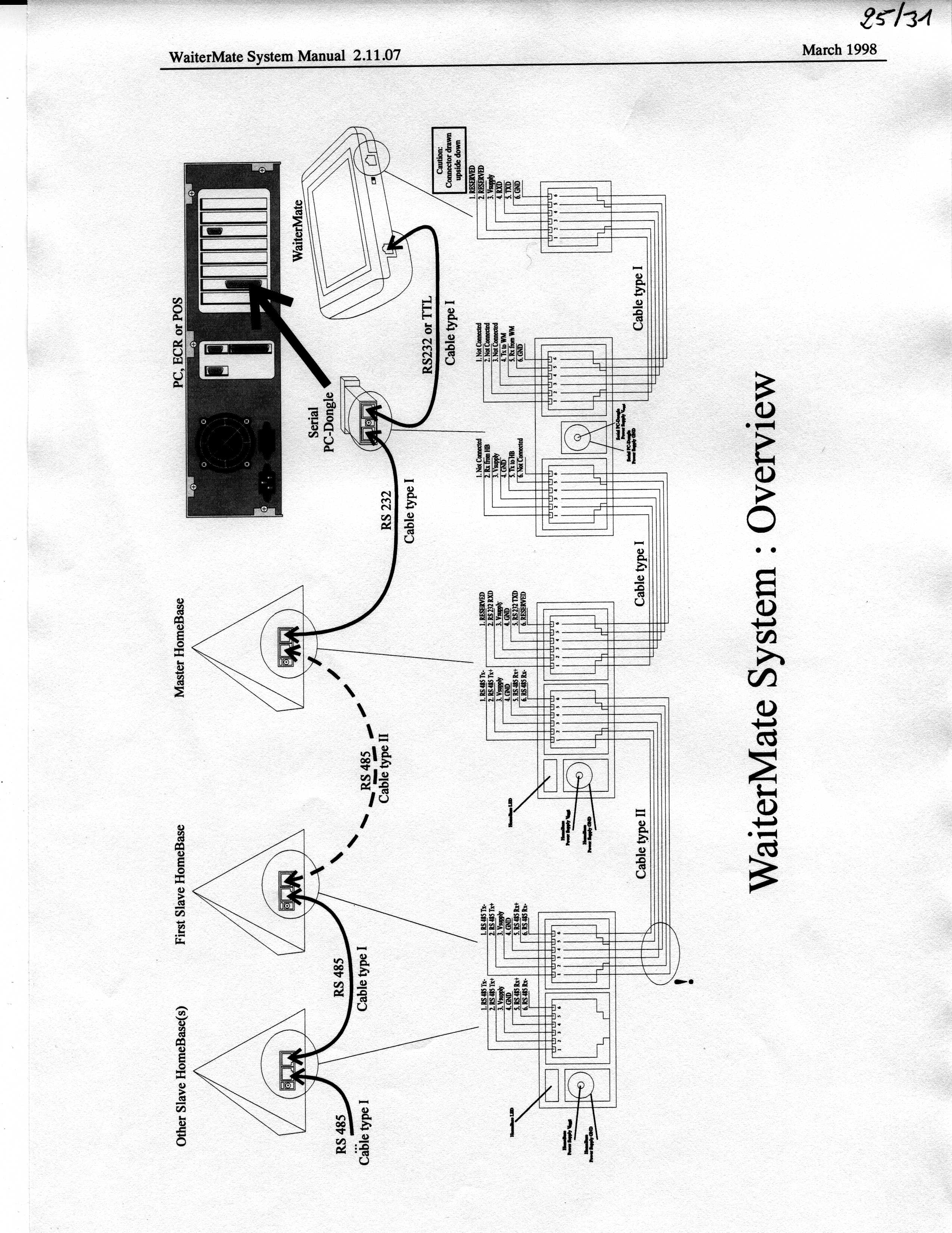
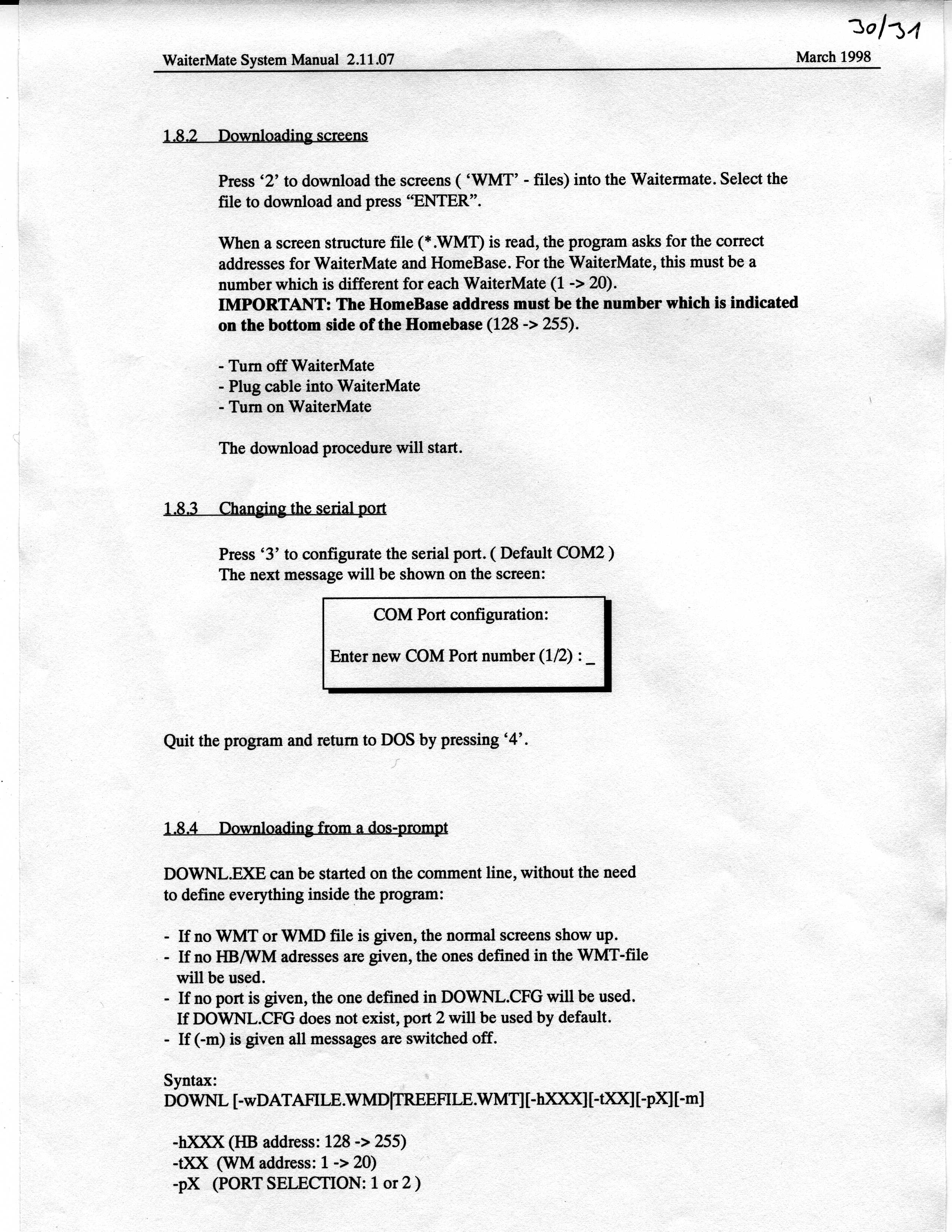
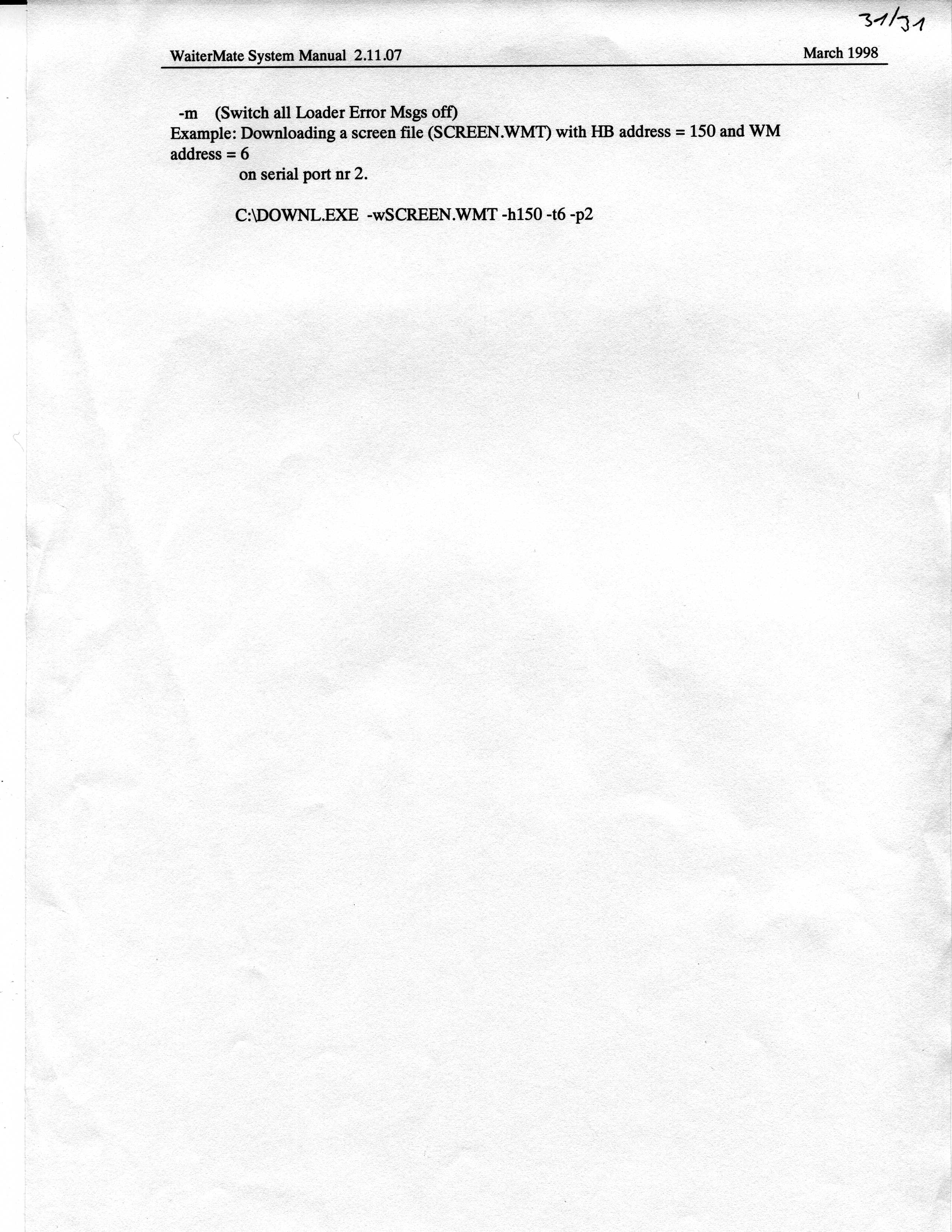
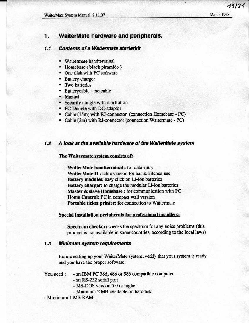


Document Text
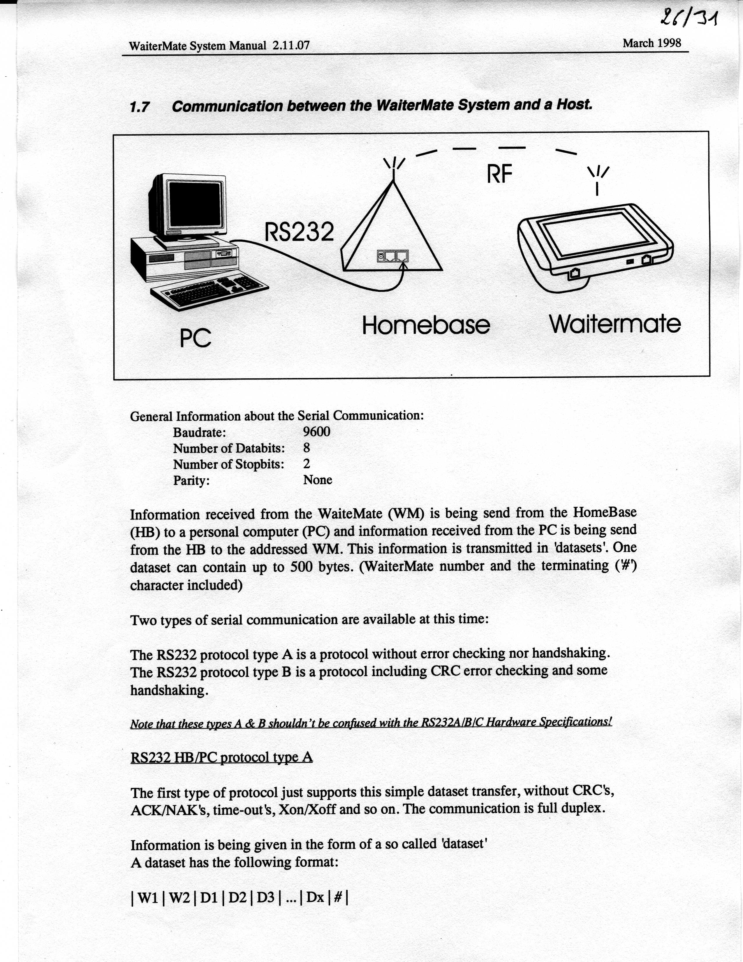
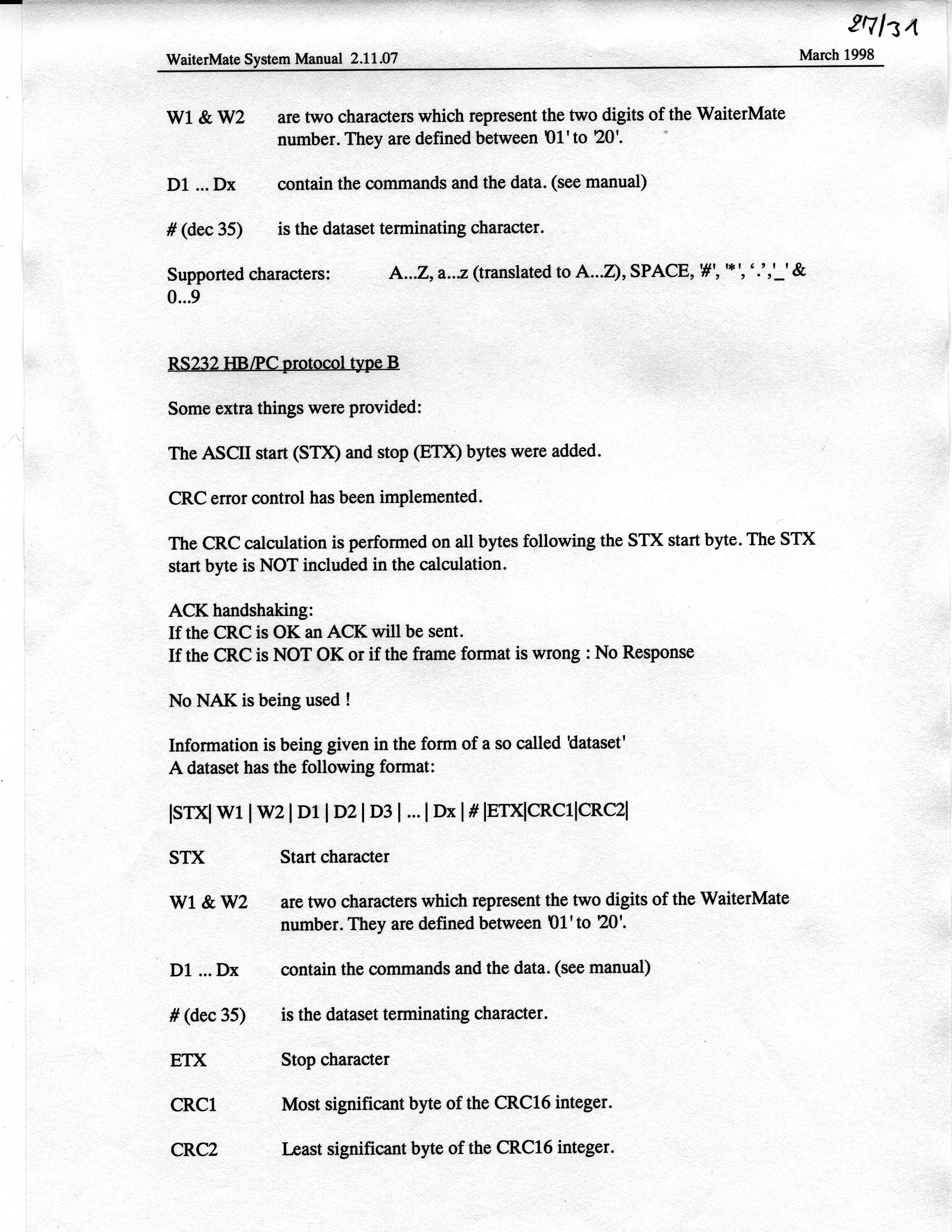
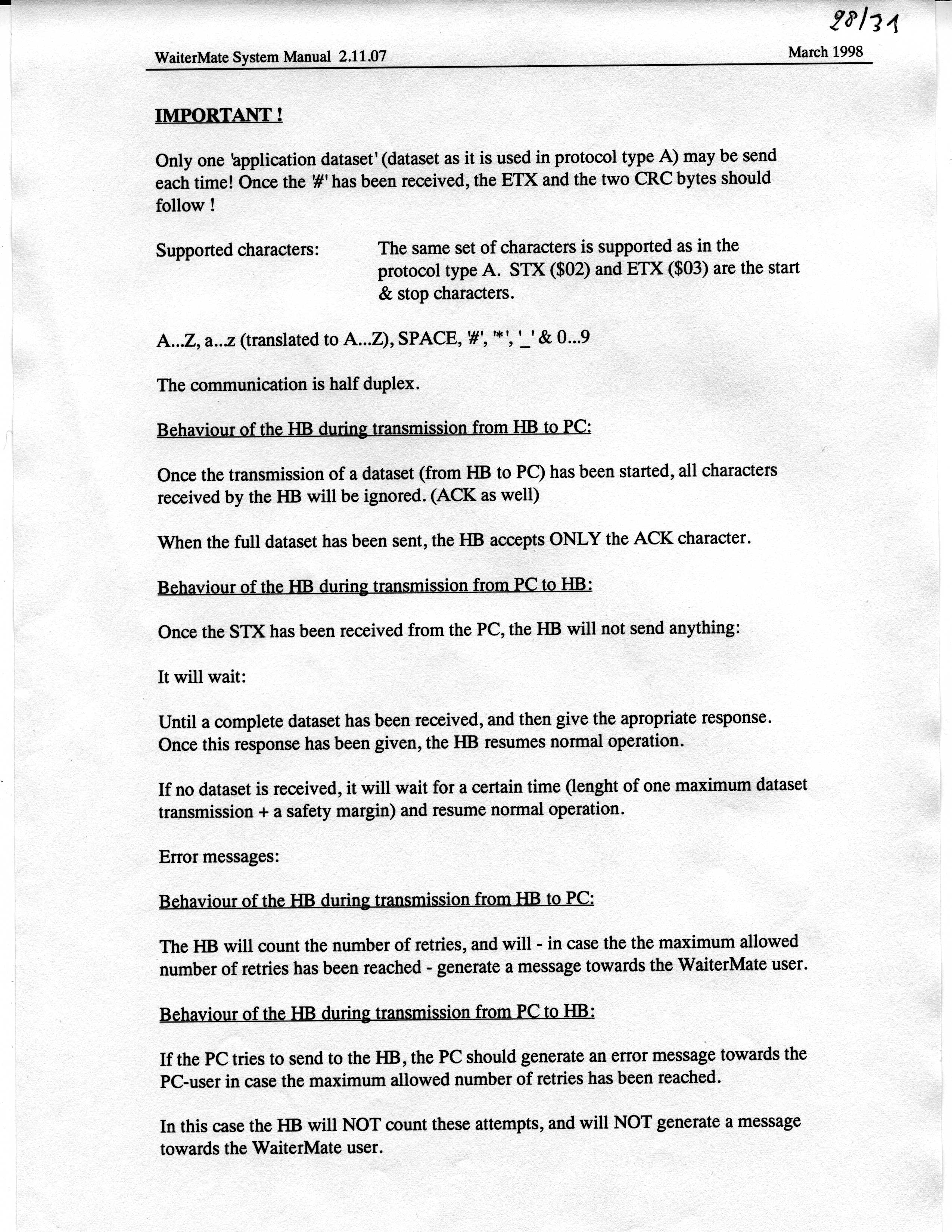
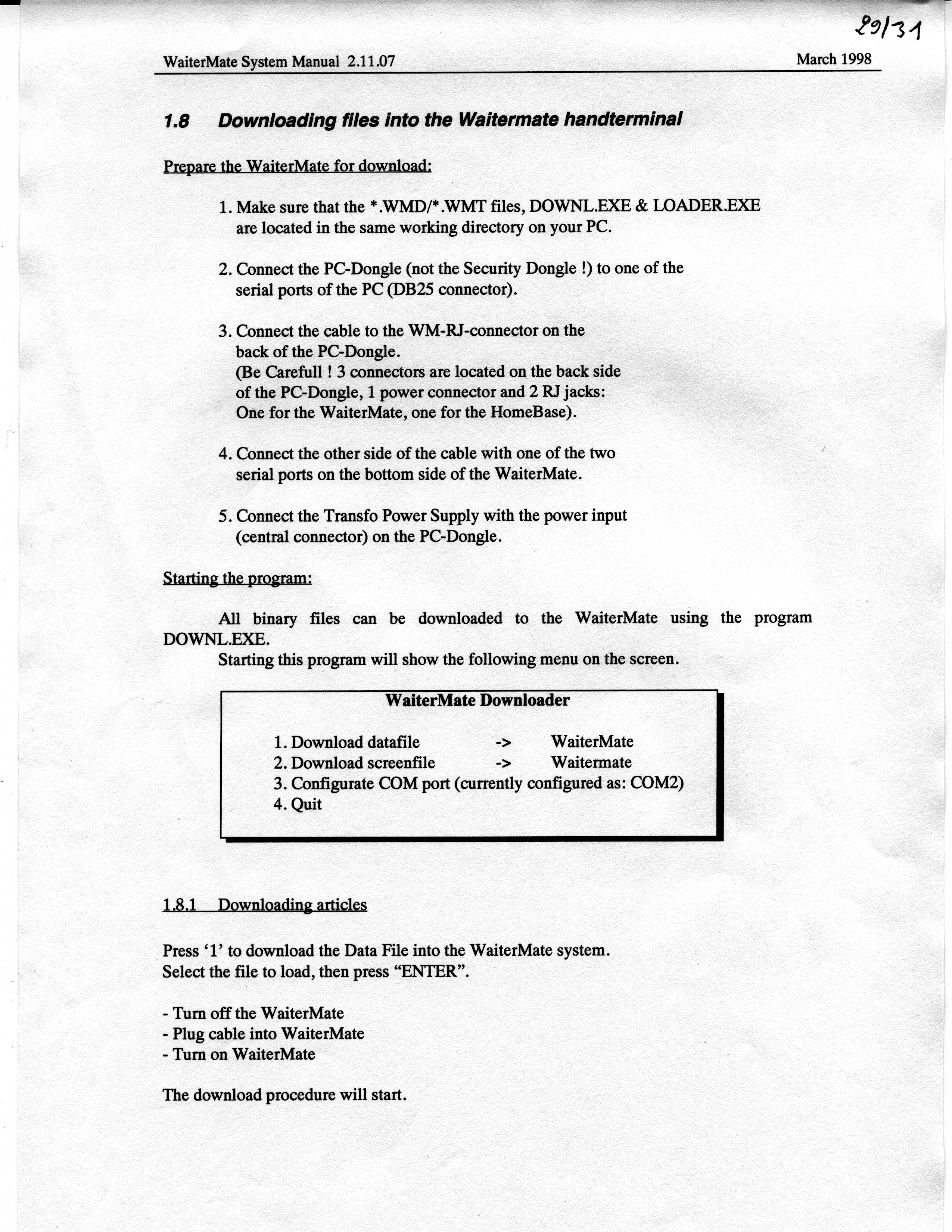
Text extracted from the exhibit documents filed with the FCC. Open a document above to read the original.
Cover Letter(s)
July 9, 2001 Federal Communications Commission Laurel, MD Dear Mr. Lobel: The client applicant for this product has requested that the following items be held in confidence by the Commission: 1. Schematics 2. Circuit description 3. Block diagrams The request is made to protect some of the unique features of this product that may cause harm to the client’s sales program if the information is released to the public before it launches its marketing campaign this coming spring. On behalf of Keylogic NV; thank you for your consideration of this request. Respectfully, Thomas W. Roche Control Design & Testing 6010 Red Fox Drive Spotsylvania, VA 22553
Test Report
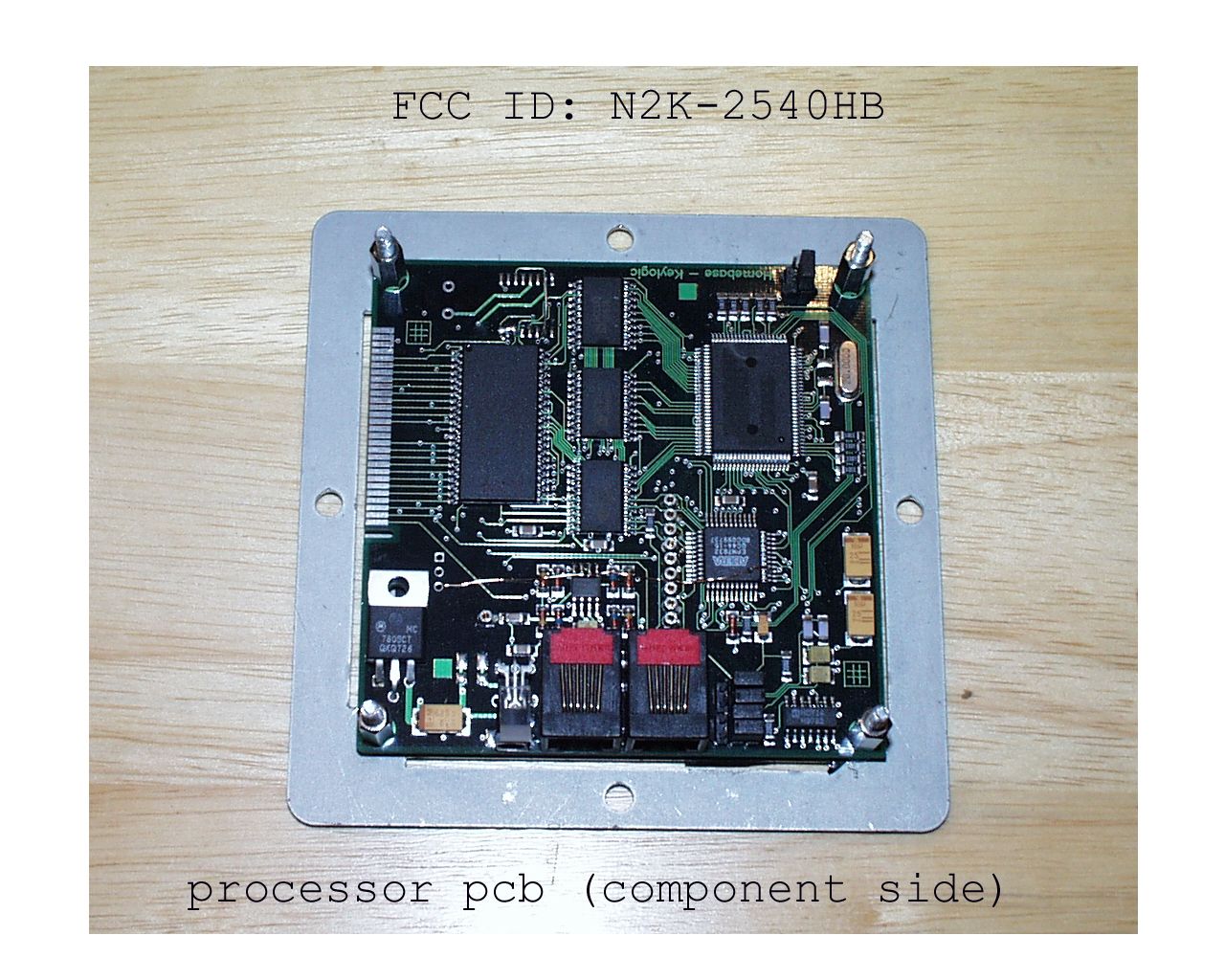
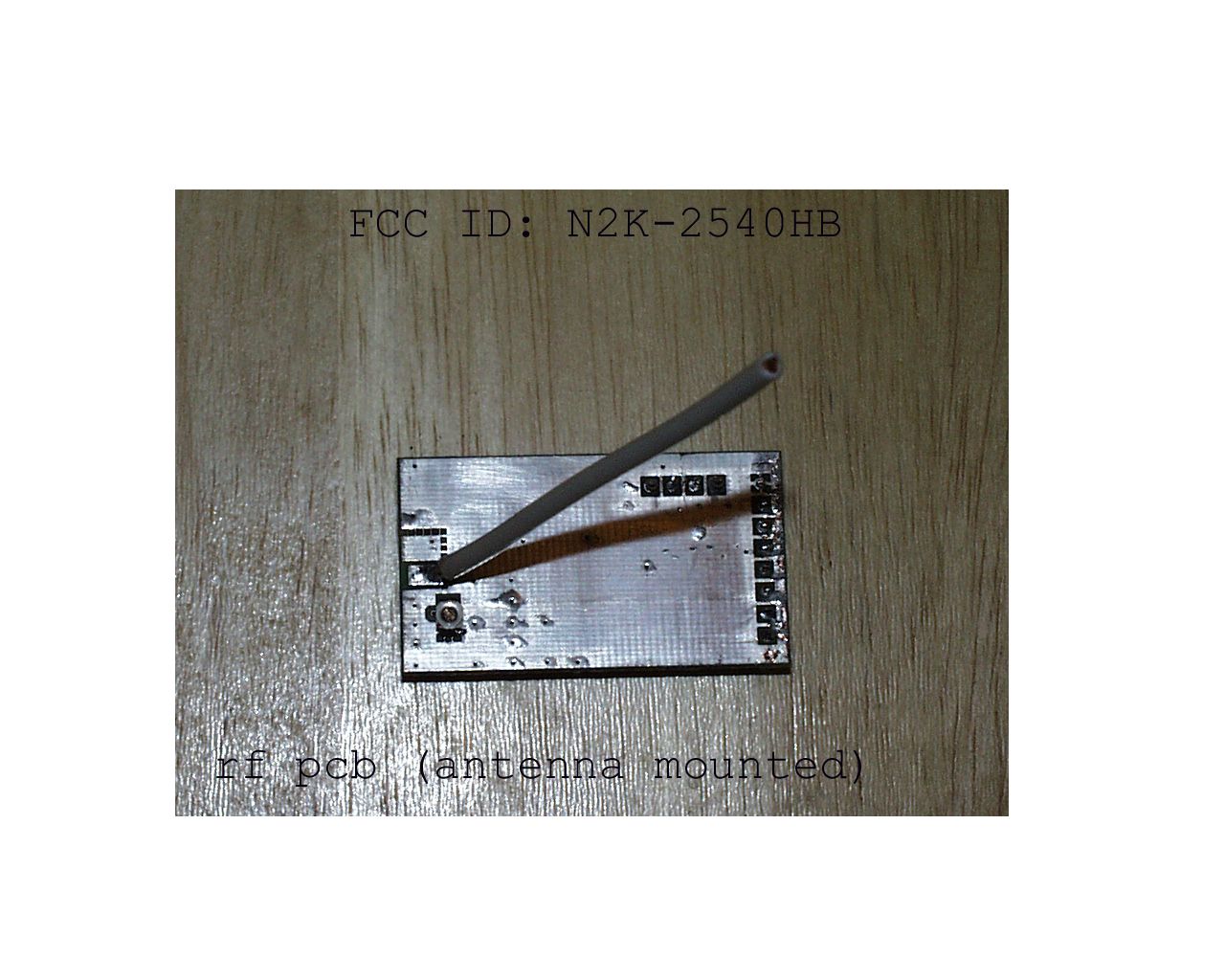
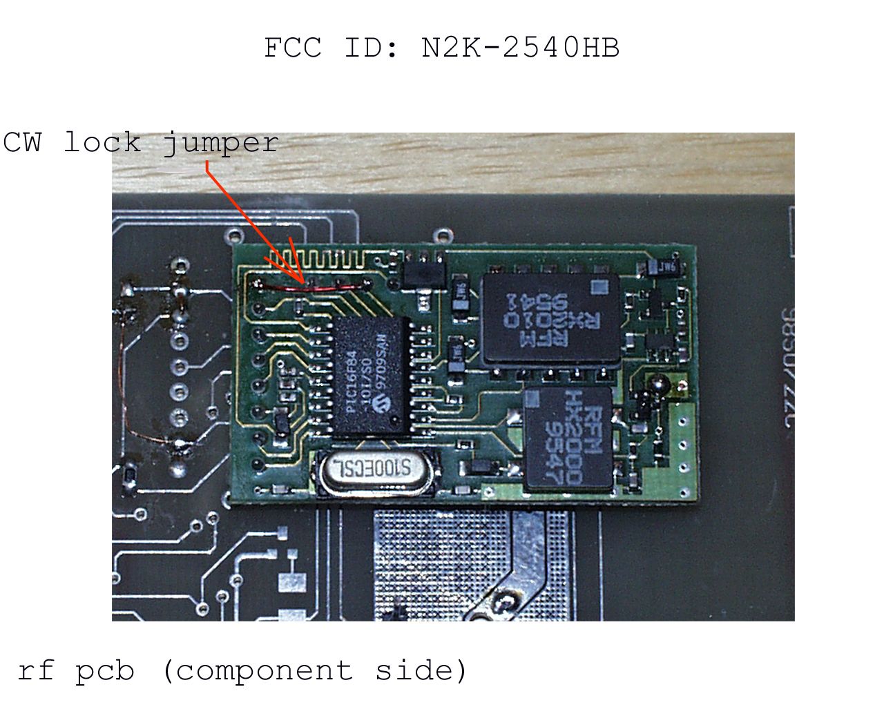
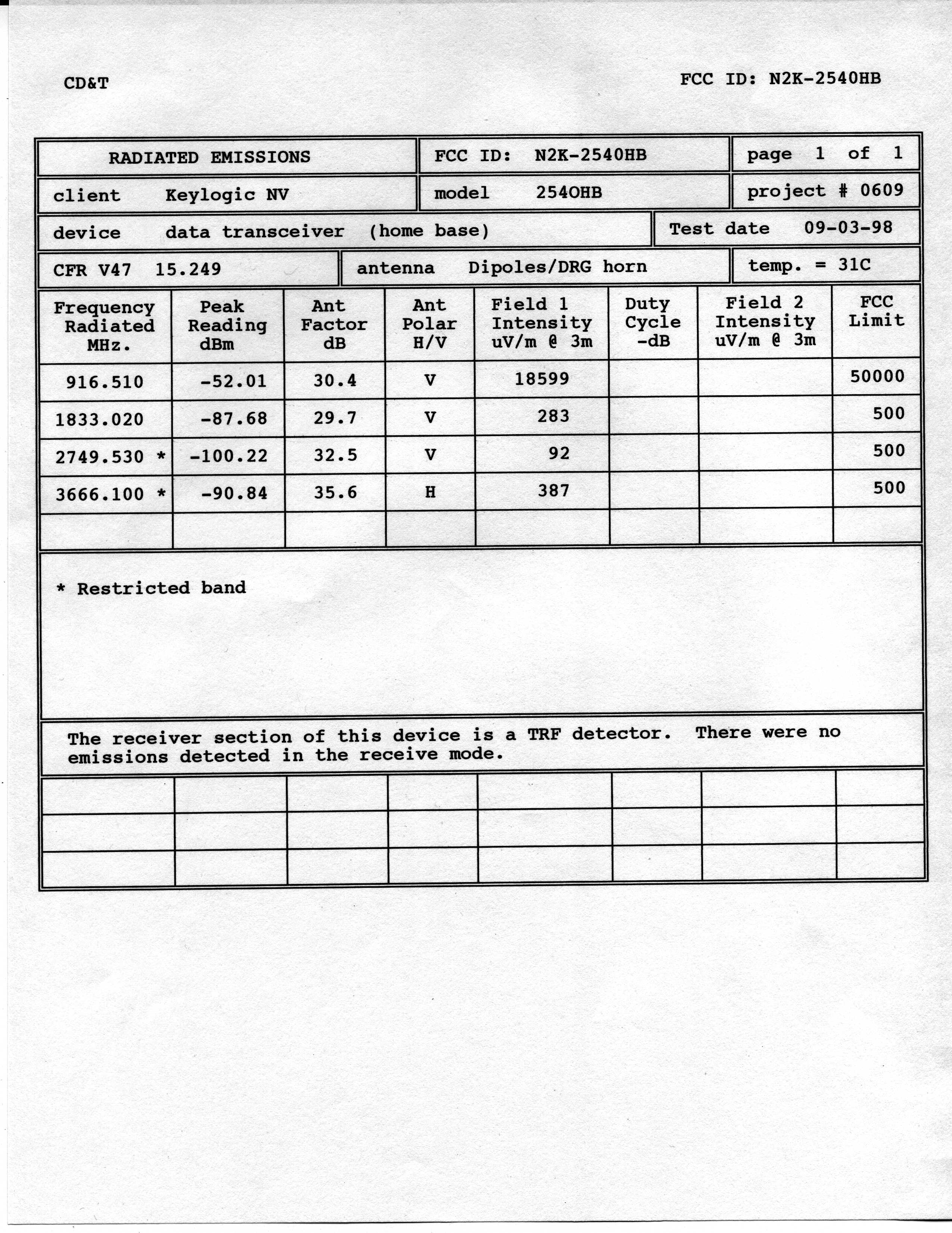
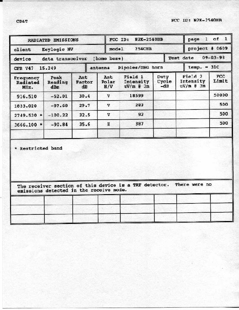
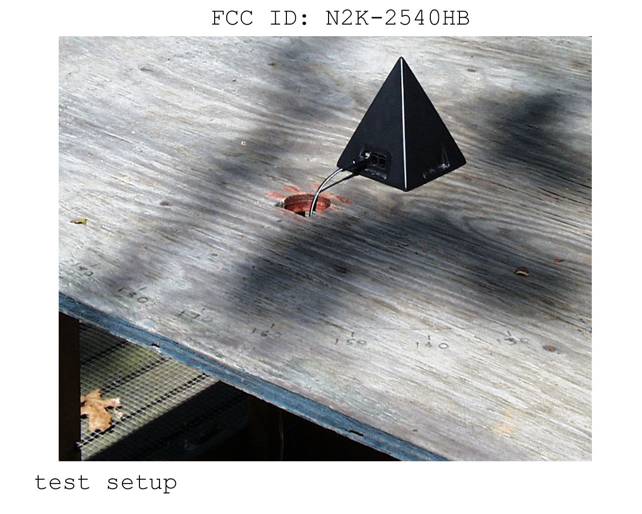
CD&T FCC ID: N2K-2540HB A. DEVICE UNDER TEST The device is a low power data transceiver operating under the provisions of Part 15.249 of the FCC rules. The transmit and receive frequencies are the same, operating in simplex mode at 916.5MHz. nominal. The modulation mode is on/off keying at rates up to 14400 baud. The receiver section is a TRF type using sequentially tuned amplifier stages that are clocked at a nominal 245kHz. No signals relating to the receiver clock frequency were detectable as radiated emissions. B. MEASUREMENT PROCEDURE: RADIATED EMISSIONS Transmitter field strength measurements were conducted according to the procedures set forth in ANSI C63.4 (1992). The device under test was placed on a rotating turntable 0.8 meters high, centered at 3 meters distant from the measurement antenna. The device was placed in the center of the turntable and tested in the position as shown in the photograph. This housing is designed to sit flat as shown and has no provisions for mounting in any other position. The device is powered from an external 12VDC plug-in wall and is internally regulated at 5V. The test was conducted with the supply transformer plugged into a standard 115VAC wall outlet built into the base of the turntable and connected to the mains through slip rings mounted under the turntable base. For the purposes of testing, the device was locked in a constant transmit mode (CW) by tying the data input line to the positive rail. The field strength measurements were taken using an HP8596E spectrum analyzer, EMCO 3121C dipole set, an EMCO 3115 double ridge guide horn and an Avantek UJ210 preamp. The device was scanned from 30MHz. to 9.2GHz. and all emissions were noted. In this case the only emissions detected were those harmonically related to the fundamental transmit frequency. At each detected frequency of emission, the device was measured by rotating the turntable and adjusting the antenna height over a range of 1 to 4 meters to obtain the maximum output level. This procedure was performed with both horizontal and vertical antenna polarizations with the device in the positions described above. The peak reading for each frequency was recorded in the second column on the data sheet. Scanning for emissions above the 4 th harmonic was performed by reducing the distance from the measurement antenna to 1 meter. Harmonics above the 4 th were not detectable. The calculations for this device were made without factoring in a duty cycle correction factor. Although the transmission mode is on/off keying and yields a correction factor of approximately -8dB., all emissions were sufficiently below the applicable limits to ignore the offset.
Contact Information
Applicant
Mike Straub Biltris(President)
32-050-316715
Technical Contact
Same as above
[email protected]540-582-2826
Non-Technical Contact
Same as above
[email protected]540-582-2826
Test Firm
Hyak Laboratories, Inc.Rowland Johnson
703-451-1188
Technical Specifications
| # | Rule Parts | Frequency Range | Power Output |
|---|---|---|---|
| 1 | 15C | 916.3 MHz - 916.8 MHz | - |
Other Applications from Keylogic NV

N2K-2540HH
Jan 10, 1999Data Transceiver
Equipment Class
DXT - Part 15 Low Power Transceiver, Rx Verified