N2OTEL2RADIO456Radio Data Transmitter
Ellab Monitoring Solutions Ltd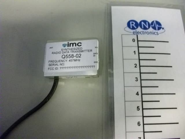
Click to zoom
Application Details
- Equipment Class
- TNB - Licensed Non-Broadcast Station Transmitter
- Date of Grant
- Nov 28, 2012
- Application Purpose
- Original Equipment
- Date of Application
- Nov 28, 2012
- Equipment Note
- Radio Data Transmitter
- Frequency Range
- 457.60000000 - 457.60000000
- Country
- United Kingdom
Documents & Files
Document Text
Text extracted from the exhibit documents filed with the FCC. Open a document above to read the original.
Users Manual
User Guide – TEL2RADIO457 UHF Narrow band transceiver module TEL2RADIO457 Version 1.2 The IMC Group Ltd, Pendle House Jubilee Road Letchworth Hertsfordshire SG6 1SP United Kingdom Tel: +44(0)1462 688070 Fax: +44(0)1462688071 e-mail: [email protected] User Guide – TEL2RADIO457 GENERAL DESCRIPTION & FEATURES Features FCC Part 90 (transmitter) and Part 15 compliant (receiver) 10 mW output power Single channel 457.6 MHz High sensitivity receiver FM narrow band modulation Applications Telemetry systems General description The TEL2RADIO457 is a RoHS compliant FCC approved embedded industrial Narrow band FM radio transceiver. SPECIFICATIONS General specification * All values are specified with 50 ohm terminal and at 25 °C +/- 10 °C and are typical unless otherwise noted. Communication method One-way Operating frequency range MHz 457.6 MHz band Operation temperature range °C -10 to 60 No dew condensation Storage temperature range °C -30 to 70 No dew condensation Aging rate ppm +/- 1 / year TX freq., RX Lo freq. -1 1 Initial frequency tolerance ppm +/- 5 TX/RX freq. Dimensions 36mm x 36mm x 5mm Weight 25g Electrical specification Common to TX/RX Channel span 12.5kHz Number of channels 1 Maximum Data rate bps 2400 Antenna impedance is 50 (Nominal) Operating voltage 3.0V to 3.6V. TX consumption current 36mA @ 10mW VCC=3.0V RX consumption current 24mA VCC=3.0V Transmitter RF output power 10mW (maximum) Deviation kHz ± 2.1 Receiver Max. Input level 10dBm Sensitivity -120dB Data Port The Data port is design for digital signals only and the maximum data rate is 2400 baud. A logic 0 is any voltage less than 0.8volt and a logic 1 is any voltage above 2.4volts up to 3.6volts. The input impedance of this port is >1Mohm. User Guide – TEL2RADIO457 PIN DESCRIPTION Receiver/Transmitter GND DI/DO – Digital input (receiver) DO (transmitter) VCC Antenna connected via SMA connector and RF Screened cable ANTENNAS A 1/4 wave antenna with a gain of less than 2.1dBi suitable for 457Mhz operation should be used with the TEL2RADIO457 Radio module to ensure correct and reliable operation. Notice: Use the antenna recommended as other antennas may invalidate compliance with the regulatory standards. Regulatory compliance information WARNING: This module needs to have a License to comply with FCC Rules, please contact the IMC Group for further information. This device complies with Part 15 of the FCC Rules. Operation is subject to the following two conditions: (1) This device may not cause harmful interference, and (2) this device must accept any interference received, including interference that may cause undesired operation. Caution: Any changes or modifications not expressly approved by the party responsible for product compliance could void the user's authority to operate the equipment. Caution Exposure to radio frequency radiation: To comply with FCC RF exposure compliance requirements, a separation distance of at least 20 cm must be maintained between the antenna of this device and all persons. This device must not be co-located or operating in conjunction with any other antenna or transmitter. Labeling: The IMC Group Ltd transmitter/Receiver module TEL2RADIO457 labeled as below. FCC ID: The proposed FCC ID label format is to be placed on the module. If FCC ID is not visible when the module is installed into the system, the label should be placed on the outside of final host system "Contains FCC ID: N20TEL2RADIO456". IC ID: The proposed IC ID label format is to be placed on the module. If IC ID is not visible when the module is installed into the system, "Contains IC: 10310A-T2RADIO456" shall be placed on the outside of final host system. Cautions As the radio module communicates using electronic radio waves, there are cases where transmission will be temporarily cut off due to the surrounding environment and method of usage. The manufacturer is exempt from all responsibility relating to resulting harm to personnel or equipment and other secondary damage. Do not use the equipment within the vicinity of devices that may malfunction as a result of electronic radio waves from the radio module. The manufacturer is exempt from all responsibility relating to secondary damage resulting from the operation, performance and reliability of equipment connected to the radio module. Communication performance will be affected by the surrounding environment, so communication tests should be carried out before actual use. User Guide – TEL2RADIO457 Ensure that the power supply for the radio module is within the specified rating. Short circuits and reverse connections may result in overheating and damage and must be avoided at all costs. Ensure that the power supply has been switched off before attempting any wiring work. The case is connected to the GND terminal of the internal circuit, so do not make contact between the '+' side of the power supply terminal and the case. Do not use this equipment in vehicles with the windows closed, in locations where it is subject to direct sunlight, or in locations with extremely high humidity. The radio module is neither waterproof nor splash proof. Ensure that it is not splashed with soot or water. Do not use the equipment if water or other foreign matter has entered the case. Warnings Do not take a part or modify the equipment. Do not remove the product label (the label attached to the upper surface of the module.) Using a module from which the label has been removed is prohibited. This device complies with part 15 of the FCC Rules. Operation is subject to the condition that this device does not cause harmful interference. The IMC Group Ltd All right reserved No part of this document may be copied or distributed in part or in whole without the prior written consent of The IMC Group Ltd. REVISION HISTORY N/A
External Photos
External Photographs.
ID Label/Location Info
Ink is a high performance pure resin Label material is 8100HT White Polyester
Internal Photos
Internal photograph
Test Report
Radio Test Report FCC 47CFR90.217 For 457MHz radio module TEL2RADIO457 Reference Standard: FCC 47CFR90.271 Oct ‘11 Manufacturer: The IMC Group Ltd For type of equipment and serial number, refer to section 3 Report Number: 04-559/4998/1/12 Report Produced by: - R.N. Electronics Ltd. 1 Arnolds Court Arnolds Farm Lane Mountnessing Essex CM13 1UT U.K. www.RNelectronics.com Telephone +44 (0) 1277 352219 Email [email protected] electronics R N 2012 RN ELECTRONICS LIMITED REPORT NUMBER 04-559/4998/1/12 ALL RIGHTS RESERVED File name IMC GROUP LTD.4998.1.DOCX The contents of this report are beyond the scope of UKAS Testing Laboratory No. 2360 accreditation. QMF21J – 3; FCC47CFR90.217; RNE ISSUE 01, JUL 2012 PAGE 2 OF 24 Copy No. pdf Arnolds Court, Arnolds Farm Lane, Mountnessing, Brentwood Essex, CM13 1UT Certificate of Test 4998/1 The unit noted below has been tested by R.N. Electronics Limited and, where appropriate, conforms to the relevant subpart of FCC 47CFR90.217. This is a certificate of test only and should not be confused with an equipment authorization. Other standards may also apply. Equipment: 457MHz radio module Model Number: TEL2RADIO457 Proposed FCC ID: N20TEL2RADIO456 Unique Serial Number: W1 Manufacturer: The IMC Group Ltd Suite 6 24 Swan Street Kingsclere Newbury Berkshire RG20 5PJ UK Customer Purchase Order Number: 406662 Full measurement results are detailed in Report Number: 04-559/4998/1/12 Test Standards: FCC 47CFR90.217, Oct 2011 Licensed Non-Broadcast Transmitter; Class TNB NOTE: Certain tests were not performed based upon manufacturer's declarations. Certain other requirements are subject to manufacturer declaration only and have not been tested/verified. For details refer to section 3 of this report. DEVIATIONS: None. This certificate relates only to the unit tested as identified by a unique serial number and in the condition at the time it was tested. It does not relate to any other similar equipment and performance of the product before or after the test cannot be guaranteed. W hilst every effort is made to assure quality of testing, type tests are not exhaustive and although no non-conformances may be found, this doesn't exclude the possibility of unit not meeting the intentions of the standard or the requirements of the Federal Regulations, particularly under different conditions to those during testing. Any compliance statements are made reliant on (a) the application of the product and use of the assigned band being acceptable to the FCC and (b) the modes of operation as instructed to us by the Customer based on their specific knowledge of the application and functionality of the EUT. Statements of compliance, where measurements were made, do not include the measurement uncertainty. The measurement uncertainty, where stated, is the expanded uncertainty based on a standard uncertainty multiplied by a coverage factor of k=2, providing a level of confidence of approximately 95%. Date of Test: 19th - 20th April 2012 Test Engineer: Peter Finley Approved By: Technical Director Customer Representative: electronics R N 2012 RN ELECTRONICS LIMITED REPORT NUMBER 04-559/4998/1/12 ALL RIGHTS RESERVED File name IMC GROUP LTD.4998.1.DOCX The contents of this report are beyond the scope of UKAS Testing Laboratory No. 2360 accreditation. QMF21J – 3; FCC47CFR90.217; RNE ISSUE 01, JUL 2012 PAGE 3 OF 24 1. Contents 1. Contents .............................................................................................................. 3 2. Summary of test results ........................................................................................ 4 3. Equipment Under Test (EUT) ............................................................................... 5 3.1 EQUIPMENT GENERAL SPECIFICATION ............................................................................................... 5 3.2 EQUIPMENT RF PARAMETERS AND CONFIGURATIONS FOR TESTING .................................................. 5 3.3 FUNCTIONAL DESCRIPTION OF EUT .................................................................................................. 6 3.3 EUT MODES ...................................................................................................................................... 6 3.4 EMISSIONS CONFIGURATION ............................................................................................................. 7 4. Specifications ....................................................................................................... 8 4.1 RELEVANT STANDARDS .................................................................................................................... 8 4.2 DEVIATIONS ...................................................................................................................................... 8 4.3 TEST SITE .......................................................................................................................................... 8 4.4 TESTS AT EXTREMES OF TEMPERATURE & VOLTAGE ....................................................................... 8 4.5 MEASUREMENT UNCERTAINTIES ...................................................................................................... 8 5. Tests, Methods and Results ................................................................................. 9 5.1 RF POWER OUTPUT ........................................................................................................................... 9 5.1.1 Test methods ................................................................................................... 9 5.1.2 Test results....................................................................................................... 9 5.2. SPURIOUS EMISSIONS AT ANTENNA TERMINALS .............................................................................. 10 5.2.1 Test Methods ................................................................................................. 10 5…
Text truncated - open the document above for the full version.
Test Setup Photos
Test set-up photographs
Contact Information
Applicant
Danuta Kaczor(Mrs)
Technical Contact
Test Firm
R.N. Electronics Ltd.Roger Ray
Technical Specifications
| # | Rule Parts | Frequency Range | Power Output | Emission | Tolerance |
|---|---|---|---|---|---|
| 1 | 90.217(b) | 457.6 MHz - 457.6 MHz | 9.00 mW | 8K33F1D | 5.0000000000 ppm |