N2S-SC3500SC3500 MIMO Radio
Silvus Technologies, Inc.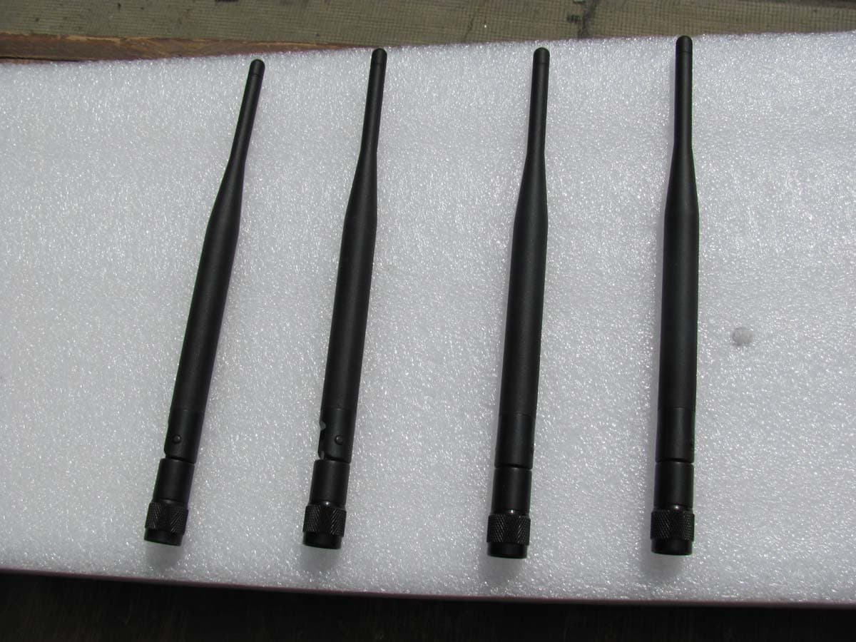
Click to zoom
Application Details
- Equipment Class
- DTS - Digital Transmission System
- Date of Grant
- Jun 18, 2012
- Application Purpose
- Original Equipment
- Date of Application
- Jun 18, 2012
- Equipment Note
- SC3500 MIMO Radio
- Frequency Range
- 5745.00000000 - 5830.00000000
- Company
- Silvus Technologies, Inc.
- Country
- United States
Documents & Files
Document Text
Text extracted from the exhibit documents filed with the FCC. Open a document above to read the original.
Users Manual
Document Number 10009C000 Version 1.2 Date 5/10/2012 Silvus Technologies, Inc. Confidential SC3500 Quick Start Guide CSMA Silvus Technologies, Inc. 10990 Wilshire Blvd, #440 Los Angeles, CA 90024 (310) 479-3333 www.silvustechnologies.com SC3500 Quick Start User Guide CSMA 5/10/2012 10009C000 Silvus Technologies Confidential Page i Notice Silvus Technologies reserves the right to make changes to its products or discontinue any of its products or offerings without notice. Silvus warrants the performance of its products to the specifications applicable at the time of sale in accordance with Silvus’ standard warranty. Revision History Copyright © 2012, Silvus Technologies Version Date Changes 1.0 November, 2011 Original 1.1 April 12, 2012 Added FCC Notice 1.2 May 10, 2012 Edited Text SC3500 Quick Start User Guide CSMA 5/10/2012 10009C000 Silvus Technologies Confidential Page ii Contents 1. Introduction.............................................................................................................................. 1 2. SC3500 Network...................................................................................................................... 1 3. Configuring the Radio.............................................................................................................. 1 4. Web Interface........................................................................................................................... 2 4.1 Basic ............................................................................................................................... 3 4.2 Advanced ........................................................................................................................ 4 5. Setting up an Iperf Test............................................................................................................ 5 5.1 Required Equipment ....................................................................................................... 5 5.2 Running Iperf Test.......................................................................................................... 5 6. Precautions and Recommendations ......................................................................................... 6 6.1 Saving the Radio Configuration ..................................................................................... 6 6.2 Network Tests................................................................................................................. 6 6.2.1 Ping .................................................................................................................... 6 6.2.2 Multicast............................................................................................................. 6 6.2.3 TCP dumps......................................................................................................... 6 7. FCC Notice .............................................................................................................................. 7 List of Figures Figure 1 Index.html page................................................................................................................ 1 Figure 2 Rebooting webpage .......................................................................................................... 2 Figure 3 Basic setting page............................................................................................................. 3 Figure 4 Advanced setting page...................................................................................................... 4 SC3500 Quick Start User Guide CSMA 5/10/2012 10009C000 Silvus Technologies Confidential Page 1 1. Introduction This quick start user guide contains all essential information for the user to configure the SC3500 radio and to also run an iperf network test. The configuration of the radio is done through a web interface. 2. SC3500 Network Each SC3500 radio has a fixed static IP address in the 172.20.0.0 network. The radio operates as a network switch; the user equipment does not need to be on the same subnet as the radio during operation. It is possible to setup a secondary IP address on the radio if the user finds this feature convenient. Setting up a secondary IP address is useful if the user wishes to access the radio’s web interface in his network. 3. Configuring the Radio Connect a laptop to the SC3500 using an Ethernet cable and turn on the SC3500. Users can type “ping IPaddress” in order to determine whether the SC3500 is up. A web configuration will be then available by typing the radio IP address in a web browser. Users will be redirected to an index.html webpage. (See Figure 1) Figure 1 Index.html page SC3500 Quick Start User Guide CSMA 5/10/2012 10009C000 Silvus Technologies Confidential Page 2 4. Web Interface “index.html” page will show up when users access SC3500 though a web browser. o This is a default web file that the users will see when first connecting to the radio web interface. Users can either select “Go to settings” or “Reboot”. If “Go to settings” is selected, the webpage will be directed to the setting interface. If “Reboot” is selected, the SC3500 will reboot (See Figure 2). Note the web interface will be unavailable during the rebooting process. Figure 2 Rebooting webpage The setting interface has two pages: Basic (See Figure 3), and Advanced (See Figure 4). SC3500 Quick Start User Guide CSMA 5/10/2012 10009C000 Silvus Technologies Confidential Page 3 4.1 Basic Figure 3 Basic setting page o This page is used to make basic configurations for the SC3500. o Frequency: This defines the frequency of the signal. There is a drop-down menu for frequency selection. o Bandwidth: This defines the bandwidth of the signal. o Save and Reboot: The new value for the frequency and bandwidth will be set as default values. Then reboot SC3500. o Transmit Power: This defines the power of the signal. o Apply: Apply the new power to the signal. The value…
Text truncated - open the document above for the full version.
Cover Letter(s)
Correspondence by Project Project Number: Correspondence NumberMemo N2S-SC3500-1 1) The sample FCC ID label does not include the required statement from section 15.19 of the FCC rules. Please provide a corrected FCC ID label. Response: Please see the revised exhibit that shows the new labels with the FCC statement from section 15.19 2) Please provide a new letter of appointment and Anti-drug abuse letter that is addressed to CETCB. Response: The letter has been uploaded. 3) Please provide data and calculations showing compliance to the MPE requirements. Response: The MPE Calculations have been uploaded 4) Please provide data showing compliance to the power variation requirements in section 15.31(e) of the FCC rules. Response: The 15.31 (e) Requirements have been uploaded. 5) Please provide information regarding the antennas used. Response: The antenna data sheet has been uploaded. 6) The photos of the device show a standard TNC connector being used, however this does not meet the requirements of section 15.203 which requires use of a unique connector. Please provide documentation showing compliance to the section 15.203 requirements. Response: The cover letter showing the requirements to this have been uploaded. 7) The operational description describes an additional four operational bandwidths that can be used, however only one was tested. Please provide data showing compliance to the other operational bandwidths. Response: The Operational Description has been revised and uploaded. 8) The user manual describes additional operational bandwidths and power levels that can be selected, however some of these were not tested or a above the allowed limits. Please provide a corrected user manual. Response: The Manual has been revised and uploaded.
Cover Letter(s)
L-COM, INC. 45 BEECHWOOD DRIVE NORTH ANDOVER, MA 01845 WWW.L-COM.COM E-MAIL: [email protected] PHONE: 1-800-343-1455 FAX: 1-978-689-9484 © L-com, Inc. All Rights Reserved. L-com Global Connectivity and the L-com logo are registered marks. HyperLink Wireless 2.4 GHz to 5.8 GHz 3 dBi TNC-Male Tri-Band Rubber Duck Antenna Applications and Features 2.4 GHz - 2.5 GHz Frequency Range: ◊ 802.11b, 802.11g, 802.11n Access Points and Routers ◊ 2.4 GHz ISM Applications ◊ WiFi Systems ◊ Bluetooth® Applications ◊ Public Wireless Hotspots ◊ Wireless Video Services 4.9 GHz - 5.3 GHz Frequency Range: ◊ 802.11a Access Points and Routers ◊ 5.3 GHz Band Applications ◊ Homeland Security ◊ Public Safety Services: Fire, Police, Security 5.7 GHz - 5.8 GHz Frequency Range: ◊ 5.8 GHz ISM Band Applications ◊ 5.8 GHz UNII Band Applications ◊ WiFi Systems ◊ 5.8 GHz Wireless Video Systems Superior performance ◊ Tri-Band operation ◊Better performance than most stock AP antennas ◊Flexible "Rubber ◊Duck" antenna ◊Tilt and swivel design ◊TNC-Male Connector ◊RoHS Compliant Model: HG2458RD-TM Description The HyperGain® Model HG2458RD is a high performance TriBand rubber-duck antenna designed to operate from 2.4 GHz to 2.5 GHz, 4.9 GHz to 5.3 GHz and 5.7 GHz to 5.8 GHz. The Multi-Band design of this antenna eliminates the need to purchase different antennas for each frequency. The TriBand design of this antenna helps reduce interference and noise since it will reject out-of-band signals between the three bands of this antenna. This omnidirectional "rubber-duck" antenna provides broad coverage and 3 dBi gain. Measuring 7.79" long, this flexible antenna features a tilt-and-swivel TNC-Male connector, allowing them to be used vertically, at a right angle, or any angle in-between. It is suitable as a replacement RF antenna for many radios that are equipped with TNC connectors. Specifications Electrical Specifications Frequency Ranges 2400-2500 MHz 4900-5350 MHz 5725-5850 MHz Gain 3 dBi Horizontal Beam Width 360° Impedance 50 Ohm Max. Power 50W VSWR < 2:1 L-COM, INC. 45 BEECHWOOD DRIVE NORTH ANDOVER, MA 01845 WWW.L-COM.COM E-MAIL: [email protected] PHONE: 1-800-343-1455 FAX: 1-978-689-9484 © L-com, Inc. All Rights Reserved. L-com Global Connectivity and the L-com logo are registered marks. Mechanical Specifications Weight .96 oz. (27 g) Length 7.79" (198 mm) Max. Diameter 0.51" (13.1 mm) Finish Matte Black Connector TNC-Male Operating Temperature -40° C to 60° C (-40° F to 140° F) Polarization Vertical Flame Rating UL 94HB RoHS Compliant Yes Dimensions RF Antenna Patterns Guaranteed Quality This product is backed by L-com's Limited Warranty
ID Label/Location Info
Labels for existing enclosure Label for future enclosure
ID Label/Location Info
Label Location
ID Label/Location Info
Label Location
RF Exposure Info
MPE Calculations For RF Exposure Requirements MIMO 4X4 OFDM Radio Model: SC3500 MIMO Radio Page 1 of 1 MAXIMUM PERMISSIBLE EXPOSURE FOR SUBPART C Calculations Power density at the specific separation: S = PG/(4R 2 π) S = (495.45 * 7.98) / (4 * 20 2 * π) S = 0.78656 mW/cm 2 (at 20 cm) Limit = 1 mW/cm 2 where S = Maximum power density (mW/cm 2 ) P = Power input to the antenna (mW) – 26.95 dBm G = Numeric power gain of the antenna R = distance to the center of the radiation of the antenna (20 cm = limit for MPE) The maximum permissible exposure (MPE) for the general population is 1 mW/cm 2 . The power density at 20 cm does not exceed the 1 mW/cm 2 . Therefore, the exposure condition is compliant with FCC rules. The numeric gain (G) of the antenna with a gain specified in dB is determined by: G = Log -1 (dB antenna gain/10) G = Log -1 (9.02 dBi/10) G = 7.98
Test Report
Report Number: B20330D1 FCC Part 15 Subpart B and FCC Section 15.247 Test Report MIMO 4X4 OFDM Radio Model: SC3500 MIMO Radio Brea Division 114 Olinda Drive Brea, CA 92823 (714) 579-0500 Agoura Division 2337 Troutdale Drive Agoura, CA 91301 (818) 597-0600 Silverado Division 19121 El Toro Road Silverado, CA 92676 (949) 589-0700 Lake Forest Division 20621 Pascal Way Lake Forest, CA 92630 (949) 587-0400 Page 1 of 24 FCC PART 15, SUBPART B and C TEST REPORT for MIMO 4X4 OFDM RADIO MODEL: SC3500 MIMO RADIO Prepared for SILVUS TECHNOLOGIES 10990 WILSHIRE BLVD., SUITE #440 LOS ANGELES, CALIFORNIA 90024 Prepared by:_____________________ KYLE FUJIMOTO Approved by:____________________ JAMES ROSS COMPATIBLE ELECTRONICS INC. 114 OLINDA DRIVE BREA, CALIFORNIA 92823 (714) 579-0500 DATE: APRIL 12, 2012 REPORT APPENDICES TOTAL BODY A B C D E PAGES 24 2 2 2 18 62 110 This report shall not be reproduced except in full, without the written approval of Compatible Electronics. Report Number: B20330D1 FCC Part 15 Subpart B and FCC Section 15.247 Test Report MIMO 4X4 OFDM Radio Model: SC3500 MIMO Radio Brea Division 114 Olinda Drive Brea, CA 92823 (714) 579-0500 Agoura Division 2337 Troutdale Drive Agoura, CA 91301 (818) 597-0600 Silverado Division 19121 El Toro Road Silverado, CA 92676 (949) 589-0700 Lake Forest Division 20621 Pascal Way Lake Forest, CA 92630 (949) 587-0400 Page 2 of 24 TABLE OF CONTENTS Section / Title PAGE GENERAL REPORT SUMMARY 4 SUMMARY OF TEST RESULTS 5 1. PURPOSE 6 2. ADMINISTRATIVE DATA 7 2.1 Location of Testing 7 2.2 Traceability Statement 7 2.3 Cognizant Personnel 7 2.4 Date Test Sample was Received 7 2.5 Disposition of the Test Sample 7 2.6 Abbreviations and Acronyms 7 3. APPLICABLE DOCUMENTS 8 4. DESCIRPTION OF TEST CONFIGURATION 9 4.1 Description of Test Configuration - Emissions 9 4.1.1 Cable Construction and Termination 10 5. LISTS OF EUT, ACCESSORIES AND TEST EQUIPMENT 11 5.1 EUT and Accessory List 11 6. TEST SITE DESCRIPTION 14 6.1 Test Facility Description 14 6.2 EUT Mounting, Bonding and Grounding 14 7. CHARACTERISTICS OF THE TRANSMITTER 15 7.1 Transmitter Power 15 7.2 Channel Number and Frequencies 15 7.3 Antenna Gain 15 8. TEST PROCEDURES 16 8.1 RF Emissions 16 8.1.1 Conducted Emissions Test 16 8.1.2 Radiated Emissions (Spurious and Harmonics) Test 17 8.1.3 RF Emissions Test Results 19 8.2 Emissions Bandwidth (EBW) 20 8.3 Peak Output Power 21 8.4 RF Antenna Conducted Test 21 8.5 RF Band Edges 22 8.6 Spectral Density Test 23 9. CONCLUSIONS 24 Report Number: B20330D1 FCC Part 15 Subpart B and FCC Section 15.247 Test Report MIMO 4X4 OFDM Radio Model: SC3500 MIMO Radio Brea Division 114 Olinda Drive Brea, CA 92823 (714) 579-0500 Agoura Division 2337 Troutdale Drive Agoura, CA 91301 (818) 597-0600 Silverado Division 19121 El Toro Road Silverado, CA 92676 (949) 589-0700 Lake Forest Division 20621 Pascal Way Lake Forest, CA 92630 (949) 587-0400 Page 3 of 24 LIST OF APPENDICES APPENDIX TITLE A Laboratory Accreditations and Recognitions B Modifications to the EUT C Additional Models Covered Under This Report D Diagrams, Charts, and Photos Test Setup Diagrams Radiated and Conducted Emissions Photos Antenna and Effective Gain Factors E Data Sheets LIST OF FIGURES FIGURE TITLE 1 Conducted Emissions Test Setup 2 Plot Map And Layout of Test Site Report Number: B20330D1 FCC Part 15 Subpart B and FCC Section 15.247 Test Report MIMO 4X4 OFDM Radio Model: SC3500 MIMO Radio Brea Division 114 Olinda Drive Brea, CA 92823 (714) 579-0500 Agoura Division 2337 Troutdale Drive Agoura, CA 91301 (818) 597-0600 Silverado Division 19121 El Toro Road Silverado, CA 92676 (949) 589-0700 Lake Forest Division 20621 Pascal Way Lake Forest, CA 92630 (949) 587-0400 Page 4 of 24 GENERAL REPORT SUMMARY This electromagnetic emission test report is generated by Compatible Electronics Inc., which is an independent testing and consulting firm. The test report is based on testing performed by Compatible Electronics personnel according to the measurement procedures described in the test specifications given below and in the "Test Procedures" section of this report. The measurement data and conclusions appearing herein relate only to the sample tested and this report may not be reproduced without the written permission of Compatible Electronics, unless done so in full. This report must not be used to claim product endorsement by NVLAP or any other agency of the U.S. Government. Device Tested: MIMO 4X4 OFDM Radio Model: SC3500 MIMO Radio S/N: N/A Product Description: See Expository Statement. Modifications: The EUT was not modified during the testing. Manufacturer: Silvus Technologies 10990 Wilshire Blvd., Suite #440 Los Angeles, California 90024 Test Dates: March 26, 27, 29, and 30, 2012 Test Specifications : EMI requirements CFR Title 47, Part 15, Subpart B; and Subpart C, sections 15.205, 15.209, and 15.247 Test Procedure: ANSI C63.4 Test Deviations: The test procedure was not deviated from during the testing. Report Number: B20330D1 FCC Part 15 Subpart B and FCC Section 15.247 Test Report MIMO 4X4 OFDM Radio Model: SC3500 MIMO Radio Brea Division 114 Olinda Drive Brea, CA 92823 (714) 579-0500 Agoura Division 2337 Troutdale Drive Agoura, CA 91301 (818) 597-0600 Silverado Division 19121 El Toro Road Silverado, CA 92676 (949) 589-0700 Lake Forest Division 20621 Pascal Way Lake Forest, CA 92630 (949) 587-0400 Page 5 of 24 SUMMARY OF TEST RESULTS TEST DESCRIPTION RESULTS 1 Conducted RF Emissions, 150 kHz – 30 MHz Complies with the Class B limits of CFR Title 47, Part 15 Subpart B; and the limits of CFR Title 47, Part 15, Subpart C, section 15.207 2 Spurious Radiated RF Emissions, 30 MHz – 1000 MHz Complies with the Class B limits of CFR Title 47, Part 15 Subpart B; and the limits of CFR Title 47, Part 15, Subpart C, section 15.209 3 Spurious Radiated RF Emissions, 10 kHz – 30 MHz and 1000 MHz – 40000 MHz Complies with the Class B limits of CFR Title 47, Part 15, Subpart B; and CFR Title 47, Part 15, Subpart C, sect…
Text truncated - open the document above for the full version.
Test Report
HOW THE EUT MEETS THE REQUIREMENTS OF 15.31 (e) FOR THE SILVUS TECHNOLOGIES MIMO 4X4 OFDM RADIO, MODEL: SC3500 MIMO RADIO The fundamental was maximized on the Lab B test site using a normal test setup with the AC Adapter connected directly to the AC public mains (115 Vac). Next, the AC Adapter for the EUT was then connected to the Staco Energy Products Variable Auto Transformer Model: 3PN1010. The Variable Auto Transformer allows the Vac input to be varied. The AC Adapter for the EUT was then connected to the Staco Energy Products Variable Auto Transformer Model: 3PN1010. The AC input was then dropped to 85% (97.75 Vac) and raised to 115% (132.25 Vac). The actual AC input was measured using a calibrated Wavetek Multimeter Model: DM25XT, Serial Number: 40209875, Calibration Due Date: May 27, 2012. The fundamental was then verified again to see that the amplitude did not change. Test Result: The EUT does NOT change amplitude at the fundamental when the AC input voltage is varied between 85% and 115% of the input nominal rated supply voltage.
Test Setup Photos
Report Number: B20330D1 FCC Part 15 Subpart B and FCC Section 15.247 Test Report MIMO 4X4 OFDM Radio Model: SC3500 MIMO Radio Brea Division 114 Olinda Drive Brea, CA 92823 (714) 579-0500 Agoura Division 2337 Troutdale Drive Agoura, CA 91301 (818) 597-0600 Silverado Division 19121 El Toro Road Silverado, CA 92676 (949) 589-0700 Lake Forest Division 20621 Pascal Way Lake Forest, CA 92630 (949) 587-0400 Page D13 FRONT VIEW SILVUS TECHNOLOGIES MIMO 4X4 OFDM RADIO MODEL: SC3500 MIMO RADIO FCC SUBPART B AND C – RADIATED EMISSIONS PHOTOGRAPH SHOWING THE EUT CONFIGURATION FOR MAXIMUM EMISSIONS Report Number: B20330D1 FCC Part 15 Subpart B and FCC Section 15.247 Test Report MIMO 4X4 OFDM Radio Model: SC3500 MIMO Radio Brea Division 114 Olinda Drive Brea, CA 92823 (714) 579-0500 Agoura Division 2337 Troutdale Drive Agoura, CA 91301 (818) 597-0600 Silverado Division 19121 El Toro Road Silverado, CA 92676 (949) 589-0700 Lake Forest Division 20621 Pascal Way Lake Forest, CA 92630 (949) 587-0400 Page D14 REAR VIEW SILVUS TECHNOLOGIES MIMO 4X4 OFDM RADIO MODEL: SC3500 MIMO RADIO FCC SUBPART B AND C – RADIATED EMISSIONS PHOTOGRAPH SHOWING THE EUT CONFIGURATION FOR MAXIMUM EMISSIONS Report Number: B20330D1 FCC Part 15 Subpart B and FCC Section 15.247 Test Report MIMO 4X4 OFDM Radio Model: SC3500 MIMO Radio Brea Division 114 Olinda Drive Brea, CA 92823 (714) 579-0500 Agoura Division 2337 Troutdale Drive Agoura, CA 91301 (818) 597-0600 Silverado Division 19121 El Toro Road Silverado, CA 92676 (949) 589-0700 Lake Forest Division 20621 Pascal Way Lake Forest, CA 92630 (949) 587-0400 Page D15 FRONT VIEW SILVUS TECHNOLOGIES MIMO 4X4 OFDM RADIO MODEL: SC3500 MIMO RADIO FCC SUBPART B AND C – RADIATED EMISSIONS PHOTOGRAPH SHOWING THE EUT CONFIGURATION FOR MAXIMUM EMISSIONS Report Number: B20330D1 FCC Part 15 Subpart B and FCC Section 15.247 Test Report MIMO 4X4 OFDM Radio Model: SC3500 MIMO Radio Brea Division 114 Olinda Drive Brea, CA 92823 (714) 579-0500 Agoura Division 2337 Troutdale Drive Agoura, CA 91301 (818) 597-0600 Silverado Division 19121 El Toro Road Silverado, CA 92676 (949) 589-0700 Lake Forest Division 20621 Pascal Way Lake Forest, CA 92630 (949) 587-0400 Page D16 REAR VIEW SILVUS TECHNOLOGIES MIMO 4X4 OFDM RADIO MODEL: SC3500 MIMO RADIO FCC SUBPART B AND C – RADIATED EMISSIONS PHOTOGRAPH SHOWING THE EUT CONFIGURATION FOR MAXIMUM EMISSIONS Report Number: B20330D1 FCC Part 15 Subpart B and FCC Section 15.247 Test Report MIMO 4X4 OFDM Radio Model: SC3500 MIMO Radio Brea Division 114 Olinda Drive Brea, CA 92823 (714) 579-0500 Agoura Division 2337 Troutdale Drive Agoura, CA 91301 (818) 597-0600 Silverado Division 19121 El Toro Road Silverado, CA 92676 (949) 589-0700 Lake Forest Division 20621 Pascal Way Lake Forest, CA 92630 (949) 587-0400 Page D17 FRONT VIEW SILVUS TECHNOLOGIES MIMO 4X4 OFDM RADIO MODEL: SC3500 MIMO RADIO FCC SUBPART B AND C – CONDUCTED EMISSIONS PHOTOGRAPH SHOWING THE EUT CONFIGURATION FOR MAXIMUM EMISSIONS Report Number: B20330D1 FCC Part 15 Subpart B and FCC Section 15.247 Test Report MIMO 4X4 OFDM Radio Model: SC3500 MIMO Radio Brea Division 114 Olinda Drive Brea, CA 92823 (714) 579-0500 Agoura Division 2337 Troutdale Drive Agoura, CA 91301 (818) 597-0600 Silverado Division 19121 El Toro Road Silverado, CA 92676 (949) 589-0700 Lake Forest Division 20621 Pascal Way Lake Forest, CA 92630 (949) 587-0400 Page D18 REAR VIEW SILVUS TECHNOLOGIES MIMO 4X4 OFDM RADIO MODEL: SC3500 MIMO RADIO FCC SUBPART B AND C – CONDUCTED EMISSIONS PHOTOGRAPH SHOWING THE EUT CONFIGURATION FOR MAXIMUM EMISSIONS
Contact Information
Applicant
Cyrus Naim(General Counsel)
Technical Contact
Compatible Electronics, Inc.Kyle Fujimoto
[email protected]714-579-0500
114 Olinda Drive · Brea, California · United States
Test Firm
Compatible Electronics, Inc.Michael Christensen
Technical Specifications
| # | Rule Parts | Frequency Range | Power Output |
|---|---|---|---|
| 2 | 15C | 5.75 GHz - 5.83 GHz | 493.62 mW |
Other Applications from Silvus Technologies, Inc.
N2S-SC42A-235-1W
Jul 28, 2026StreamCaster 2x2 MIMO Radio
Equipment Class
DTS - Digital Transmission SystemN2S-SC42X-235-1W
Jul 28, 2026StreamCaster 2x2 MIMO Radio
Equipment Class
DTS - Digital Transmission SystemN2S-SC42A-235-OEM
Nov 17, 2025StreamCaster Life
Equipment Class
DTS - Digital Transmission SystemN2S-SC424-235-OEM
Nov 17, 2025StreamCaster Life
Equipment Class
DTS - Digital Transmission SystemN2S-SL4210-245-OE
Jul 18, 2024StreamCaster Lite
Equipment Class
DTS - Digital Transmission System