Text extracted from the exhibit documents filed with the FCC. Open a document above to read the original.
® ® ® ® Battery Installation: 1.Open the Magic Tape at the back of Bobbie’s /Bobo’s Head and locate the battery compartment. (See Fig. 1) Product Content: ® Bobbie & Friends ® is a trademark of Fun Horizon Limited © 2010 Fun Horizon Limited. All Rights Reserved. Manufactured by Fun Horizon Limited. Customer Care: 1-877-387-0853 E-mail: [email protected] Website: www.bobbieandfriends.com Fun Horizon Limited, Rm 511-4, 5/F, Hunghom Commercial Centre, Tower A, 39 Ma Tau Wai Road, Hunghom, Kowloon, HK. Fun Horizon Inc 4195 Chino Hills Pkwy #515 Chino Hills, CA 91709 Hereby, Fun Horizon Limited, declares that this Bobbie & Friends ® Interactive Hand Puppet Set™ is in compliance with the essential requirements and other relevant provisions of Directive 1999/5/EC. The declaration of conformity may be consulted at http://www.bobbieandfriends.com/doc.pdf Item #.11008 01 Important Battery Information: In exceptional circumstances, batteries may leak uids that can cause a chemical burn injury or ruin your product. To avoid battery leakage: • Do not mix old and new batteries or batteries of dierent types: alkaline, standard (carbon-zinc) or rechargeable (nickel-cadmium). • Remove batteries during long periods of non-use. Always remove exhausted batteries safely. Do not dispose of product in a re. The battery inside may explode or leak. • Never short-circuit the battery terminals. • Use only batteries of the same or equivalent type, as recommended. • Remove rechargeable batteries from the product before charging. • If removeable, rechargeable batteries are used, they are only to be charged under adult supervision. Getting Started – Initial Setup 1. Turn the Power Switch located on the battery compartment of Bobo & Bobbie to “OFF” position (See Fig. 5) 2. Install new batteries in both Bobo the Hand Puppet and Bobbie the Receiver Doll according to the Battery Installation Instruction. 3. PAIRING SETUP – To pair up both devices’ connec- tion, turn the Power Switch located on the battery compartment of both devices to “ON” position. Pairing setup of the devices has to be initiated together and within 15 seconds. (See Fig. 6) 4. Pairing setup is done when you hear a “BLEEP” sound. Repeat the above steps if the devices fail to pair up. NOTE: This equipment has been tested and found to comply with the limits for a Class B digital device, pursuant to Part 15 of the FCC Rules. These limits are designed to provide reasonable protection against harmful interference in a residential installation. This equipment generates, uses and can radiate radio frequency energy and, if not installed and used in accordance with the instructions, may cause harmful interference to radio communications. However, there is no guarantee that interference will not occur in a particular installation. If this equipment does cause harmful interference to radio or television reception, which can be determined by turning the equipment o and on, the user is encouraged to try to correct the interference by one or more of the following measures: •Reorient or relocate the receiving antenna •Increase the separation between the equipment and receiver •Connect the equipment into an outlet on a circuit dierent from that to which the receiver is connected •Consult the dealer or an experienced radio/TV technician for help Caution: Changes or modications not expressly approved by the party responsible for compliance could void the user’s authority to operate the equipment. WARNING: • Never use the Bobbie & Friends ® Interactive Hand Puppet Set™ while driving or during any sporting activities as it may lead to accidents causing injuries. • Turn the Bobbie & Friends ® Interactive Hand Puppet Set™ o in an aircraft or any facility where posted notices restrict the use of radios or cellular telephones. Hospitals or health care facilities may be using equipment that is sensitive to RF energy. • Never Use the Bobbie & Friends ® Interactive Hand Puppet Set™ where personal medical devices such as pacemakers or hearing aids are in use. Turn the Interactive Hand Puppet Set™ o immediately if there is any reason to suspect that interference is taking place. • Never use the Bobbie & Friends ® Interactive Hand Puppet Set™ in front of a vehicle’s air-bag. If the air-bag deploys, it could propel the walkie-talkie and cause injuries. • Never use the Bobbie & Friends ® Interactive Hand Puppet Set™ or change the batteries in potentially explosive atmosphere as sparks in such areas could result in explosion. • Never use the Bobbie & Friends ® Interactive Hand Puppet Set™ in or near a mining facility, which uses remotely triggered explosives, or in areas labeled “Blasting Area”. Premature or accidental detonation may result. • Never attempt to modify or in any way increase the output power of the Bobbie & Friends ® Interactive Hand Puppet Set™ as it may cause a violation of the technical regulation of Part 15 of FCC Rules. • Avoid exposing the Bobbie & Friends ® Interactive Hand Puppet Set™ to water or extreme temperatures. Protect the environment by not disposing of this product with household waste(2002/96/EC). Check your local authority for recycling advice and facilities (Europe only). Interactive Hand Puppet Instruction Sheet 4 Jun 2012 ON OFF Your Bobbie & Friends ® Interactive Hand Puppet Set™ will achieve the maximum operating range when communicating in at open areas with no walls, trees or buildings to obstruct the signal. Under the ideal conditions, you may achieve range up to a 10-meter radius. The following conditions tend to reduce the range. • There are large obstructions such as walls, buildings, trees, vehicles, hills etc. between radios. • The batteries are running low. 2. Use a Phillips Screwdriver (not included) to unscrew and remove the battery compartment door. (See Fig. 2) 3. Install 3 X AAA (1.5V) alkaline batteries in the battery compartment of Bobbie/ Bobo. Be careful to align the positive (+) and negative (-) polarities with the…
Text truncated - open the document above for the full version.
Block diagram.bmp (1185x388x16M bmp) RF24DT-50DS 2.4GHz Digital RF Module Application Note * This specification are subject to be changed without notice. 10/1/2009 ~ ~ ~ ~ 3 33 3 ~ ~ ~ ~ 3. Block Diagram 4. Pins assignment
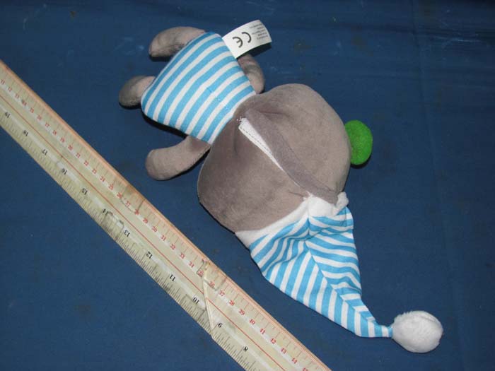
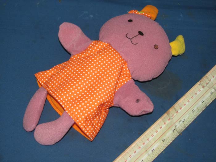
INTERTEK TESTING SERVICE Report No.: HK12051175-1 FCC ID: N39001 Equipment Photographs Model : 11008 (External)
Label Location
INTERTEK TESTING SERVICE Report No.: HK12051175-1 FCC ID: N39001 Equipment Photographs Model : 11008 (Internal) INTERTEK TESTING SERVICE Report No.: HK12051175-1 FCC ID: N39001 Equipment Photographs Model : 11008 (Internal) INTERTEK TESTING SERVICE Report No.: HK12051175-1 FCC ID: N39001 Equipment Photographs Model : 11008 (Internal) INTERTEK TESTING SERVICE Report No.: HK12051175-1 FCC ID: N39001 Equipment Photographs Model : 11008 (Internal) INTERTEK TESTING SERVICE Report No.: HK12051175-1 FCC ID: N39001 Equipment Photographs Model : 11008 (Internal) INTERTEK TESTING SERVICE Report No.: HK12051175-1 FCC ID: N39001 Equipment Photographs Model : 11008 (Internal) INTERTEK TESTING SERVICE Report No.: HK12051175-1 FCC ID: N39001 Equipment Photographs Model : 11008 (Internal) INTERTEK TESTING SERVICE Report No.: HK12051175-1 FCC ID: N39001 Equipment Photographs Model : 11008 (Internal)
Technical Description: The equipment under test (EUTs) is a BoBo the Hand Puppet for an interactive hand puppet doll which is operating at 2410 ~ 2470MHz with 1 MHz channel spacing. The EUT is powered by three AAA batteries. After powered ON the EUT and paired up the Slave unit (i.e. Bobbie the Receiver Doll), the user can speak to corresponding Slave unit by speaking to microphone for voice transmission. Frequency range: 2410 – 2470MHz Channel spacing: 1MHz Type of modulation: FSK The functions of main ICs are mentioned as below. 1) U1 acts as Microcontroller. 2) U2 acts as Flash Memory. For 2.4GHz module; 1) U1 acts as 2.4GHz RF transceiver. Publication Release Date: Sep.09. 2009 Document Version: V1.0 0 ELAN Microelectronics Corp. RF24DT-50DS 2.4GHz Digital RF Module Application Note Elan Microelectronics Corp. Office: NO. 12, Innovation 1st. RD., Science-Based Industrial Park, Hsinchu City, Taiwan, R.O.C. TEL: (03) 563-9977 FAX: (03) 563-0118 http://www.emc.com.tw RF24DT-50DS 2.4GHz Digital RF Module Application Note * This specification are subject to be changed without notice. 10/1/2009 ~ ~ ~ ~ 1 11 1 ~ ~ ~ ~ Contents 1.Description................................................................. 2 2.Feature..................................................................... 2 3.Block Diagram............................................................... 3 4.Pins assignment............................................................. 3 5.Function Description........................................................ 5 6.Application circuit......................................................... 6 7.Demo kit.................................................................... 7 8.PCB ......................................................................... 7 9.Technical................................................................... 8 10.BOM........................................................................ 9 11.Description of Operation Mode ............................................. 10 12.State Machine of Operation Mode ........................................... 12 13.System Flowchart........................................................... 13 14.Star Network............................................................... 19 15.Frame Structure............................................................ 22 16.Operation Timing Diagram .................................................. 23 17.SPI Interface Timing Diagram .............................................. 30 18.SPI Programmable Function Description ..................................... 32 19.Serial Register Format of Power ON Initialization ......................... 35 20.Appendix:.................................................................. 38 21.History:................................................................... 40 RF24DT-50DS 2.4GHz Digital RF Module Application Note * This specification are subject to be changed without notice. 10/1/2009 ~ ~ ~ ~ 2 22 2 ~ ~ ~ ~ 1. Description The EM198850H/AW is a CMOS integrated circuit that performs all functions from the antenna to the microcontroller for transmission and reception of a 2.4GHz digital data. This transceiver IC integrates most of the functions required for data transmission into a single integrated circuit. Additionally, the programmability implemented reduces significantly external components count, board space requirements and external adjustments. 2. Feature - Single-chip FSK transceiver - Auto ACK & Retransmit - Star-Network with 6 channels - Address and CRC computation - 1/1.6Mbps Data Rate - 1 ~ 64 bytes Payload Length - 64 bytes FIFO Size - 4-wire digital interface (SPI) - Boost data mode - Power supply range: 1.8 to 3.6V - Automatic bypass internal LDO in low supply voltage - Battery Low Supply Voltage Detector - Support 4 power modes: Active/Standby/Idle/Power Down - Operation range: -40 °C to +85 °C - Standard CMOS process - On-chip VCO, PLL and PLL Loop Filter - On chip channel filter Applications - Wireless mouse, keyboard, joystick - Keyless entry - Alarm and security system - Home automation - Surveillance - Automotive - Telemetry - Industrial sensors - Wireless data communication - Toys RF24DT-50DS 2.4GHz Digital RF Module Application Note * This specification are subject to be changed without notice. 10/1/2009 ~ ~ ~ ~ 3 33 3 ~ ~ ~ ~ 3. Block Diagram 4. Pins assignment RF24DT-50DS 2.4GHz Digital RF Module Application Note * This specification are subject to be changed without notice. 10/1/2009 ~ ~ ~ ~ 4 44 4 ~ ~ ~ ~ Pin Symbol Type Descriptions 19, 24. DVDD3/AVDD3 PWR Power supply voltage. Exposed Pad GND GND Ground connection. 1 IREF Analog Input Reference resistor pin, connect to an external resistor 2 VREG_OUT PWR On-chip voltage regulator output 3 AVDD_RF PWR RF power supply 4, 5. GND Ground connection. 6 RFIO RF 50Ω RF input/output 7 VMOD Analog I/O Connect to external capacitor for filtering 8 AVDD_PLL PWR PLL power supply 9 OSCI Analog I/O Crystal pin1 10 OSCO Analog I/O Crystal pin2 11 DVDD PWR Digital power supply 12 DR_IRQ Digital I/O a. Interrupt signal in buffer mode b. Data input/data output in direct mode 13 SPI_MISO Digital I/O a. Master input/slave output in SPI mode b. Data output in buffer mode 14 SPI_MOSI Digital I/O a. Master output/slave input in SPI mode b. Data input in buffer mode 15 SPI_CLK Digital I/O SPI input clock 16 CSn Digital I/O SPI selection/programming enable 17 IRQ_RSSI Digital I/O IRQ_RSSI output high - to indicate the MCU to read the RSSI, RSSI only valid during receiving signal - Let MCU know the channel is occupied 18 B_D Digital I/O Battery Low Power Detector 20 CE Digital I/O Chip enable, enable voltage regulator 21 DMC_P Analog I/O S Demodulator analog output, connect to an external AC coupling capacitor 22 DMC_N Analog I/O Demodulator analog output, connect to an external AC coupling capacitor 23 ADD_IF PWR RX IF power supply, voltage regulator output RF24DT-50DS 2.4GHz Digital RF Module …
Text truncated - open the document above for the full version.
1 2 3 4 ABCD 4 3 2 1 D CBA Title Number Revision Size A4 Date: 30-May-2012 Sheet of File: D:\NS project\Projects\NS0290\Schematic\NS0290 SCH V03 for FCC\Hand puppet SCH V03.DD Drawn By: MICROPHONE1 DVDD Play 4.5V 104 104 1k 3k 10u 5000p 32768Hz 30p 30p 3300pCAP 0.1u 3.3k ON/OFF 10uF 104 EXT12M 1 VDD 2 SPI_MISO 3 CE 4 SPI_CLK 5 SPI_MOSI 6 CSn 7 RSSI 8 DR_IRQ 9 GND 10 J?2.4 MODULE SPIRXCESPICLKSPITXSPICSRSSIIRQ DVDD DVSS IOA0 IOA1 IOA1 SPIRX CE SPICLK SPITX SPICS RSSI IRQ DVSS DVDD 104 VCC VCC AVDD AVDD C110uF 104 DVSS AVSS DVDD VPPEPM IOB14 IOB15 IOB14IOB15 DATACLKVPPVDD NormalNormalProgProg VPP DVSS VCOIN VCOIN DVSS_PLL DVSS_PLL 100K 104 DVSS DVDD RESET RESET DVSS 10uF 104 VSS_ADCV33_ADC 3k AVSS AVSS 18K 0.22uF OPI MICOUT AGC OPIMICOUT AGC AVSS 470K 4.7uF AVSS 104 AVSS DVSS DVDD 104 AVSS AVSS VCC Hand puppet TX part (OTP version) Hand puppet SCH V03A V03 1 / 2 Rx IOA6 TryMe Option Normal IOA7 Tx IOA6 IOA7 NormalProg EPM VDD_REG 15 V33_REG 16 VPP 17 VSS_REG 18 R32SEL 19 ACIN 65 VSS_DAC 64 VSS_PDAC 63 VSS_PDAC 62 EPM 20 VCOIN 21 IOA0 14 IOA1 13 IOA2 12 IOA3 11 IOA4 10 IOA5 9 IOA6 8 IOA7 7 VSS_IOA 6 VDD_IOA 5 IOA8 4 IOA9 3 IOA10 2 IOA11 1 IOA12 69 IOA13 68 IOA14 67 IOA15 66 AUDP 61 AUDP 60 VDD_DAC 59 VDD_PDAC 58 VDD_PDAC 57 AUDN 56 AUDN 55 VSS_PDAC 54 VSS_PDAC 53 RESETB 22 XTO 23 XTI 24 TEST 25 VSS_ADC 26 V33_ADC 27 VMIC 28 AGC 30 OPI 31 MICOUT 32 MICN 33 MICP 34 IOB0 35 VADREF 29 IOB1 36 IOB2 37 IOB3 38 IOB4 39 IOB5 40 IOB6 41 IOB7 42 VDD_IOB 43 VSS_IOB 44 IOB8 45 IOB9 46 IOB10 47 IOB11 48 IOB12 49 IOB13 50 IOB14 51 IOB15 52 U?GPCE2P064 VCC AVDD 12345 OTP connector DVSS Mic2Mic1 Mic2Mic1 DVDD Crystal and C1 must be connected during OTP program ming 10uF 104 VSS_ADC V33_ADC 100 12345 TryMe connector IOA6IOA4 IOA4 CS 1 SO 2 WP 3 GND 4 SI 5 SCLK 6 HOLD 7 VDD 8 32M SPI Flash M_CSSPIRX SPITXSPICLK 0.1uCAP DVDD DVSS SPEAKER AUDPAUDN GPCE2P064 AUDPAUDN RF circuit.bmp (1185x1347x16M bmp)
INTERTEK TESTING SERVICES Report No.: HK12051175-1 Sample No.: 1/2 Code: FCC15C_f / Effective Date: 24 Jun 2011 ( of ) Bandedge Plot – Pursuant to FCC Part 15 Section 15. 249 Requirement (Pass)
- The test report only allows to be revised within the retention period unless further standard or the requirement was noticed. - This report is for the exclusive use of Intertek's Client and is provided pursuant to the agreement between Intertek and its Client. Intertek's responsibility and liability are limited to the terms and conditions of the agreement. Intertek assumes no liability to any party, other than to the Client in accordance with the agreement, for any loss, expense or damage occasioned by the use of this report. Only the Client is authorized to permit copying or distribution of this report and then only in its entirety. Any use of the Intertek name or one of its marks for the sale or advertisement of the tested material, product or service must first be approved in writing by Intertek. The observations and test results in this report are relevant only to the sample tested. This report by itself does not imply that the material, product, or service is or has ever been under an Intertek certification program. Intertek Testing Services Hong Kong Ltd. 2/F., Garment Centre, 576 Castle Peak Road, Kowloon, Hong Kong. Tel: (852) 2173 8888 Fax: (852) 2785 5487 Website: www.hk.intertek-etlsemko.com TEST REPORT Report No.: HK12051175-1 Fun Horizon Ltd. Application For Certification (Original Grant) (FCC ID: N39001) Transceiver Prepared and Checked by: Approved by: Signed On File Wong Kwok Yeung, Kenneth Lead Engineer Chan Chi Hung, Terry Assistant Supervisor Date: June 07, 2012 INTERTEK TESTING SERVICES Report No.: HK12051175-1 FCC ID: N39001 i GENERAL INFORMATION Fun Horizon Ltd. BRAND NAME: Bobbie & Friends - Interactive Hand Puppet Set MODEL: 11008 FCC ID: N39001 Grantee: Fun Horizon Ltd. Grantee Address: Room 511-4, Hunghom Commercial Centre, Tower A, 39 Ma Tau Wai Road, Hunghom, Kowloon, Hong Kong. Contact Person: Eva Wong Tel: 852-2362 0281 Fax: 852-2764 0075 e-mail: N/A Manufacturer: N/A Manufacturer Address: N/A Brand Name: Bobbie & Friends - Interactive Hand Puppet Set Model: 11008 Type of EUT: Transceiver Description of EUT: 2.4G Interactive Hand Puppet Set Serial Number: N/A FCC ID: N39001 Date of Sample Submitted: May 18, 2012 Date of Test: May 31, 2012 Report No.: HK12051175-1 Report Date: June 07, 2012 Environmental Conditions: Temperature: +10 to 40°C Humidity: 10 to 90% INTERTEK TESTING SERVICES Report No.: HK12051175-1 FCC ID: N39001 ii SUMMARY OF TEST RESULT Fun Horizon Ltd. BRAND NAME: Bobbie & Friends - Interactive Hand Puppet Set MODEL: 11008 FCC ID: N39001 TEST SPECIFICATION REFERENCE RESULTS Maximum Peak Output Power 15.247(b), (c) / RSS-210 A8.4 N/A Hopping Channel Carrier Frequencies Separation 15.247(e) / RSS-210 A8.1 N/A 20dB Bandwidth of the Hopping Channel 15.247(a) / RSS-210 A8.1 N/A Number of Hopping Frequencies 15.247(e) / RSS-210 A8.1 N/A Average Time of Occupancy of Hopping Frequency 15.247(e) / RSS-210 A8.1 N/A Antenna Conducted Spurious Emissions 15.247(d) / RSS-210 A8.5 N/A Radiated Spurious Emissions 15.247(d) / RSS-210 A8.5 N/A RF Exposure Compliance 15.247(i) / RSS-Gen 5.6 N/A Transmitter Power Line Conducted Emissions 15.207 / RSS-Gen 7.2.4 N/A Transmitter Field Strength 15.227 / RSS-310 3.8 N/A Transmitter Field Strength 15.229 / RSS-210 A2.7 N/A Transmitter Field Strength, Bandwidth and Timing Requirement 15.231(a) / RSS-210 A1.1.1 N/A Transmitter Field Strength, Bandwidth and Timing Requirement 15.231(e) / RSS-210 A1.1.5 N/A Transmitter Field Strength and Bandwidth Requirement 15.239 / RSS-210 A2.8 N/A Transmitter Field Strength and Bandwidth Requirement 15.249 / RSS-210 A2.9 Pass Transmitter Field Strength and Bandwidth Requirement 15.235 / RSS-310 3.9 N/A Receiver / Digital Device Radiated Emissions 15.109 / RSS-210 2.5 N/A Digital Device Conducted Emissions 15.107 / ICES-003 N/A Note: 1. The EUT uses a permanently attached antenna which, in accordance to section 15.203, is considered sufficient to comply with the pervisions of this section. 2. Pursuant to FCC part 15 Section 15.215(c), the 20 dB bandwidth of the emission was contained within the frequency band designated (mentioned as above) which the EUT operated. The effects, if any, from frequency sweeping, frequency hopping, other modulation techniques and frequency stability over excepted variations in temperature and supply voltage were considered. INTERTEK TESTING SERVICES Report No.: HK12051175-1 FCC ID: N39001 iii Table of Contents 1.0 General Description....................................................................................... 1 1.1 Product Description ...................................................................................... 1 1.2 Related Submittal(s) Grants .......................................................................... 1 1.3 Test Methodology ......................................................................................... 1 1.4 Test Facility .................................................................................................. 1 2.0 System Test Configuration ............................................................................ 2 2.1 Justification................................................................................................... 2 2.2 EUT Exercising Software .............................................................................. 2 2.3 Special Accessories...................................................................................... 2 2.4 Equipment Modification................................................................................. 2 2.5 Measurement Uncertainty ............................................................................. 2 2.6 Support Equipment List and Description........................................................ 2 3.0 Emission Results ........................................................................................... 3 3.1 Field Strength Calculation ............................................................................. 3 3.2 Radiated Em…
Text truncated - open the document above for the full version.
INTERTEK TESTING SERVICE Report No: HK12051175-1 FCC ID: N39001 Configuration Photographs Worst-Case Radiated Emissions (Front View) Model : 11008 INTERTEK TESTING SERVICE Report No: HK12051175-1 FCC ID: N39001 Configuration Photographs Worst-Case Radiated Emissions (Back View) Model : 11008
2/F., Garment Centre, · Kowloon · Hong Kong
| # | Rule Parts | Frequency Range | Power Output |
|---|---|---|---|
| 1 | 15C | 2.41 GHz - 2.47 GHz | - |

2.4G Interactive Hand Puppet Set
Equipment Class
DXX - Part 15 Low Power Communication Device Transmitter