N3M001GPTVending Machine Interface Transceiver
GPT (USA) Inc.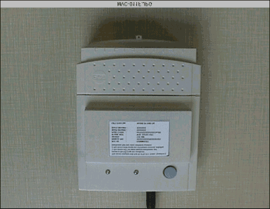
Click to zoom
Application Details
- Equipment Class
- TNB - Licensed Non-Broadcast Station Transmitter
- Date of Grant
- Aug 01, 1999
- Application Purpose
- Original Equipment
- Date of Application
- Mar 22, 1999
- Equipment Note
- Vending Machine Interface Transceiver
- Frequency Range
- 896.00000000 - 901.00000000
- Company
- GPT (USA) Inc.
- Country
- United States
Documents & Files
Document Text
Text extracted from the exhibit documents filed with the FCC. Open a document above to read the original.
Users Manual
Vending Interface Unit (VIU) Installation Guide 617/HH/30787/000 The information contained herein is the property of Marconi Communications and is supplied without liability for errors or omissions. No part may be reproduced or used except as authorised by contract or other written permission. The copyright and the foregoing restrictions on reproduction and use extend to all media in which the information may be embodied. © Marconi Communications 1999 All rights reserved GPT TELEMETRY SYSTEMS, MARCONI COMMUNICATIONS Edge Lane, Liverpool, United Kingdom L7 9NW Tel: International: +44 151 254 3000 Fax: International: +44 151 254 3029 VIUInstallation Guide iiCopyright - refer to title page.Issue: 3 Draft Installation GuideVIU Issue: 3 DraftCopyright - refer to title page.iii History This document consists of 23 pages, all at the same issue. Issue: 3 DraftFebruary 1999 Please address any comments to: GPT Telemetry Systems, MARCONI COMMUNICATIONS, Post Point 224, Faraday Building, 2nd Floor, Edge Lane, Liverpool. United Kingdom. L7 9NW. VIUInstallation Guide ivCopyright - refer to title page.Issue: 3 Draft Installation GuideVIU Issue: 3 DraftCopyright - refer to title page.v CONTENTS 1. VIU INSTALLATION IN ELECTRONIC AND ELECTRO-MECHANICAL VENDING MACHINES. ............................................................................................................1 1.1 U NPACK THE EQUIPMENT ..........................................................................................................1 1.2 V ERIFY THE E QUIPMENT S HIPPED .............................................................................................1 1.2.1 For electro-mechanical machines the required equipment is as follows : .......................1 1.2.2 For electronic machines the required equipment is as follows : ......................................3 1.3 T OOLS AND ACCESSORIES REQUIRED ........................................................................................4 1.4 T YPES OF V ENDER ....................................................................................................................5 1.5 I NITIAL P RECAUTIONS ...............................................................................................................5 1.6 A RRANGEMENT OF VIU AND MOUNTING BRACKET ...................................................................6 1.7 F ITTING THE VIU IN AN ELECTRO - MECHANICAL VENDER ..........................................................8 1.8 F ITTING THE VIU IN AN ELECTRONIC VENDER .........................................................................11 A PPENDIX A. P ARTS L ISTS ..........................................................................................................17 A PPENDIX B. T ROUBLE S HOOTING G UIDE .................................................................................25 VIUInstallation Guide viCopyright - refer to title page.Issue: 3 Draft Table of Figures F IGURE 1 S CHEMATIC WIRING DIAGRAM FOR VIU FITTED IN AN ELECTRO - MECHANICAL VENDER 14 F IGURE 2 S CHEMATIC WIRING DIAGRAM FOR VIU FITTED IN AN ELECTRONIC VENDER ................ 14 F IGURE 3 B LOCK DIAGRAM OF INSTALLATION PROCEDURE FOR V ENDER I NTERFACE U NIT .......... 15 Installation GuideVIU Issue: 3 DraftCopyright - refer to title page.1 1. VIU Installation in Electronic and Electro-mechanical vending machines. 1.1 Unpack the equipment • Remove all of the equipment from its packaging. • Check to ensure that there is no visible damage to the equipment or components. If damage is apparent, contact the freight company immediately to file a claim. • Check the equipment order, the delivery note and the actual equipment received, to ensure that the total order has been received. 1.2 Verify the Equipment Shipped 1.2.1 For electro-mechanical machines the required equipment is as follows : • the VIU, complete with mounting bracket Part No. 617/1/30787/200 • the Electro-mechanical Interface Unit. Part No. 617/1/23386/000 • the two Electro-mechanical interface cables. Refer to the Harness Cable Supplement sheet for Part No. references. VIUInstallation Guide 2Copyright - refer to title page.Issue: 3 • the Electro-mechanical Interface Unit to VIU communications cable. Part No. 617/1/23466/000 • 6 - No.8 x 9.5mm. Philips, pan head self-tapping screws. • 10 - Plastic cable ties. Installation GuideVIU Issue: 3 DraftCopyright - refer to title page.3 1.2.2 For electronic machines the required equipment is as follows : • the VIU, complete with mounting bracket. Part No. 617/1/30787/200 • the DEX (Direct exchange) cable. Part No. 617/1/30803/000 • the MDB (Multi-drop bus) cable Part No. 617/1/30802/000 • 6 - No.8 x 9.5mm. Philips, pan head self-tapping screws. • 10 - Plastic cable ties. VIUInstallation Guide 4Copyright - refer to title page.Issue: 3 1.3 Tools and accessories required • Cordless hand-drill. • No.6 Drill bits. • Philips-head screwdriver. • Side cutters. • Extra plastic cable ties. • Extra screws • Safety glasses Installation GuideVIU Issue: 3 DraftCopyright - refer to title page.5 1.4 Types of Vender Two types of vender are in use : • electro-mechanical . • electronic Identification of each type can be made by checking the equipment mounted inside the vender door. • Only the electronic vender is fitted with a Vending Machine Controller ( VMC ). This comprises the electronic circuitry enclosed within a metal box. For installations in an electro-mechanical vender, refer to para 1.7 page 8 . For installations in an electronic vender, refer to para 1.8 page 11. 1.5 Initial Precautions • Before carrying out any work inside the vender DISCONNECT THE ELECTRICAL SUPPLY . • First obtain any necessary permission from the vending machine supervisor or manager. • Unplug the electrical supply to the machine. • If the electrical supply is hard wired, schedule a qualified electrician to make the disconnection. • Unlock the vending machine and gain access to the rear of the door to enable installat…
Text truncated - open the document above for the full version.
Block Diagram
GPT Telemetry Systems, GPT Ltd. United Kingdom, Edge Lane, Liverpool, L7 9NW RFDB Block Diagram SIZE FSCM NO DWG NO REV B A SCALE none SHEET 1 OF 1 T/R Switch FX909 Mobitex Processor 938 MHz Bandpass LNA 902 MHz Lowpass Power Amplifier Lowpass Matching PreDriver Power Divider 938 MHz Bandpass RF2401 38.85 MHz Crystal Bandpass 898.5 MHz VCO SA607 450 kHz Ceramic Bandpass 450 kHz Ceramic Bandpass 450 kHz Ceramic Discriminator Data Lowpass 38.40 MHz Bandpass Frequency Trippler Synthesizer Power Divider 12.80 MHz TCXO Data Lowpass Microcontroller Control and Data
Cover Letter(s)
GPT (USA) Inc 2975 Northwoods Parkway, Norcross GA 30071 GPT (USA) Inc is a Marconi Communications Company F C C A U T H O R I Z A T I O N Date: 18 th March 1999 Time: 9.00am To: FCC Authorization & Evaluation Division 7435 Oakland Mills Road Columbia, MD 21045-0429 From: Ms Pat Hoffman Phone : 630 238 3995 Company Secretary Fax: 630 238 3998 Applicant : GPT (USA) Inc. E-Mail: ______________________________________________________________ __________ Dear Ladies and/or Gentlemen: I appoint Kenneth L. Boston and James Blaha at L.S. Compliance, Inc., to act as an agent in the preparation under Part 15 of the rules and regulations of the Federal Communications Commission. I certify that the exhibitions properly describe the device being submitted under this application and will implement any changes described in the test report. The labels described will be affixed to each item. The following statement is required by the Federal Communications Commission: By checking Yes , the applicant certifies that, in the case of an individual applicant, he or she is not subject to a denial of federal benefits, that included FCC benefits, pursuant to section 5301 of the Anti- Drug Abuse Act of 1988, 21 U.S.C 853(a), or, in the case of a non-individual applicant (e.g. corporation, partnership, or other unincorporated association), no party to the application is subject to a denial of federal benefits, that includes FCC benefits, pursuant to that section. ___X___YES _______NO Dated this 18 th day of March, 1999 GPT (USA) Inc 2975 Northwoods Parkway, Norcross GA 30071 GPT (USA) Inc is a Marconi Communications Company By: P Hoffman Title: Company Secretary, GPT (USA) Inc. Phone: 630 238 3995
External Photos
GPT Modem - Front of Case with FCC Label
External Photos
GPT Modem - Back of Modem Case
External Photos
GPT Modem - Open for Inspection
ID Label/Location Info
SAMPLE FCC LABEL Note exact layout / orientation / sizing to be determined. Label to be mounted on the battery bulge on the front of the VIU. This device complies with Part 90 of the FCC Rules. Operation is subject to the following two conditions: 1) this device may not cause harmful interference, and 2) this device must accept any interference received, including interference that may cause undesired operation. FCC ID : N3M001GPT SERIAL NO. : XXXXXXXXXXXXXXXX MODEL : VIU 200 WARR. REF :WSL XX/XX GPT PART CODE :617/1/XXXXX/XXX Iss 0X MAIN BOARD :XXXXXX DAUG BOARD :XXXXXX GPT (USA) Inc.MADE IN THE UK
ID Label/Location Info
GPT Modem - FCC Label Close Up
Internal Photos
GPT Modem - Case with battery, RF PCB and VIU PCB
Internal Photos
GPT Modem - RF PCB and VIU PCB
Internal Photos
GPT Modem - Close Up of RF PCB Shielded Side
Internal Photos
GPT Modem - Close Up of RF PCB Component Side
Internal Photos
GPT Modem - Close Up of VIU PCB Component Side
Internal Photos
GPT Modem - Close Up of VIU PCB Foil Side
Operational Description
GPT (USA) Inc 2975 Northwoods Parkway, Norcross GA 30071 GPT (USA) Inc is a Marconi Communications Company 1. Overall System Objective The system aims to improve the management of full service vending machines. This translates to reducing the number of visits to a particular machine, while reducing the time that a given product is sold-out, i.e. not available for sale. This increase in operating efficiency will produce increased sales, while allowing depot staff to support more machines, without increasing their daily workload. 2. System Architecture The system consists of 3 primary elements; these are the population of vending machines to be monitored, a Vending Management System, and a Graphical user interface terminal, based at the bottler's depot. 3. System Operation Each vending machine to be monitored is fitted with a telemetry device called a VIU, Vending Interface Unit. It is this unit for which FCC approval is sought. The VIU consist of two printed circuit boards, a motherboard and a communications interface board. The two boards are fitted within a single case, to become an operational unit, VIU. The VIU is fitted within the vending machine, usually behind the Perspex front screen, on a mounting plate. If the machine is electronic, the DEX/UCS port is used to obtain information on the machine status. If the machine is electromechanical, a separate electromechanical interface is fitted, which taps into the machine harness, and allows the VIU to monitor the operation of the machine. The VIU obtains its power either from the MDB port in the machine or via the electromechanical interface. An UL approved power pack can also be used to power the VIU. The VIU reports the machine status to the Vending Management system, via the integrated communications interface board. This board is in fact an integrated Mobitex data packet radio modem, and has been designed for operation with the BellSouth - RAM Mobitex network. An antenna is GPT (USA) Inc 2975 Northwoods Parkway, Norcross GA 30071 GPT (USA) Inc is a Marconi Communications Company Page 2 fitted into the top of the VIU case normally, i.e. within the machine. In areas of poor reception an external antenna mounted to the top of the vending machine may be required. The RAM network carries the radio traffic generated via the VIU, to the Vending Management System, which will be located in Atlanta, GA. The radio traffic is converted to an X25 data stream by the RAM network, which is then processed by the Vending Management System. Data from all the vending machines is stored at the Vending Management System, and is accessible to the bottlers. It is expected that with the exception of alarm calls, all transmissions from the VIU's will be at night, allowing the status of all the machines to be updated, before the bottlers start work the following morning. At the bottler's depot, the GUI will be used to contact the Vending Management System using the normal phone network and a modem, and will download the appropriate information. The GUI will then produce a set of reports, allowing the bottler to determine which vending machines need to be visited. The GUI and the Vending Management System are software programs running on standard computer platforms, and do not require FCC approval. 4. Early Field Trials The system concept has already been proven using approved RAM Mobitex radio's, external to the VIU case. However, the VIU has now been redesigned to operate with an integrated ram radio, and this design is expected to go in to full production shortly.
Operational Description
L.S. RESEARCH Inc. HIGH TECHNOLOGY ELECTRONIC CONSULTANTS File:50695CONFIDENTIALPage 1 of 1 July 29, 1999 References: EAS 93627, # 8364 Antenna used for GPT vending machine application is: Andrew Corporation Model 580003A
Test Report
L. S. COMPLIANCE, Inc. FCC ID: N3M001GPT LSC-GPT 0 COMPLIANCE TESTING OF GPT 900 MHZ TRANSMITTER GPT MODEM TESTS PERFORMED; 18 MARCH, 15 APRIL OF 1999 - R ADIATED E MISSIONS T EST R EPORT - 19 April, 1999 All results of this report relate only to the items that were tested. This report is not to be reproduced, except in full, without written approval of L.S.Compliance, Inc. L. S. COMPLIANCE, Inc. FCC ID: N3M001GPT LSC-GPT 1 L. S. COMPLIANCE, Inc. FCC ID: N3M001GPT LSC-GPT 2 Table of Contents: Section DescriptionPage # Description of Measurement Facility2 1.1Cover Page2 1.2Signature Page3 1.3Summary of Test Report4 1.4Introduction5 1.5Purpose5 1.6Radiated Emission Test Setup5 1.7Radiated Emission Test Procedure6 1.8Radiated Emission Test Equipment Utilized7 1.9Conducted Emission Measurements7 1.11Photos taken during testing8 1.12Summary of Results and Conclusions10 1.13Test Equipment List11 Appendic es ASample Calculations:12 i.Calculation of Radiated Emissions Limits13 BData Charts14 CGraphs16 L. S. COMPLIANCE, Inc. FCC ID: N3M001GPT LSC-GPT 3 D ESCRIPTION OF M EASUREMENT F ACILITIES Site on File with the FCC ID Number: 31040/SIT 1300F2 “ The site referenced above has been found to comply with the test site criteria found in ANSI C63.4-1992 and 47CFR Section 2.948.” L. S. COMPLIANCE, Inc. FCC ID: N3M001GPT LSC-GPT 4 SIGNATURE PAGE Testing by:19 April 1999 Prepared By: Approved By: 19 April 1999 Kenneth L. Boston, EMC Lab ManagerDate PE #31926 Registered Professional Engineer (State of Wisconsin) L. S. COMPLIANCE, Inc. FCC ID: N3M001GPT LSC-GPT 5 1.3 S UMMARY OF T EST R EPORT MANUFACTURER:GPT MODEL:RFDB Modem SERIAL:preproduction DESCRIPTION:900 MHz SMR modem, SMR service (Mobitex) FREQUENCY RANGE:896-901; 935-940 MHz The Modem was found to "meet” the radiated emission specification of 47 CFR, 90.210d, and the Mobitex specification. L. S. COMPLIANCE, Inc. FCC ID: N3M001GPT LSC-GPT 6 1.4 I NTRODUCTION On March 18, and April 15 of 1999, a series of Radiated Emissions tests were performed on a sample model of the GPT 2 watt 900 MHz modem. These tests were performed using the test procedures outlined in ANSI C63.4-1992 for intentional radiators, and in accordance with the limits set forth in FCC Part 90.210d and the Bell South MIS, 1998. These tests were performed by Thomas T Lee and Kenneth L. Boston, PE, of L. S. Compliance, Inc. and witnessed by John Lofgren of L. S. Research. 1.5 P URPOSE The above mentioned tests were performed in order to determine the compliance of the GPT product with limits contained in various provisions of Title 47 CFR, FCC Part 90.210. All radiated emissions tests were performed to measure the emissions in the frequency bands described by the above sections, and to determine whether said emissions are below the limits established by the above sections. These tests were performed in accordance with the procedure described in the American National Standard for methods of measurement of Radio- Noise Emissions from Low-Voltage Electrical and Electronic Equipment in the Range of 9 kHz to 40 GHz (ANSI C63.4-1992). Another document used as reference for the EMI receiver specification was the International Special Committee on Radio Interference (CISPR) number 16-1 (1993). Reference was also made to sections of the Bell South MIS for 1998. 1.6 R ADIATED E MISSIONS T EST S ETUP The test sample was operated within the 3 meter Semi-Anechoic, FCC listed chamber located at L.S. Compliance in Cedarburg, WI. The sample was placed on an 80cm high wooden table, which was centered on the flush-mounted 2m diameter metal turntable. The test sample was operated on a regulated 12 volt DC power source. The test sample was configured to run in a continuous transmit mode during the measurements, while the output port was terminated with a non-radiating 50 ohm dummy load. One test sample set to operate on two of the standard channels was tested as an intentional radiator, in order to determine compliance at a frequency of 896 and 900 MHz, Please refer to Section 1.11 for pictures of the test setup. L. S. COMPLIANCE, Inc. FCC ID: N3M001GPT LSC-GPT 7 1.7 R ADIATED E MISSION T EST P ROCEDURE The fundamental and spurious (harmonic) emissions of the transmitter were tested for compliance to Title 47 CFR, FCC Part 90. For the calculations used to determine the limits applicable for the test sample, refer to Appendix A. These limits are expressed in decibels (dB) above 1 microvolt per meter The fundamental and spurious (harmonic) emissions of the transmitter were tested for compliance to Title 47 CFR, FCC Part 90.210 limits for transmitters in the SMR services. For the calculations used to determine the limits applicable for the test sample, refer to Appendix A. These limits are expressed in decibels below carrier level. (-dBc) The samples were tested from the lowest frequency generated by the transmitter (without going below 9 kHz) to the 10th harmonic of the fundamental frequency generated by the device. The samples were placed on a nonconductive (wooden) pedestal in the 3 Meter chamber and the antenna mast was placed such that the antenna was 3m from the test object. A biconical antenna was used to measure emissions from 30 to 200 MHz, a log periodic was used to measure emissions from 200 to 1000 MHz, and a double ridged waveguide horn was used to measure emissions above 1 GHz. The test object was set to operate in continuous transmit, and the resultant signals were maximized by rotating the turntable 360 degrees, and by raising and lowering the antenna between 1 and 4 meters. The test object was also given several different orientations to determine the maximum signal levels, using both horizontal and vertical antenna polarities. Signal levels found were compared to an equivalent signal level of a generated carrier radiated from a dipole located at the EUT position. The required level for the transmitter harmonics and spurious signals where measured by means of a radiated measurement made in …
Text truncated - open the document above for the full version.
Test Report
.......... . . . . . . . . . . LS Research Inc. GPT Mobitex MODEM Part 90 Type Acceptance, Conducted Measurements prepared for GPT L.S. Research Inc. W66 N220 Commerce Court Cedarburg, WI 53012 Phone 414.375.4400 Fax 414.375.4248 Revision 1.0 L.S. RESEARCH Inc. 2 HIGH TECHNOLOGY ELECTRONIC CONSULTANTS Confidential WE HAVE DESIGNS ON THE FUTURE W66 N220 Commerce Court, Cedarburg, Wisconsin 53012 • 414-375-4400 • FAX 414-375-4248 Email: [email protected] www.lsr.com Table of Contents I.PROJECT INFORMATION ............................................................................................................................. 3 II. FCC CONDUCTED TESTS.............................................................................................................................. 5 A.P ART 90 S UBPART I ........................................................................................................................................... 5 1.90.207 (a) (1) Types of Emissions (Device Classification) .......................................................................... 5 2.90.209 (a) (5) Bandwidth Limitations (Device Classification, Test Condition). ......................................... 5 3.Part 2.985 Output Power, Part 2.991 Spurious Emissions at Antenna terminals and Part 2.989 Occupied bandwidth using 90.210 (j), and 90.211 Emission Mask for F1D Transmitter..................................................... 5 4.Part 2.995 and 90.213 (a) Frequency Stability........................................................................................... 15 III.EQUIPMENT LIST ...................................................................................................................................... 17 IV.EQUIPMENT UNCERTAINTIES .............................................................................................................. 17 V.UNCERTAINTY ANALYSIS .......................................................................................................................... 18 L.S. RESEARCH Inc. 3 HIGH TECHNOLOGY ELECTRONIC CONSULTANTS Confidential WE HAVE DESIGNS ON THE FUTURE W66 N220 Commerce Court, Cedarburg, Wisconsin 53012 • 414-375-4400 • FAX 414-375-4248 Email: [email protected] www.lsr.com Mobitex MODEM I. Project Information Project: Mobitex MODEM GPT Contact: Company: GPT Telemetry Systems Full Name: Martin Heffernan Job Title: Operations Manager Bus: 011 44 151 254 5151 Bus Fax: 011 44 151 254 3865 E-mail: [email protected] L.S. RESEARCH Inc. 4 HIGH TECHNOLOGY ELECTRONIC CONSULTANTS Confidential WE HAVE DESIGNS ON THE FUTURE W66 N220 Commerce Court, Cedarburg, Wisconsin 53012 • 414-375-4400 • FAX 414-375-4248 Email: [email protected] www.lsr.com LS Research Contact: Bill Steinike, Operations Manager John Lofgren, Test Engineer Brian Petted, Vice President of Engineering Voice: 414-375-4400 Fax:414-375-4248 Email: [email protected] Proposal Date: Revision: Proposal #: Proposal File: Job Number: Signatures: Technical Approval L.S. RESEARCH Inc. 5 HIGH TECHNOLOGY ELECTRONIC CONSULTANTS Confidential WE HAVE DESIGNS ON THE FUTURE W66 N220 Commerce Court, Cedarburg, Wisconsin 53012 • 414-375-4400 • FAX 414-375-4248 Email: [email protected] www.lsr.com II. FCC Conducted Tests A. Part 90 Subpart I 1. 90.207 (a) (1) Types of Emissions (Device Classification) Classified as an F1D emitter (Frequency Modulation, Digital Modulation, telemetry data). Power levels: 2W. 2. 90.209 (a) (5) Bandwidth Limitations (Device Classification, Test Condition). 12.5 kHz Nominal Channel Bandwidth 3. Part 2.985 Output Power, Part 2.991 Spurious Emissions at Antenna terminals and Part 2.989 Occupied bandwidth using 90.210 (j), and 90.211 Emission Mask for F1D Transmitter. a) Test Requirement: ( 1) On any frequency from the center of the authorized bandwidth by a displacement frequency of more than 2.5 kHz, but no more than 6.25 kHz: At least 53log(f d /2.5) dB. (2) On any frequency removed from the center of the authorized bandwidth by a displacement frequency (f d in kHz) of more than 6.25 kHz but no more than 9.5 kHz: At least 103log(f d /3.9) dB. (3) On any frequency removed from the center of the authorized band by a displacement frequency (f d in kHz) of more than 9.5 kHz : At least 157log(f d /5.3), or 50+10log(P), dB or 70 dB, whichever is the lesser attenuation. The test condition is presented in Tabular form below. The definition of the spectrum mask as indicated on the spectrum analyzer is also presented. L.S. RESEARCH Inc. 6 HIGH TECHNOLOGY ELECTRONIC CONSULTANTS Confidential WE HAVE DESIGNS ON THE FUTURE W66 N220 Commerce Court, Cedarburg, Wisconsin 53012 • 414-375-4400 • FAX 414-375-4248 Email: [email protected] www.lsr.com 90.210 (j)Absolute Frequency Offset Range (kHz): |f m | Attenuation relative to Carrier power P. (1)2.5 to 6.25 53log(f d /2.5) dB (2)6.25 to 9.5 103log(f d/ /3.9) dB (3)> 9.5 Min (157log(fd/5.3, 50 + 10 log 10 (P) dB ,70 dB) L.S. RESEARCH Inc. 7 HIGH TECHNOLOGY ELECTRONIC CONSULTANTS Confidential WE HAVE DESIGNS ON THE FUTURE W66 N220 Commerce Court, Cedarburg, Wisconsin 53012 • 414-375-4400 • FAX 414-375-4248 Email: [email protected] www.lsr.com b) Test Configuration PC HP8596E Equipment Under Test (Transmitter) Equipment Under Test Configuration Data Capture RF Output 20 dB Atten c) Test Conditions: Stimulus Set transmitter for single frequency, +30 dBm output power, pseudorandom test data modulation. Measure Spectrum Mask (j). d) Equipment Under Test Conditions, Instrument Conditions and Indicated Numerical Data for Part 2.985 Output Power. Presented below is a table that summarizes the equipment under test conditions, instrument conditions and numerical data. Numerical Data for the Transmitter Power under each of the test conditions is indicated in the Table. The source of the numerical data is presented in sub-sections(e),and (f), Test Indications. Demonstration of compliance is presented in sub- sections (e) and (f). L.S. RESEARCH Inc. 8 HIGH TECHNOLOGY ELECTRONIC CONSULTAN…
Text truncated - open the document above for the full version.
Contact Information
Applicant
Patricia Hoffman(Secretary)
630-238-3995
Technical Contact
GPTChristopher Cox
[email protected]011-44-151-254-3001
Edge Lane ( PP224 ) · Liverpool · United Kingdom
Non-Technical Contact
L. S. Compliance, Inc.Jim Blaha
[email protected]414-375-4400
Test Firm
L. S. Compliance, Inc.James Blaha
262-375-4400Fax: 262-375-4248
Technical Specifications
| # | Rule Parts | Frequency Range | Power Output | Emission | Tolerance |
|---|---|---|---|---|---|
| 1 | 90 | 896 MHz - 901 MHz | 2 W | 12K8F1D | 1.4500000000 ppm |