N3USHT9C4USRemote Control Transmitter
SVS Nachrichtentechnik GmbH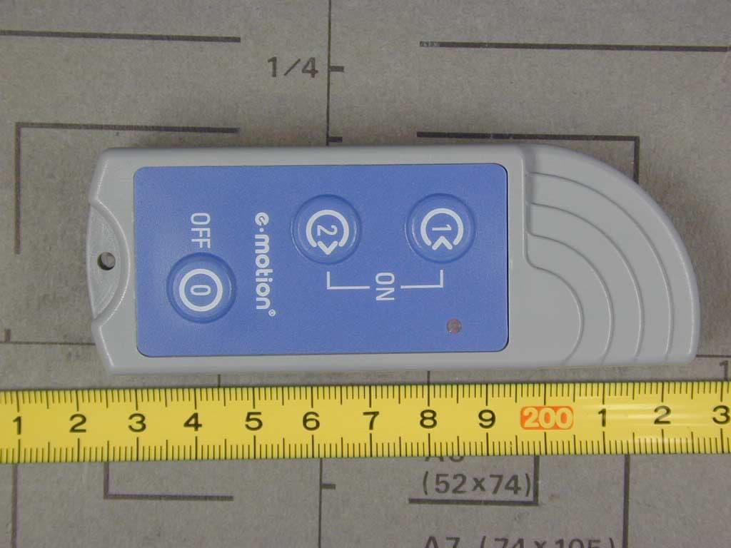
Click to zoom
Application Details
- Equipment Class
- DXX - Part 15 Low Power Communication Device Transmitter
- Date of Grant
- Sep 11, 2002
- Application Purpose
- Original Equipment
- Date of Application
- Sep 11, 2002
- Equipment Note
- Remote Control Transmitter
- Frequency Range
- 910.00000000 - 910.00000000
- Company
- SVS Nachrichtentechnik GmbH
- Country
- Germany
Documents & Files
Document Text
Text extracted from the exhibit documents filed with the FCC. Open a document above to read the original.
Users Manual
emotionü R OperatingInstructionsforUSAandCanada R RemoteControl 1 2 3 4 2 3 1 Operatinginstructions Threefunctionscanbecontrolledwiththee-motionremotecontrol: 1=Switchonbothe-motionwheelsinsupportlevel1(LED[2]lightsupbriefly). 3=Switchonbothe-motionwheelsinsupportlevel2(LED[2]lightsupbriefly). 4=Switchoffbothe-motionwheels(LED[2]lightsupbriefly). Note:Allremotecontrolsaredeliveredinausablestatecompletewithbattery.IftheLED[2]flashesthenthebatterycapacity isalmostexhausted. Takecarenottodroptheremotecontrolandtrytoavoidallkindsofimpact. Undernocircumstancesshouldyoucarrytheremotecontrolintrouserpocketsaspotentialinadvertentswitchingcouldresult. Insteadusethecordprovided(thelengthcanbeadjustedasrequired)orusetheholderthatcanbeattachedtothe wheelchair. Onlyoperatetheremotecontrolwhenthewheelsareatastandstill,neverduringajourney. Changingthebattery(seediagramonthejacket) Theusefullifeofthebatteryisdependentontheamountofusethattheremotecontrolgets. Iftherangeismarkedlyreducedornofunctionsworkanymorethenthebatterymustbereplaced. Pleaseobservethecorrectpolaritywhenfittingthenewbattery! Afterchangingthebatterytightenthescrewsbyhand,butdonotmakethentootight.Ifthescrewsaretightened toomuchthetwosectionsofhousingcanbepressedtogethertoomuch.Thentheunitwillnolongerfitintothe holderonthewheelchair. Useonly12Valkalinebatteries. Theusedbatteryshouldnotbedisposedofinthehouseholdrubbish.Itshouldbetakentoapublicspent batterycollectionpointoroneinashop. ü ü ü ü ü ü ü 1 Systemrange Thee-motionremotecontrolisdesignedtooperatemosteffectivelyatrangesupto10metres.Wallsandevensteel constructionscanbepenetratedbythesystem.Themaximumrangeisonlyattained,however,ifthereisalineof sighttothereceiverandifthereisnohighfrequencyinterference. Potentialcausesofreducedrange: -Buildingsofallkindsandvegetationinfluencetherange. -Thedistanceoftheaerialfromthebodyandtootherconductingsurfacesorobjects(includingtheground)strongly influencestheradiationcharacteristicsandthereforetheeffectiverange. -The“backgroundnoise”innon-ruralareascanbequitehigh,whichreducesthesignaltonoiseratioandsoalsothe range.Itcanalsonotberuledoutthatdeviceswithasimilarworkingfrequencyareoperatinginthe neighbourhoodandsoappeartomakethereceiverlesssensitive. -Ifthereceiverisnearbadlyscreeneddevicesthatproduceradiation(e.g.PC's),markedreductionsinrangeoran apparentcompletefailureofthereceivertoworkmayoccur. Properusage Thee-motionremotecontroltransmitsanindividuallycodedsignalbyradiowavestotheassociatedreceiverinthee-motion wheel.Thefunctionthatthentakesplacedependsonthereceiveranditswiring. Pleaserememberthatwirelesscommunicationisalwayspotentiallysubjecttointerference! Thee-motionremotecontrolmustnotbemodifiedorrebuiltanditcanbeusedwithoutbeingregisteredandwithoutanyfees beingpaid. Thee-motionremotecontrolisapprovedforuseintheUSAandCanada. 2 Generalinformation alber Disposal alberalber Pleasereadtheoperatinginstructionscarefully.isnotliableforanyconsequentialdamagesthatresultfromtheuseofthe device,norformaterialdamageorpersonalinjurycausedbyimproperhandlingorthroughignoringtheinstructions.Insuch casesallclaimsundertheguaranteearealsovoid. Thetechnicalconstructionofthee-motionremotecontrolmeetsnationalandinternationalrequirementsforelectromagnetic tolerances. Youre-motionremotecontrolisaproductwithalongworkinglife.Attheendofitsusefullifetheremotecontrolmaybe returnedtoordealerswhowillensurethatitisproperlydisposedofinanenvironment-friendlymanner. Theusedbatteryshouldnotbedisposedofinthehouseholdrubbish.Itsholdbetakentoapublicspentbatterycollectionpoint oroneinashop. Technicaldata Workingfrequency:910Mhz Powersupply:12ValkalinebatteryA23 Currentconsumption:typ.15mA Workingtemperature:-10°Cto+65°C(storage-40°C/+85°C) Housingdimensions:100mmx37mmx19mm Caution:Anymodificationtotheequipmentnotexpressivelyauthorizedbythepartyresponsibleforcompliancecould voidtheusersauthoritytooperatetheequipment 3 Informationforspecialistdealers:Programmingthewheels Note: Theremotecontrolande-motionwheelsweresynchronisedatthefactory.Ifare-programmingshouldbenecessary, thenpleaseproceedasfollows: Placeane-motionwheelintothebracketonthewheelchair;thewheelmustturnfreely. SettheDIPswitch6[a]ofthewheeltoON. Placetherechargeablebatteryintothee-motionwheel. Presstheselectionbutton[b]onthewheelonce(code“learn”isstarted). PresstheOFF[4]buttonontheremotecontrol,wait2secondsandpresstheOFF[4]button again(codeislearntbythewheel). Placetherechargeablebatteryintothee-motionwheelagain. Pressthe[1]buttonontheremotecontrol(wheelisswitchedonandsupportlevel1is activated). Checkwiththewheel'spushrimwhethertheselectedsupportlevel1wasactivatedcorrectly. PresstheOFF[4]buttonontheremotecontrol(wheelisswitchedoff). Checkwiththewheel'spushrimwhetherthewheelwasswitchedoffcorrectly. Pressthe[3]buttonontheremotecontrol(wheelisswitchedonandsupportlevel2is activated). Checkwiththewheel'spushrimwhethertheselectedsupportlevel2wasactivatedcorrectly. PresstheOFF[4]buttonontheremotecontrol(wheelisswitchedoff). Checkwiththewheel'spushrimwhetherthewheelwasswitchedoffcorrectly. Repeatalltheabovestepswiththeseconde-motionwheel. Holdtheremotecontrolatadistanceoflessthan1.3metresfromthewheelduringtheprogrammingprocess. Iftheprogrammingfails,thenrepeatalltheabovestepsagain. ü ü ü ü ü ü ü ü ü ü ü ü ü ü ü ü TaketherechargeablebatteryoutofthewheelandsettheDIPswitch6[a]toOFF. b 0 5 ONDIP 123456 a 4 R UlrichAlberGmbH+Co.KG D-72425Albstadt/Germany POBox403 www.ulrich-alber.de31.0004.4.02.00
Cover Letter(s)
Request for Confidentiality 29 August 2002 PHOENIX TEST-LAB GmbH Kˆnigswinkel 10 D32825 Blomberg Germany RE: Certification Application FCC ID: N3USHT9C4US Please be advised that the following information is to be held confidential on behalf of SVS Nachrichtentechnik GmbH: • Schematics • Block Diagram • Technical Description The application contains technical information which SVS Nachrichtentechnik GmbH deems to be trade secrets and proprietary. If made public, the information might be used to the disadvantage of the applicant in the market place. Thank you for your attention to this matter.
External Photos
FCC ID: N3USHT9C4US External Photos Page 1 of 2 FCC ID: N3USHT9C4US External Photos Page 2 of 2
ID Label/Location Info
FCC-ID: N3USHT9C4US This device complies with Part 15 of the FCC Rules, Operation is subject to the following two conditions: (1) this device may not cause harmful interference and (2) this device must accept any interference received, including interference that may cause undesired o p eration.
Internal Photos
FCC ID: N3USHT9C4US Internal Photos Page 1 of 3 FCC ID: N3USHT9C4US Internal Photos Page 2 of 3 FCC ID: N3USHT9C4US Internal Photos Page 3 of 3
Test Report
EMV-Pr ̧fzentrum EMI/EMC-Testcenter Page 1 of 27 Pages Straubing, 09 July 2002 T E S T - R E P O R T No. 51935-20358 for SHT9 C4/US Remote Control Transmitter Applicant: SVS Nachrichtentechnik GmbH Purpose of testing: To show compliance with FCC Code of Federal Regulations, Part 15 Subpart C, Section ß15.249 Industry Canada Radio Standards Specification RSS-210 Issue 4, Section 6.1 (Category I Equipment) Note: The test data of this report relate only to the individual item which has been tested. This report shall not be reproduced except in full extent without the written approval of the testing laboratory. EMV-Pr ̧fzentrum EMI/EMC-Testcenter Test report for FCC Part 15, section 15.249 Test Report No. 51935-20358 Page 2 of 27 Pages Table of Contents 1. Administrative Data.................................................................................... 3 2. Identification of Test Laboratory................................................................. 4 3. Summary of Test Results........................................................................... 5 4. Operation Mode of EUT ............................................................................. 6 5. Configuration of EUT and Peripheral Devices ........................................... 7 6. Measuring Methods ................................................................................... 8 6.1. Radiated Emission 30 MHz - 1 GHz (FCC ß15.205.a,b, ß15.209, ß15.249 (a) / RSS-210 Sections 6.1.1.b, 6.3)....................... 9 6.2. Radiated Emission 1 GHz - 40 GHz (FCC ß15.205.a,b, ß15.209, ß15.249 (a) / RSS-210 Sections 6.1.1.b, 6.3)..................... 11 7. Equipment List ......................................................................................... 13 8. Photographs Taken During Testing ......................................................... 15 9. List of Measurements............................................................................... 22 9.1. List of Measurements According To FCC Part 15 Subpart C .......................................................................................... 23 9.2. List of Measurements According To Industry Canada RSS-210 ............................................................................................ 23 10. Referenced Regulations .......................................................................... 24 11. Test Results ............................................................................................. 25 Charts taken during Testing ............................................................................. 27 EMV-Pr ̧fzentrum EMI/EMC-Testcenter Test report for FCC Part 15, section 15.249 Test Report No. 51935-20358 Page 3 of 27 Pages 1. Administrative Data Equipment Under Test (EUT): SHT9 C4/US Serial number(s): 0001 Type of equipment: Remote Control Transmitter Parts/accessories: --- FCC-ID: Applicant: (full address) SVS Nachrichtentechnik GmbH Zeppelinstrasse 10 72818 Trochtelfingen / GERMANY Contract identification: --- Contact person: Mr. Simon Manufacturer: SVS Nachrichtentechnik GmbH Receipt of EUT: 31 May 2002 Date of test: June to July 2002 Note: --- Responsible for testing: Thomas Eberl Responsible for test report: Thomas Eberl EMV-Pr ̧fzentrum EMI/EMC-Testcenter Test report for FCC Part 15, section 15.249 Test Report No. 51935-20358 Page 4 of 27 Pages 2. Identification of Test Laboratory Test Laboratory: Senton GmbH EMI/EMC Test Center (full address): Aeussere Fruehlingstrasse 45 D-94315 Straubing Germany Contact person: Mr. Johann Roidt Communication: Telephone (+49) 0 94 21 / 55 22-0 Fax (+49) 0 94 21 / 55 22-99 eMail: [email protected] FCC registration number: 90926 Industry Canada file number: IC 3050 EMV-Pr ̧fzentrum EMI/EMC-Testcenter Test report for FCC Part 15, section 15.249 Test Report No. 51935-20358 Page 5 of 27 Pages 3. Summary of Test Results The tested sample complies with the requirements set forth in the Code of Regulations Part 15 Subpart C, Section ß15.249 (intentional radiators) of the Federal Communication Commission (FCC) and the Radio Standards Specification RSS-210 Issue 4, Section 6.1 for Low Power Licence-Exempt Radiocommuniction Devices (all frequency bands). Johann Roidt Thomas Eberl Technical Manager Test Engineer EMV-Pr ̧fzentrum EMI/EMC-Testcenter Test report for FCC Part 15, section 15.249 Test Report No. 51935-20358 Page 6 of 27 Pages 4. Operation Mode of EUT TX continuously active with internal modulation EMV-Pr ̧fzentrum EMI/EMC-Testcenter Test report for FCC Part 15, section 15.249 Test Report No. 51935-20358 Page 7 of 27 Pages 5. Configuration of EUT and Peripheral Devices Configuration of cables of EUT - Not applicable Configuration of peripheral devices connected to EUT - Not applicable EMV-Pr ̧fzentrum EMI/EMC-Testcenter Test report for FCC Part 15, section 15.249 Test Report No. 51935-20358 Page 8 of 27 Pages 6. Measuring Methods EMV-Pr ̧fzentrum EMI/EMC-Testcenter Test report for FCC Part 15, section 15.249 Test Report No. 51935-20358 Page 9 of 27 Pages 6.1. Radiated Emission 30 MHz - 1 GHz (FCC ß15.205.a,b, ß15.209, ß15.249 (a) / RSS-210 Sections 6.1.1.b, 6.3) Radiated emissions are measured over the frequency range from 30 MHz to 1 GHz. The bandwidth of the EMI-receiver is set to 120 kHz and the detector-function is set to CISPR quasi-peak. The test setup is made in accordance with ANSI C63.4-1992. Measurements are made in both the horizontal and vertical planes of polarization. Preliminary scans are taken in a semi-anechoic room using a spectrum analyzer with the detector function set to peak. Hand-held or body-worn devices are rotated through three orthogonal axes to determine which attitude and configuration produces the highest emission relative to the limit and therefore shall be used for final testing. All tests are performed at a test-distance of 3 meters. For final testing an open-area test-site is used. During the tests the EUT is rotated all around and the receiving-antenna …
Text truncated - open the document above for the full version.
Test Setup Photos
EMV-Pr ̧fzentrum EMI/EMC-Testcenter Test report for FCC Part 15, section 15.249 Test Report No. 51935-20358 Page 16 of 27 Pages Test setup for radiated emission pre-test 30 MHz - 1 GHz and final test >1 GHz (semi anechoic room) EUT position: Flat on table EMV-Pr ̧fzentrum EMI/EMC-Testcenter Test report for FCC Part 15, section 15.249 Test Report No. 51935-20358 Page 17 of 27 Pages Test setup for radiated emission pre-test 30 MHz - 1 GHz and final test >1 GHz (semi anechoic room) EUT position: On long side EMV-Pr ̧fzentrum EMI/EMC-Testcenter Test report for FCC Part 15, section 15.249 Test Report No. 51935-20358 Page 18 of 27 Pages Test setup for radiated emission pre-test 30 MHz - 1 GHz and final test >1 GHz (semi anechoic room) EUT position: Upright EMV-Pr ̧fzentrum EMI/EMC-Testcenter Test report for FCC Part 15, section 15.249 Test Report No. 51935-20358 Page 19 of 27 Pages Test setup for radiated emission final test 30 MHz - 1 GHz (semi anechoic room) EUT position: Flat on table EMV-Pr ̧fzentrum EMI/EMC-Testcenter Test report for FCC Part 15, section 15.249 Test Report No. 51935-20358 Page 20 of 27 Pages Test setup for radiated emission final test 30 MHz - 1 GHz EUT position: On long side EMV-Pr ̧fzentrum EMI/EMC-Testcenter Test report for FCC Part 15, section 15.249 Test Report No. 51935-20358 Page 21 of 27 Pages Test setup for radiated emission final test 30 MHz - 1 GHz EUT position: Upright
Contact Information
Applicant
Simon Wolfgang(Technical Director)
07124-9286-0
Technical Contact
Senton GmbHJohann Roidt
[email protected]+49 9421 55 22 13
Aeussere Fruehlingsstrasse 45 · Straubing · Germany
Non-Technical Contact
Senton GmbHJohann Roidt
[email protected]+49 9421 55 22 13
Test Firm
TUV SUD Product Service GmbH PS-EMC-STRRainer Heller
Technical Specifications
| # | Rule Parts | Frequency Range | Power Output |
|---|---|---|---|
| 1 | 15C | 910 MHz - 910 MHz | - |
Other Applications from SVS Nachrichtentechnik GmbH

N3USHT-7
Nov 02, 1998Auto Security System Transmitter
Equipment Class
DSC - Part 15 Security/Remote Control Transmitter