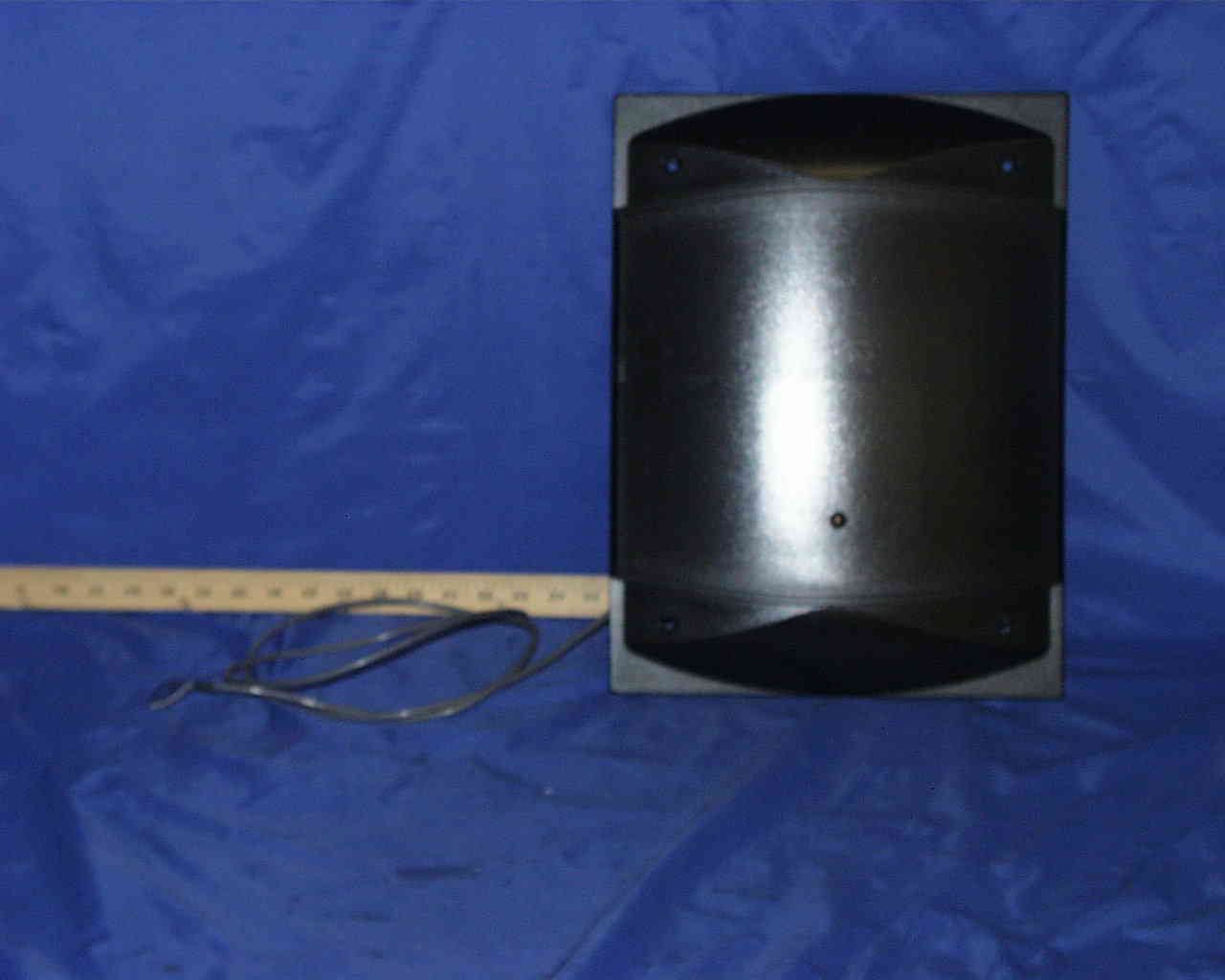
N42KERI2000RF Tag Reader
KERI Systems Inc.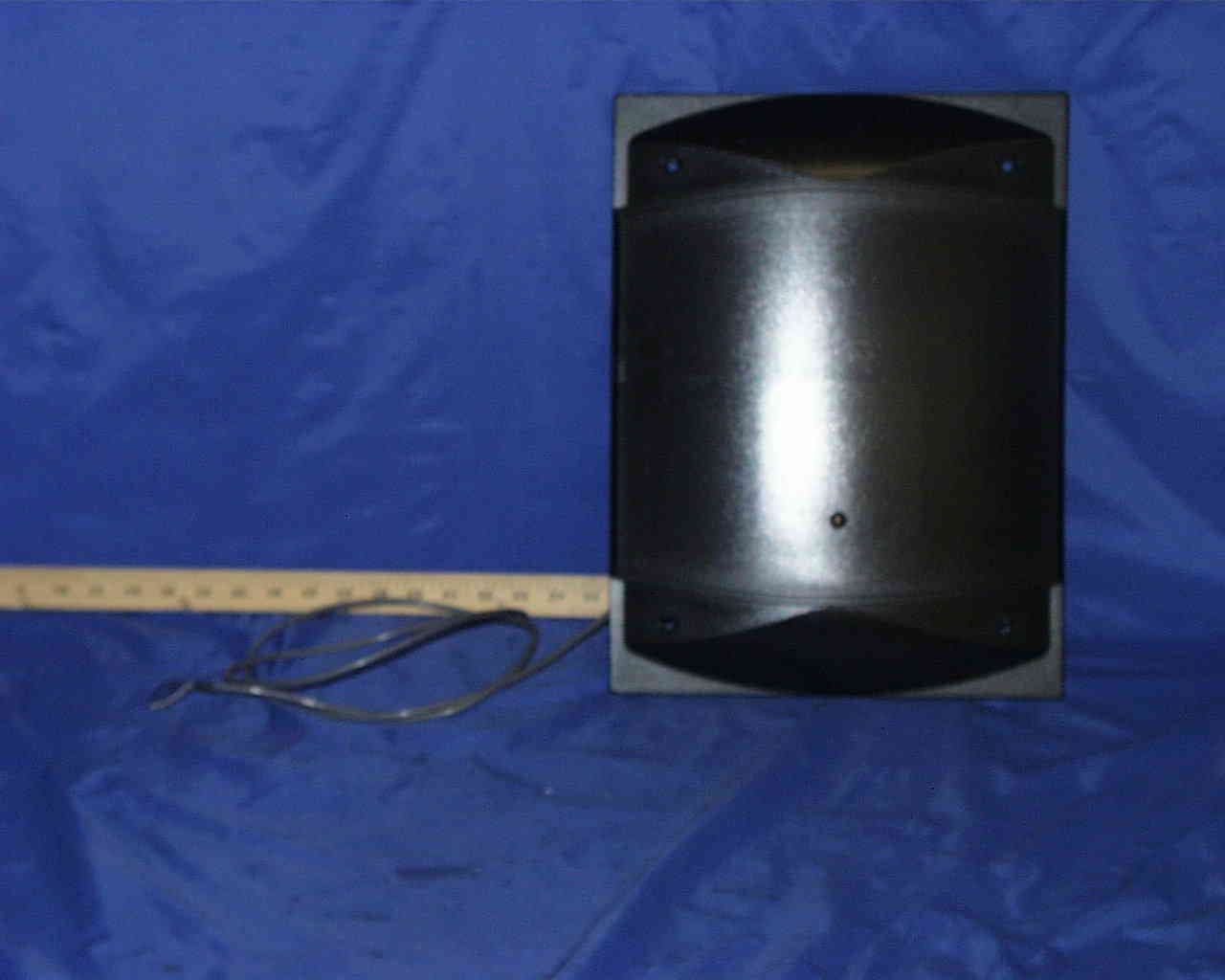
Click to zoom
Application Details
- Equipment Class
- DCD - Part 15 Low Power Transmitter Below 1705 kHz
- Date of Grant
- Sep 29, 1998
- Application Purpose
- Original Equipment
- Date of Application
- Aug 23, 1998
- Equipment Note
- RF Tag Reader
- Frequency Range
- 0.12500000 - 0.12500000
- Company
- KERI Systems Inc.
- Country
- United States
Documents & Files
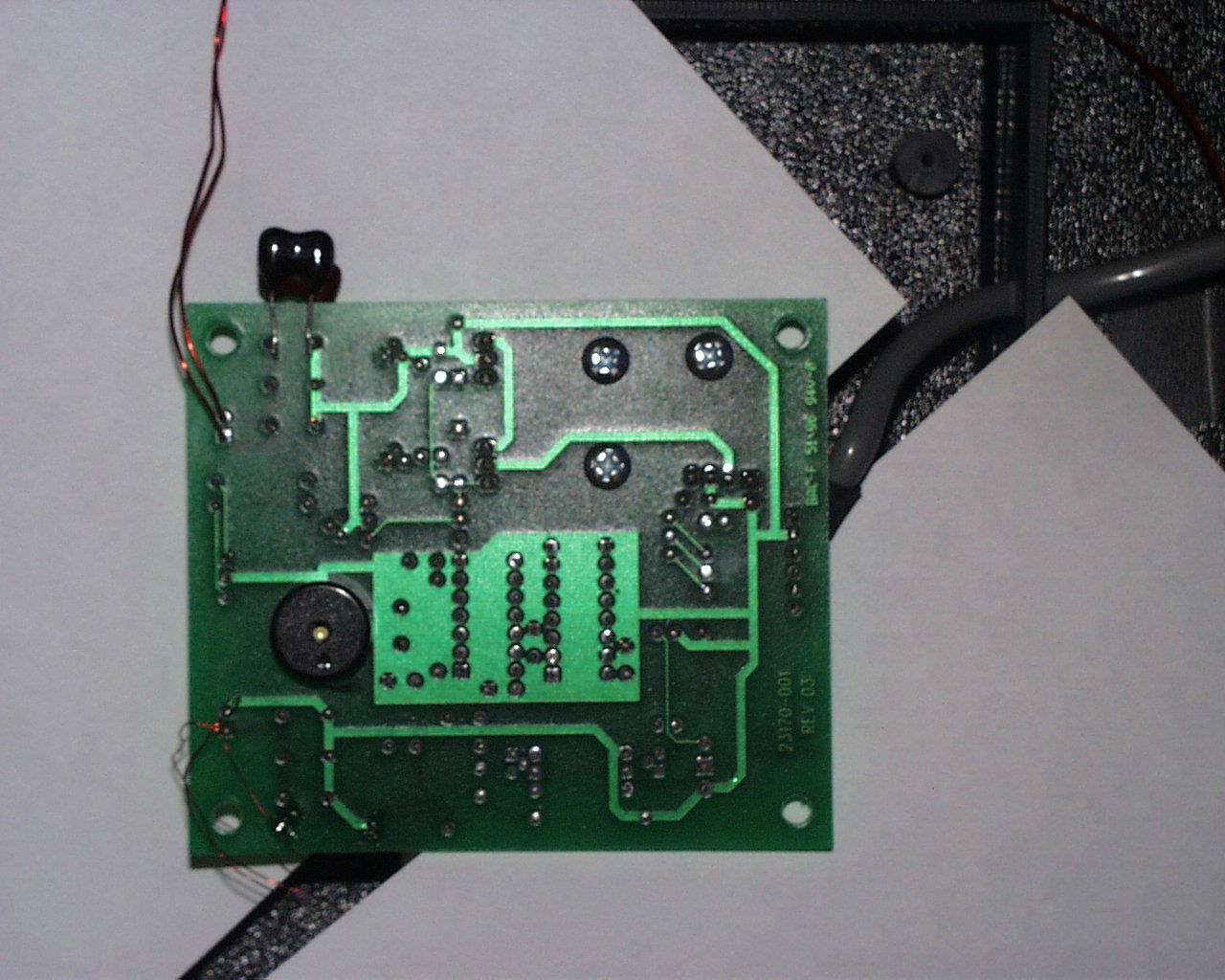
Document Text
Text extracted from the exhibit documents filed with the FCC. Open a document above to read the original.
Users Manual
1530 Old Oakland Road, Suite 10001827-001 Rev. D San Jose, CA 95112 USA (800) 260-5265 (408) 451-2520 FAX (408) 441-0309Page 1 of 6 MS-9000: MegaStar Reader The MS-9000 MegaStar Reader The MS-9000 MegaStar Reader is intended for installation in proximity applications where an extended read range is required. The reader provides an audio beeper and a multi colored LED to annunciate the reader's status when used on a PXL-250, PXL-100, or IntelliProx. • Amber – to indicate normal operation awaiting an access event • Green – to indicate a valid card has been presented or the door has been unlocked for access • Red – to indicate an invalid card has been presented or the door is in an alarm condition The MS-9000 MegaStar Reader is housed in a black, weatherproof, shock resistant package. The reader provides optimum performance when mounted at least ten inches away from metal surfaces; read range is reduced if the reader is mounted on or near metal surfaces. Specifications Dimensions • 8.50 inches High x 6.00 inches Wide x 0.75 inches Deep • 21.59 cm High x 15.24 cm Wide x 1.91 cm Deep Figure 1 – MS-9000 Dimensions Quick Start Guide MS-9000 12.15" 1.90" Drill Cable Access Hole 0.375" (3/8") 6.00" to Cable Hole Center 1.35" D12.00" W 16.00" H 1.60" 8.85" Mounting Holes - 4x LED 7.50" to Cable Hole Center 1530 Old Oakland Road, Suite 10001827-001 Rev. D San Jose, CA 95112 USA (800) 260-5265 (408) 451-2520 FAX (408) 441-0309Page 2 of 6 MS-9000: MegaStar Reader Operating Voltage • 12v to 24v DC @ 200 ma Cable Specifications • up to 100 feet using six conductor, shielded, stranded AWG 24 wire • up to 250 feet using six conductor, shielded, stranded AWG 22 wire • up to 500 feet using six conductor, shielded, stranded AWG 18 wire Mounting Instructions Five holes need to be drilled to mount the MegaStar Reader (see Figure 1 on page 1). One hole (0.375" – 3/8") accommodates the reader cable. Four holes are for mounting the reader on a wall surface (hole size is dependent upon the size of the mounting screw – a 1/4" screw or bolt is recommended). For parking or related applications, the MegaStar Reader can be mounted to a metal "goose- neck" stand, provided the mounting surface on the stand is 4 inches x 4 inches or smaller. This size restriction on the stand's mounting surface ensures the metal in the stand does not affect the operation of the Reader. If the stand's mounting surface is greater than 4 inches x 4 inches a mounting plate made of nonmetallic material is required between the stand's mounting surface and the Reader to provide the necessary distance between Reader and metal to ensure optimum read range. Connections The MegaStar Reader does not require configuration; there are no switches or jumpers to set. The MegaStar Reader is normally connected to a PXL-250, PXL-100, or IntelliProx, but can be connected to an alternative host controller/alarm panel through an IntelliProx used in its Wiegand input device mode. All connections needed to support the reader are made through the reader's cable. Please consult the tables on pages 2 and 3 for specific connection instructions. PXL-250 Connections The "A" reader connects to TB5, pins 1 through 6 (TB5 has a seventh pin, but no connection is made to that pin). The "B" reader connects to TB6, pins 1 through 6 (TB6 has a seventh pin, but no connection is made to that pin). Connecting to the PXL-250 – TB5 or TB6 Pin #FunctionWire Color 1Reader AntennaBlue 2BeeperGreen 3Reader PowerRed 4Reader GroundBlack 5Green LEDBrown 6Red LEDWhite 7no connection– 4ShieldSilver Figure 2 – PXL-250 Connections JP4 12V5V 13 Receiver Board Connectors to the Motherboard TB5 - "A" Reader on the Motherboard 1 2 3 4 5 6 7 TB6 - "B" Reader on the Receiver Board 1 2 3 4 5 6 7 Quick Start Guide MS-9000 1530 Old Oakland Road, Suite 10001827-001 Rev. D San Jose, CA 95112 USA (800) 260-5265 (408) 451-2520 FAX (408) 441-0309Page 3 of 6 MS-9000: MegaStar Reader Design 5 PXL-100 Connections The "A" reader connects to TB2, pins 14 through 19. The "B" reader connects to TB3, pins 20 through 25. Connecting to the PXL-100 – TB2 Pin #FunctionWire Color 14Green LEDBrown 15BeeperGreen 16Reader PowerRed 17Reader GroundBlack 18Reader AntennaBlue 19Red LEDWhite 17ShieldSilver Connecting to the PXL-100 – TB3 Pin #FunctionWire Color 20Green LEDBrown 21BeeperGreen 22Reader PowerRed 23Reader GroundBlack 24Reader AntennaBlue 25Red LEDWhite 23ShieldSilver Figure 3 – Design 5 PXL-100 Connections NOTE: Please contact customer support at Keri Systems for information regarding connecting a Reader to a Design 4 PXL-100. A Design 4 PXL-100 can be identified by the location of its power connection made at the middle of the left edge of the printed circuit board. IntelliProx Connections The reader is connected to TB1, pins 1 through 6. Connecting to the IntelliProx – TB1 Pin #FunctionWire Color 1Reader AntennaBlue 2BeeperGreen 3Green LEDBrown 4Red LEDWhite 5Reader PowerRed 6Reader GroundBlack 6ShieldSilver Figure 4 – IntelliProx Connections TB2 "A" Reader TB3 "B" Reader 20 21 22 23 24 25 14 15 16 17 18 19 S1 TB1 - Reader 123456 8 7 TB2 Quick Start Guide MS-9000 1530 Old Oakland Road, Suite 10001827-001 Rev. D San Jose, CA 95112 USA (800) 260-5265 (408) 451-2520 FAX (408) 441-0309Page 4 of 6 MS-9000: MegaStar Reader 24 VDC Power Option Instead of the 12 VDC power provided by the controller or IntelliProx unit, the MegaStar Reader can be powered by a 24 VDC linear, regulated power supply. The advantage to the 24 VDC supply is that the read range is increased by approximately 20%. Perform the following steps to use the 24 VDC power option. 1. Disconnect the power and ground leads from the controller or IntelliProx unit. 2. Connect the positive lead from the 24 VDC supply to the Red lead on the Reader cable. 3. Connect the negative lead from the 24 VDC supply to the Black lead on the Reader cable. 4. Connect the ground lead from the 24 VDC supply to the power ground on the controller or IntelliProx unit. • TB2, p…
Text truncated - open the document above for the full version.
Cover Letter(s)
tel: 650-726-1263 fax: 650-726-1252 internet: [email protected] Thomas N. CokeniasEMC & Radio Type Approvals Test & Consulting Services for Commercial, Military, International Compliance P.O. Box 1086 El Granada, CA 94018 7 September 1998 FCC Laboratory 7435 Oakland Mills Road Columbia, MD 21046 Attention: Applications Examiner/Reviewing Engineer Re: Request that portions of Part 15 Certification Application be kept Confidential Applicant: Keri Systems Inc. Equipment: RF ID Tag Reader System FCC ID: N42KERI2000 To whom it may concern: On behalf of my client Keri Systems Inc., request is made herein to keep the following portions of the referenced application confidential and unavailable for routine public review, as per the conditions of section 0.457 of the Rules: Schematics Block Diagrams Theory of operation Keri’s new product is the result of considerable research and development, and incorporates methodologies and circuitry that are innovative and unique. Disclosure of this information would result in competitors being able to obtain the benefits of Keri’s research and development without incurring the accompanying cost, resulting in an unfair competitive advantage. The required fee for this request for confidentiality has been paid in a separate action. If you have questions or need further information, please contact the undersigned. Sincerely, tel: 650-726-1263 fax: 650-726-1252 internet: [email protected] THOMAS N. COKENIAS Agent for Keri Systems Inc.
Cover Letter(s)
September 21, 1998 Federal Communications Commission Gentlemen: This letter is to inform you that Mr. Tom Cokenias is authorized to represent Keri Systems, Incorporated in all FCC matters pertaining to the pending applications for FCC Certification of equipment under the filing numbers, N42KERI1000 and N42KERI2000. Thank you for your cooperation in this matter. Russel E. Walker Special Projects Engineer
ID Label/Location Info
KERI SYSTEMS INC. LABEL PLACEMENT, FCC ID: N42KERI2000 back panel of unit label KERI SYSTEMS INC. Proposed Label format Size: 2.25 in x 1.5 in (approx.) This device complies with Part 15 of the FCC rules. Operation is subject to the following two conditions: (1) This device may not cause harmful interference, And (2) this device must accept any interference that may cause undesired operation. Patents: FCC ID: N42KERI2000 Model: S/N: Manual: Power: Format::
Test Report
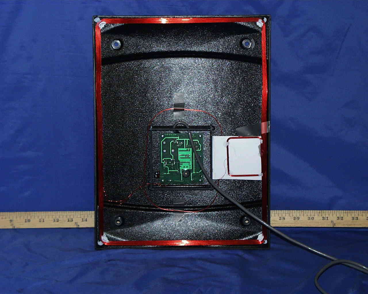
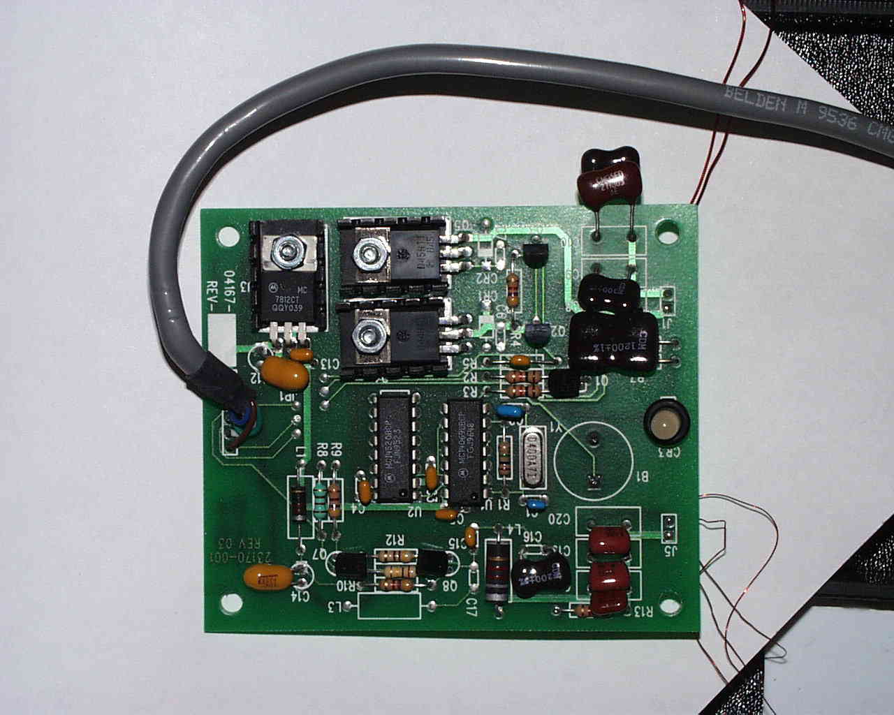
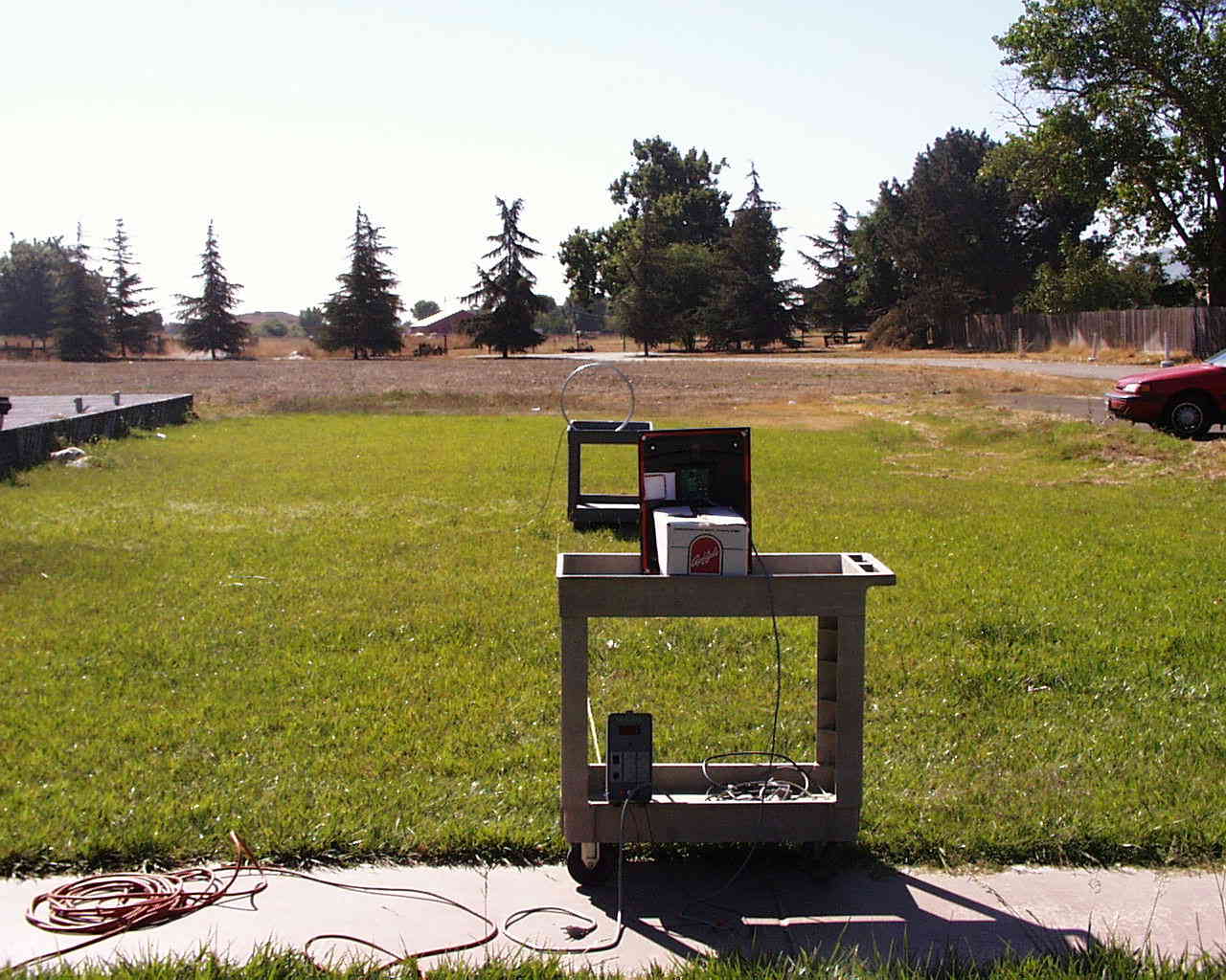
Keri Systems Inc. page 1 of 9 pages FCC ID: N42KERI2000 LIST OF EXHIBITS EXHIBIT AUser Manual EXHIBIT B:Schematic Diagram(s) Block Diagram(s) EXHIBIT C:Modifications to EUT to Meet EMI Requirements EXHIBIT D:Photographs of EUT and FCC ID Label EXHIBIT E:Emissions Test Report Keri Systems Inc. page 2 of 9 pages FCC ID: N42KERI2000 EXHIBIT A: User Manual: separate electronic exhibit Keri Systems Inc. page 3 of 9 pages FCC ID: N42KERI2000 EXHIBIT B: Schematic Diagram(s) Block Diagram(s) -separate electronic exhibits Keri Systems Inc. page 4 of 9 pages FCC ID: N42KERI2000 EXHIBIT C: Modifications to EUT to Meet EMI Requirements [x] None[ ] Description attached Keri Systems Inc. page 5 of 9 pages FCC ID: N42KERI2000 EXHIBIT D: Photographs of EUT and FCC ID Label - separate electronic submissions Keri Systems Inc. page 6 of 9 pages FCC ID: N42KERI2000 EXHIBIT E: Emissions Test Report Keri Systems Inc. page 7 of 9 pages FCC ID: N42KERI2000 EMISSIONS TEST REPORT FOR A LOW POWER TRANSMITTER I. GENERAL INFORMATION Requirement:Federal Communications Commission (FCC) Certification under FCC Rule Part 15 (Technical Requirements: 15.205, 15.209) Applicant:Keri Systems Inc. 1530 Old Oakland Road, Suite 100 San Jose, CA 95112 Product ID:FCC ID: N42KERI2000 II. DESCRIPTION OF EQUIPMENT UNDER TEST (EUT) The Keri Systems MS9000 is a tag reader employing a low level, 125 kHz RF magnetic field to activate a microchip embedded in a small plastic tag.. The activated chip transmits a unique pre-coded identification (ID) number back to the receiver. The EUT is DC powered only and exempt from the AC line conducted requirements of 15.207. III. TEST LOCATION All emissions tests were performed at: Compliance Consulting Services 1366 Bordeaux Avenue Sunnyvale, CA 94086 CCS is a NVLAP accredited test facility with 3 open air test sites (OATS). Three meter and 10 meter site attenuation data and test site descriptions are on file with the FCC. Radiated emissions testing was performed on a large open grassy area located between two of the sites. The open area extends for more than 200 meters. IV. TEST PROCEDURES AND RESULTS Radiated Emissions: Radiated emissions measurements were performed at several intermediate distances less than 300 m. Data points so obtained were plotted on semilog graph paper, and a best-fit straight line was extended to the 300 m mark of the graph, and the extrapolated emissions level was compared to the limit for each frequency. Data was taken up to 30 MHz. For each test location: Keri Systems Inc. page 8 of 9 pages FCC ID: N42KERI2000 1. The EUT was placed on a plastic cart approximately 90 cm above ground level. An RF tag was placed in the field of the EUT to verify proper EUT operation. The tag was left in place for the duration of the test. Refer to Figure 1 for test set-up. 2. The EUT was rotated, raised, and lowered in order to maximize received emissions. Maximum received emissions were achieved when the EUT loop antenna was in the same plane and at the same height as the receiving active loop antenna. 3. The reading for each frequency of emission was recorded and plotted on semilog graph paper. Figure 1. Radiated Emissions Test Set-up loop antenna EUT 20m 10m 6m 3m 1m DC Power supply spectrum analyzer AC Test Results PASS. See attached spread sheet and extrapolated data graph. Conducted Emissions: NOT APPLICABLE - DC OPERATION ONLY Equipment Used to Perform Tests Description Manufacturer Model S/N AnalyzerHP85683207A01294 Active Loop AntennaEMCO65029202-2722 V. CERTIFICATION OF DATA All radiated and conducted measurements, for both intentional and unintentional radiator portion of the EUT, were performed, or were witnessed and supervised, by the undersigned. To the best of his Keri Systems Inc. page 9 of 9 pages FCC ID: N42KERI2000 knowledge and belief, test equipment calibrations, test procedures, and test data were accurate and as reported here. T.N. COKENIAS7 September 1998 Agent for Keri Systems Inc. Keri Systems Inc. page 10 of 9 pages FCC ID: N42KERI2000 TABLE 1: Radiated EmissionsTest Date: 24 August 1998 Company: Keri Systems Inc. Model: MS9000 (12”x 16” coil) FCC ID: N42KERI2000 F(kHz) Dist. (ft) Reading, dBuV AF, dB Amp, dB Total,dBuV/m 1256111.451-25137.4 1097.851-25123.8 2080.751-25106.7 3070.351-25 96.3
Contact Information
Applicant
Veronica De Leon(Quality Assurance Engineer)
Technical Contact
T.N. Cokenias ConsultingThomas N Cokenias
[email protected]650-726-1263
El Granada, California · United States
Non-Technical Contact
T.N. Cokenias ConsultingThomas N Cokenias
[email protected]650-726-1263
Test Firm
Compliance Certification Services IncSteve Cheng
Technical Specifications
| # | Rule Parts | Frequency Range | Power Output |
|---|---|---|---|
| 1 | 15C | 0.125 MHz - 0.125 MHz | - |
Other Applications from KERI Systems Inc.
N42KERI1000
Nov 01, 1998Tag Reader
Equipment Class
DCD - Part 15 Low Power Transmitter Below 1705 kHz