Text extracted from the exhibit documents filed with the FCC. Open a document above to read the original.
1 Wireless LAN Card(E1600-12A) Honda Engineering Co.,Ltd Wireless LAN Card ( (( (E1600-12A) )) ) Manual Approval H.Hashimoto Check T.Takasaka Version 0.1 MakeDate K.Sakai2011/11/10 Copyright (C) Honda Engineering Co., Ltd. 2011 2 Wireless LAN Card(E1600-12A) Honda Engineering Co.,Ltd Version改変履歴 THIS DOCUMENT CONTAINS PROPRIETARY INFORMATION AND IS SUBMITTED IN CONFIDENCE TO BE USED SOLELY FOR THE PURPOSE FOR WHICH IT IS FURNISHED. THIS DOCUMENT IS NOT TO BE REPRODUCED, TRANSMITTED, DISCLOSED OR USED OTHERWISE IN WHOLE OR IN PART WITHOUT PRIOR WRITTEN AUTHORIZATION FROM HONDA ENGINEERING AND HONDA MOTORS LIMITED. THIS DOCUMENT IS TO BE RETURNED UPON REQUEST. New0.12011/11/10 DescriptionVersionDate 3 Wireless LAN Card(E1600-12A) Honda Engineering Co.,Ltd FCC CAUTION Changes or modifications not expressly approved by the party responsible for compliance could void the user’s authority to operate the equipment. Note: This equipment has been tested and found to comply with the limits for a Class B digital device, pursuant to part 15 of the FCC Rules. These limits are designed to provide reasonable protection against harmful interference in a residential installation. This equipment generates, uses and can radiate radio frequency energy and, if not installed and used in accordance with the instructions, may cause harmful interference to radio communications. However, there is no guarantee that interference will not occur in a particular installation. If this equipment does cause harmful interference to radio or television reception, which can be determined by turning the equipment off and on, the user is encouraged to try to correct the interference by one or more of the following measures: —Reorient or relocate the receiving antenna. —Increase the separation between the equipment and receiver. —Connect the equipment into an outlet on a circuit different from that to which the receiver is connected. —Consult the dealer or an experienced radio/TV technician for help. This transmitter must not be co-located or operated in conjunction with any other antenna or transmitter. 4 Wireless LAN Card(E1600-12A) Honda Engineering Co.,Ltd This device complies with Part 15 of FCC Rules and Industry Canada licence- exempt RSS standard(s). Operation is subject to the following two conditions: (1) this device may not cause interference, and (2) this device must accept any interference, including interference that may cause undesired operation of this device. Le présent appareil est conforme aux la partie 15 des règles de la FCC et CNR d'Industrie Canada applicables aux appareils radio exempts de licence. L'exploitation est autorisée aux deux conditions suivantes : (1) l'appareil ne doit pas produire de brouillage, et (2) l'utilisateur de l'appareil doit accepter tout brouillage radioélectrique subi, même sile brouillage est susceptible d'en compromettre le fonctionnement. The available scientific evidence does not show that any health problems are associated with using low power wireless devices. There is no proof, however, that these low power wireless devices are absolutely safe. Low power Wireless devices emit low levels of radio frequency energy (RF) in the microwave range while being used. Whereas high levels of RF can produce health effects (by heating tissue), exposure of low-level RF that does not produce heating effects causes no known adverse health effects. Many studies of low-level RF exposures have not found any biological effects. Some studies have suggested that some biological effects might occur, but such findings have not been confirmed by additional research. [Wireless LAN Card(E1600-12A)] has been tested and found to comply with FCC radiation exposure limits set forth for an uncontrolled environment and meets the FCC radio frequency (RF) Exposure Guidelines in Supplement C to OET65. The maximum SAR levels tested for [Wireless LAN Card(E1600-12A)] has been shown to be [SAR 1.13W/kg] W/kg at Body. 5 Wireless LAN Card(E1600-12A) Honda Engineering Co.,Ltd The available scientific evidence does not show that any health problems are associated with using low power wireless devices. There is no proof, however, that these low power wireless devices are absolutely safe. Low power Wireless devices emit low levels of radio frequency energy (RF) in the microwave range while being used. Whereas high levels of RF can produce health effects (by heating tissue), exposure of low-level RF that does not produce heating effects causes no known adverse health effects. Many studies of low-level RF exposures have not found any biological effects. Some studies have suggested that some biological effects might occur, but such findings have not been confirmed by additional research. [Wireless LAN Card(E1600-12A)] has been tested and found to comply with FCC/IC radiation exposure limits set forth for an uncontrolled environment and meets the FCC radio frequency (RF) Exposure Guidelines in Supplement C to OET65 and RSS-102 of the IC radio frequency (RF) Exposure rules. The maximum SAR levels tested for [Wireless LAN Card(E1600-12A)] has been shown to be [SAR 1.13W/kg] W/kg at Body. Les connaissances scientifiques dont nous disposons n’ont mis en évidence aucun problème de santéassocié àl’usage des appareils sans fil àfaible puissance. Nous ne sommes cependant pas en mesure de prouver que ces appareils sans fil à faible puissance sont entièrement sans danger. Les appareils sans fil àfaible puissance émettent une énergie radioélectrique (RF) très faible dans le spectre des micro-ondes lorsqu’ils sont utilisés. Alors qu’une dose élevée de RF peut avoir des effets sur la santé(en chauffant les tissus), l’exposition àde faibles RF qui ne produisent pas de chaleur n’a pas de mauvais effets connus sur la santé. De nombreuses études ont étémenées sur les expositions aux RF faibles et n’ont découvert aucun effet biologique. Certaines études ont suggéréqu’il pouvait y avoir certains effets biologiques, mais ces résultats n’ont…
Text truncated - open the document above for the full version.
This wireless LAN card is for internal use by only dedicated employee in factory and installed with PDA like following photo indicated. Data of equipment in factory is transferred using this wireless LAN card. Therefore there is noinstallation manual. Honda Engineering Co., Ltd. N0.6-1, Hagadai, Haga-Machi, Haga-Gun Tochigi Pref, 321-3395 Japan Telephone +81 28 677-6946 Fax +81 28 677-6980
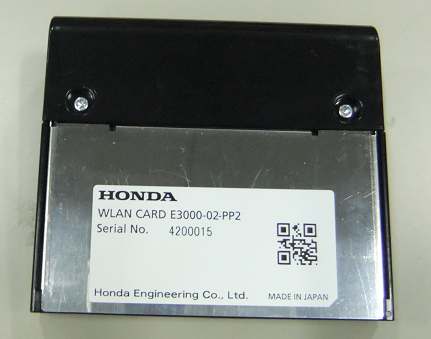
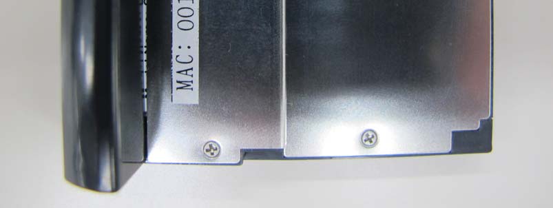
External Photo Honda Engineering Co., Ltd. FCC ID: N43E160012A IC: 10350A-E160012A Front Rear External Photo Honda Engineering Co., Ltd. FCC ID: N43E160012A IC: 10350A-E160012A Top Bottom External Photo Honda Engineering Co., Ltd. FCC ID: N43E160012A IC: 10350A-E160012A Right Left
42 45 40 34 32 42 32 12 42 Model:E1600-12AMAC:XXXXXXXXXXXX FCC ID: N43E160012AIC: 10350A-E160012A 007-AA0069 R XXXXXXXXXXXXX Made in Japan
Photo Honda Engineering Co., Ltd. Front Rear Photo Honda Engineering Co., Ltd. Photo Honda Engineering Co., Ltd. Antenna Location
Test report No. : 32CE0083-SH-01-A Page : 2 of 55 Issued date : June 11, 2012 FCC ID : N43E160012A UL Japan, Inc. Shonan EMC Lab. 1-22-3 Megumigaoka, Hiratsuka-shi, Kanagawa-ken, 259-1220 JAPAN Telephone : +81 463 50 6400 Facsimile : +81 463 50 6401 REVISION HISTORY Original Test Report No.: 32CE0083-SH-01-A Revision Test report No. Date Page revised Contents - (Original) 32CE0083-SH-01-A June 11, 2012 - - 1 32CE0083-SH-01-A July 9, 2012 p.1-2 Update p.4 “Operation temperature range” changed, “-30 to +75 deg.C.” to “0 to 45deg.C”. p.48 Page 48 data sheet was replaced. Revised date : July 9, 2012 Test report No. : 32CE0083-SH-01-A Page : 3 of 55 Issued date : June 11, 2012 FCC ID : N43E160012A UL Japan, Inc. Shonan EMC Lab. 1-22-3 Megumigaoka, Hiratsuka-shi, Kanagawa-ken, 259-1220 JAPAN Telephone : +81 463 50 6400 Facsimile : +81 463 50 6401 Contents Page SECTION 1: Customer information ..................................................................................... 4 SECTION 2: Equipment under test (E.U.T.) ....................................................................... 4 SECTION 3: Test specification, procedures & results ......................................................... 5 SECTION 4: Operation of E.U.T. during testing ................................................................. 8 SECTION 5: Conducted emission ......................................................................................... 9 SECTION 6: 6dB bandwidth & Occupied bandwidth (99%) ............................................. 9 SECTION 7: Maximum peak output power ....................................................................... 10 SECTION 8: Spurious emission (Antenna port conducted) .............................................. 10 SECTION 9: Radiated emission .......................................................................................... 11 SECTION 10: Peak Power density ...................................................................................... 12 Contents of APPENDIXES ................................................................................................... 13 APPENDIX 1: Test data ...................................................................................................... 14 APPENDIX 2: Test instruments .......................................................................................... 52 APPENDIX 3: Photographs of test setup ............................................................................ 53 Test report No. : 32CE0083-SH-01-A Page : 4 of 55 Issued date : June 11, 2012 FCC ID : N43E160012A UL Japan, Inc. Shonan EMC Lab. 1-22-3 Megumigaoka, Hiratsuka-shi, Kanagawa-ken, 259-1220 JAPAN Telephone : +81 463 50 6400 Facsimile : +81 463 50 6401 SECTION 1: Customer information Company Name : Honda Engineering Co., Ltd. Address : 6-1 Hagadai, Haga-machi, Haga-gun, Tochigi, 321-3395 Japan Telephone Number : +81-28-677-6946 Facsimile Number : +81-28-677-6946 Contact Person : Kazumori Sakai SECTION 2: Equipment under test (E.U.T.) 2.1 Identification of E.U.T. Type of Equipment : Wireless LAN Card Model No. : E1600-12A Serial No. : MAC:001723146B56 Rating : DC3.3V Receipt Date of Sample : January 19, 2012 Country of Mass-production : Japan Condition of EUT : Production prototype (Not for Sale: This sample is equivalent to mass-produced items.) Modification of EUT : No modification by the test lab. 2.2 Product description Model: E1600-12A (referred to as the EUT in this report) is a Wireless LAN Card. Clock frequency(ies) in the system : 20MHz Radio specification Equipment type : Transceiver Frequency of operation : 2412-2462MHz Bandwidth & channel spacing: 20MHz & 5MHz Type of modulation : DSSS: CCK,DQPSK, DBPSK OFDM: 16QAM, 64QAM, QPSK, BPSK Antenna type : Chip antenna x2 (Main, AUX) Antenna connector type : U.FL Antenna gain with cable loss : 0.64dBi ITU code : D1D, G1D Operation temperature range : 0 to +45 deg.C. FCC 15.31 (e) The Wireless Module is provided with stable power supply DC 3.3V from the host device, therefore, the equipment complies power supply regulation. FCC 15.203 It is impossible for end users to replace the antenna, because the antenna is mounted inside of the EUT. Therefore, the equipment complies with the antenna requirement. Revised date : July 9, 2012 Test report No. : 32CE0083-SH-01-A Page : 5 of 55 Issued date : June 11, 2012 FCC ID : N43E160012A UL Japan, Inc. Shonan EMC Lab. 1-22-3 Megumigaoka, Hiratsuka-shi, Kanagawa-ken, 259-1220 JAPAN Telephone : +81 463 50 6400 Facsimile : +81 463 50 6401 SECTION 3: Test specification, procedures & results 3.1 Test specification Test specification : FCC Part 15 Subpart C: 2012, final revised on March 30, 2012 and effective April 30, 2012 Title : FCC 47CFR Part15 Radio Frequency Device Subpart C Intentional Radiators Section 15.207 Conducted limits Section 15.209 Radiated emission limits, general requirements Section 15.247 Operation within the bands 902-928MHz, 2400-2483.5MHz, and 5725-5850MHz * The revision on March 30, 2012 does not affect the test specification applied to the EUT. The EUT complies with FCC Part 15 Subpart B. Refer to the test report 32CE0083-SH-01-C. 3.2 Procedures & Results Item Test Procedure SpecificationRemarksDeviationWorst Margin Results Conducted emission ANSI C63.4:2009 7. AC powerline conducted emission measurements FCC 15.207 - N/A 11.1dB Freq.: 0.40994MHz Detector: Average Phase: N Mode: Tx 2412MHz, IEEE 802.11g Complied 6dB bandwidth ANSI C63.4:2009 13. Measurement of intentional radiators FCC 15.247 (a)(2) & 15.209 ConductedN/A * See data Complied Maximum peak output power ANSI C63.4:2009 13. Measurement of intentional radiators FCC 15.247 (b)(3) & 15.209 ConductedN/A Complied Spurious emission & Restricted band edges ANSI C63.4:2009 13. Measurement of intentional radiators FCC 15.109, 15.247 (d) & 15.209 Conducted / Radiated N/A 3.1dB Freq.: 4874.000MHz Detector: Average Polarization: Horizontal Mode: Tx 2437MHz, IEEE 802.11b Compl…
Text truncated - open the document above for the full version.
Test report No. : 32CE0083-SH-01-D Page : 2 of 47 Issued date : June 13, 2012 FCC ID : N43E160012A UL Japan, Inc. Shonan EMC Lab. 1-22-3 Megumigaoka, Hiratsuka-shi, Kanagawa-ken, 259-1220 JAPAN Telephone: +81 463 50 6400 / Facsimile: +81 463 50 6401 CONTENTS PAGE SECTION 1: Customer information ................................................................................... 3 SECTION 2: Equipment under test (EUT) ......................................................................... 3 SECTION 3: Test specification, procedures and results ................................................... 4 3.1 Test specification ................................................................................................................. 4 3.2 Exposure limit ..................................................................................................................... 4 3.3 Procedure and result ............................................................................................................ 4 3.4 Test location ........................................................................................................................ 4 3.5 Confirmation before SAR testing ........................................................................................ 5 3.6 Confirmation after SAR testing ........................................................................................... 5 3.7 Test setup of EUT and SAR measurement procedure ......................................................... 6 SECTION 4: Operation of EUT during testing .................................................................. 6 4.1 Operating modes for SAR testing ........................................................................................ 6 SECTION 5: Uncertainty assessment (SAR measurement) .............................................. 7 SECTION 6: Confirmation before testing .......................................................................... 7 6.1 Assessment for the conducted power of EUT ..................................................................... 7 SECTION 7: Measurement results ...................................................................................... 8 7.1 SAR test results ................................................................................................................... 8 Contents of appendixes APPENDIX 1: Photographs of test setup .............................................................................. 9 Appendix 1-1 Photograph of EUT and antenna position ........................................................................... 9 Appendix 1-3 EUT and support equipment ................................................................................................ 10 Appendix 1-4 Photograph of test setup ...................................................................................................... 11 APPENDIX 2: SAR Measurement data ................................................................................. 13 Appendix 2-1 Evaluation procedure ........................................................................................................... 13 Appendix 2-2 Measurement data................................................................................................................ 14 APPENDIX 3: Test instruments ............................................................................................. 22 Appendix 3-1 Equipment used ................................................................................................................... 22 Appendix 3-2 Dosimetry assessment setup ................................................................................................ 23 Appendix 3-3 Configuration and peripherals ............................................................................................. 23 Appendix 3-4 System components ............................................................................................................. 24 Appendix 3-5 Test system specification ..................................................................................................... 25 Appendix 3-6 Simulated tissues composition ............................................................................................ 25 Appendix 3-7 Simulated tissues parameter confirmation ........................................................................... 26 Appendix 3-8 System check data ............................................................................................................... 26 Appendix 3-9 System check measurement data ......................................................................................... 27 Appendix 3-10 System check uncertainty .................................................................................................... 27 Appendix 3-11 Calibration certificate: Dipole (D2450V2) .......................................................................... 28 Appendix 3-12 Calibration certificate: E-Field Probe (EX3DV4) ............................................................... 36 Appendix 3-13 References ........................................................................................................................... 47 REVISION HISTORY Revision Test report No. DatePage revisedContents Original 32CE0083-SH-01-D June 13, 2012-- -R01 32CE0083-SH-01-D July 6, 20122, 22 Updated the remarks of the equipment list. *. By issue of new revision report, the report of an old revision becomes invalid. Reviseddate : July 6, 2012 Test report No. : 32CE0083-SH-01-D Page : 3 of 47 Issued date : June 13, 2012 FCC ID : N43E160012A UL Japan, Inc. Shonan EMC Lab. 1-22-3 Megumigaoka, Hiratsuka-shi, Kanagawa-ken, 259-1220 JAPAN Telephone: +81 463 50 6400 / Facsimile: +81 463 50 6401 SECTION 1: Customer information Company Name Honda Engineering Co., Ltd. Brand Name - Address 6-1 Hagadai, Hagamachi, Hagagun, Tochigi, 321-3395Japan Telephone Number +81-2…
Text truncated - open the document above for the full version.
Test report No. : 32CE0083-SH-01-D Page : 13 of 47 Issued date : June 13, 2012 FCC ID : N43E160012A UL Japan, Inc. Shonan EMC Lab. 1-22-3 Megumigaoka, Hiratsuka-shi, Kanagawa-ken, 259-1220 JAPAN Telephone: +81 463 50 6400 / Facsimile: +81 463 50 6401 APPENDIX 2: SAR Measurement data Appendix 2-1: Evaluation procedure The SAR evaluation was performed with the following procedure: Step 1: Measurement of the E-field at a fixed location above the central position of flat phantom was used as a reference value for assessing the power drop. Step 2: The SAR distribution at the exposed side of head or body position was measured at a distance of each device from the inner surface of the shell. The area covered the entire dimension of the antenna of EUT and suitable horizontal grid spacing of EUT. Based on these data, the area of the maximum absorption was determined by splines interpolation. Step 3: Around this point found in the Step 2 (area scan), a volume of 30mm(X axis)30mm(Y axis)30mm(Z axis) was assessed by measuring 777 points under 3GHz. And for any secondary peaks found in the Step2 which are within 2dB of maximum peak and not with this Step3 (Zoom scan) is repeated. On the basis of this data set, the spatial peak SAR value was evaluated under the following procedure: (1) The data at the surface were extrapolated, since the center of the dipoles is 1mm away from the tip of the probe and the distance between the surface and the lowest measuring point is 2mm. The extrapolation was based on a least square algorithm [4]. A polynomial of the fourth order was calculated through the points in z-axes. This polynomial was then used to evaluate the points between the surface and the probe tip. (2) The maximum interpolated value was searched with a straightforward algorithm. Around this maximum the SAR values averaged over the spatial volumes (1g or 10g) were computed by the 3D-Spline interpolation algorithm. The 3D-Spline is composed of three one-dimensional splines with the “Not a knot"-condition (in x, y and z-directions) [4], [5]. The volume was integrated with the trapezoidal-algorithm. One thousand points (101010) were interpolated to calculate the average. (3) All neighboring volumes were evaluated until no neighboring volume with a higher average value was found. Step 4: Re-measurement of the E-field at the same location as in Step 1 for the assessment of the power drift. Step 5: Repeat Step 1-Step 4 with other condition or/and setup of EUT. Test report No. : 32CE0083-SH-01-D Page : 14 of 47 Issued date : June 13, 2012 FCC ID : N43E160012A UL Japan, Inc. Shonan EMC Lab. 1-22-3 Megumigaoka, Hiratsuka-shi, Kanagawa-ken, 259-1220 JAPAN Telephone: +81 463 50 6400 / Facsimile: +81 463 50 6401 Appendix 2-2: Measurement data Step 1: Change the channels Step 1-1: 2437MHz (ch.6) / 11b(1Mbps), Front-antenna (separation distance: 0mm) EUT: Wireless LAN Card; Type: E1600-12A; Serial: 001723146B56 (Mac.id) Communication System: IEEE 802.11b(1Mbps, DBPSK/DSSS); Frequency: 2437 MHz; Crest Factor: 1.0 Medium: M2450; Medium parameters used: f = 2437 MHz; σ = 1.98 S/m; ε r = 50.3; ρ = 1000 kg/m 3 DASY4 Configuration: - Probe: EX3DV4 - SN3679; ConvF(7.34, 7.34, 7.34); Calibrated: 2011/05/19 - Sensor-Surface: 2mm (Mechanical Surface Detection) - Electronics: DAE4 Sn626; Calibrated: 2012/02/15 - Phantom: ELI 4.0; Type: QDOVA001BA; Serial: 1059; Phantom section: Flat Section - Measurement SW: DASY4, V4.7 Build 80; Postprocessing SW: SEMCAD, V1.8 Build 184 fcc1,frt-ant&touch(d0),11b(1m),m2437(6)/ Area Scan:120x120,15 (9x9x1): Measurement grid: dx=15mm, dy=15mm; Maximum value of SAR (measured) = 1.03 mW/g Area Scan:120x120,15 (81x81x1): Measurement grid: dx=15mm, dy=15mm; Maximum value of SAR (interpolated) = 1.56 mW/g Zoom Scan:30x30x30,5 (7x7x7)/Cube 0: Measurement grid: dx=5mm, dy=5mm, dz=5mm; Reference Value = 24.2 V/m; Power Drift = 0.146 dB, Maximum value of SAR (measured) = 1.89 mW/g Peak SAR (extrapolated) = 2.95 W/kg SAR(1 g) = 1.11 mW/g; SAR(10 g) = 0.413 mW/g Remarks: *. Date tested: 2012/04/09; Tested by: Hiroshi Naka; Tested place:No.7 shielded room, *.liquid depth: 154mm; Position: distance of EUT to phantom: 0mm (2mm to liquid); ambient: 24.9 deg.C. / 40 %RH, *.liquid temperature: 22.4(start)/22.4(end)/22.6(in check) deg.C.; *.White cubic: zoom scan area, Red cubic: big=SAR(10g )/small=SAR(1g) Test report No. : 32CE0083-SH-01-D Page : 15 of 47 Issued date : June 13, 2012 FCC ID : N43E160012A UL Japan, Inc. Shonan EMC Lab. 1-22-3 Megumigaoka, Hiratsuka-shi, Kanagawa-ken, 259-1220 JAPAN Telephone: +81 463 50 6400 / Facsimile: +81 463 50 6401 Appendix 2-2: Measurement data Step 1: Change the channels Step 1-2: 2412MHz (ch.1) / 11b(1Mbps), Front-antenna (separation distance: 0mm) EUT: Wireless LAN Card; Type: E1600-12A; Serial: 001723146B56 (Mac.id) Communication System: IEEE 802.11b(1Mbps, DBPSK/DSSS); Frequency: 2412 MHz; Crest Factor: 1.0 Medium: M2450; Medium parameters used: f = 2412 MHz; σ = 1.95 S/m; ε r = 50.5; ρ = 1000 kg/m 3 DASY4 Configuration: - Probe: EX3DV4 - SN3679; ConvF(7.34, 7.34, 7.34); Calibrated: 2011/05/19 - Sensor-Surface: 2mm (Mechanical Surface Detection) - Electronics: DAE4 Sn626; Calibrated: 2012/02/15 - Phantom: ELI 4.0; Type: QDOVA001BA; Serial: 1059; Phantom section: Flat Section - Measurement SW: DASY4, V4.7 Build 80; Postprocessing SW: SEMCAD, V1.8 Build 184 fcc2,frt-ant&touch(d0),11b(1m),m2412(1)/ Area Scan:90x90,15 (7x7x1): Measurement grid: dx=15mm, dy=15mm; Maximum value of SAR (measured) = 1.09 mW/g Area Scan:90x90,15 (61x61x1): Measurement grid: dx=15mm, dy=15mm; Maximum value of SAR (interpolated) = 1.61 mW/g Zoom Scan:30x30x30,5 (7x7x7)/Cube 0: Measurement grid: dx=5mm, dy=5mm, dz=5mm; Reference Value = 23.3 V/m; Power Drift = -0.149 dB, Maximum value of SAR (measured) = 1.79 mW/g Peak SAR (extrapolated) = 2.71 W/kg SAR(1 g) = 1.09 mW/g; SAR(10 g) = 0.427 mW/g Remarks: *. Date tested: 2012/04/09; Tested by: Hiroshi Naka; Tested place:No.7 shielded room, *.liq…
Text truncated - open the document above for the full version.
Test report No. : 32CE0083-SH-01-D Page : 9 of 47 Issued date : June 13, 2012 FCC ID : N43E160012A UL Japan, Inc. Shonan EMC Lab. 1-22-3 Megumigaoka, Hiratsuka-shi, Kanagawa-ken, 259-1220 JAPAN Telephone: +81 463 50 6400 / Facsimile: +81 463 50 6401 APPENDIX 1: Photographs of EUT and SAR test setup Appendix 1-1: Photograph of EUT and antenna position Disassembling (1) with housing Disassembling (2) without housing Antenna information Chip antenna PCB Coaxial cable U.FL connector Soldering Main antenna Auxantenna Main Aux Left Right Front -antenna Bottom Rear Top Main antenna Aux antenna Front Test report No. : 32CE0083-SH-01-D Page : 10 of 47 Issued date : June 13, 2012 FCC ID : N43E160012A UL Japan, Inc. Shonan EMC Lab. 1-22-3 Megumigaoka, Hiratsuka-shi, Kanagawa-ken, 259-1220 JAPAN Telephone: +81 463 50 6400 / Facsimile: +81 463 50 6401 Appendix 1-2: EUT and support equipment Description of EUT and Support Equipment No. Item Model numberSerial numberManufacturerRemark A Wireless LAN Card E1600-12A 001723146B56(Mac.id)Honda EngineeringCo., Ltd. EUT. B Pocket PC iPAQ hx4700 00039-081-395-425 HP Support equipment. Typical platform for the EUT. C Docking Station HSTNH-F02X E89760AZDRB3SF HP Support equipment. (These items were not used for SAR test) D AC Adaptor HP-AC010L63 584BA01YMR77DJ HP List of cables used No. Name Length (m)ShieldShell typeRemark DC cable (AC adaptor) 1.1Unshielded- (This item was not used for SAR test) USB cab le 1.8Shieldedmetal (This item was not used for SAR test) A:EUT B A:EUT Front view Rear view A:EUT C D A:EUT B [Charging] Test report No. : 32CE0083-SH-01-D Page : 11 of 47 Issued date : June 13, 2012 FCC ID : N43E160012A UL Japan, Inc. Shonan EMC Lab. 1-22-3 Megumigaoka, Hiratsuka-shi, Kanagawa-ken, 259-1220 JAPAN Telephone: +81 463 50 6400 / Facsimile: +81 463 50 6401 Appendix 1-3: Photograph of test setup Position Setup photographs Front- antenna ( separation distance= 0mm) Top ( separation distance= 5mm) Front ( separation distance= 0mm) Rear ( separation distance= 0mm) Test report No. : 32CE0083-SH-01-D Page : 12 of 47 Issued date : June 13, 2012 FCC ID : N43E160012A UL Japan, Inc. Shonan EMC Lab. 1-22-3 Megumigaoka, Hiratsuka-shi, Kanagawa-ken, 259-1220 JAPAN Telephone: +81 463 50 6400 / Facsimile: +81 463 50 6401 Appendix 1-3: Photograph of test setup (cont’d) Position Setup photographs Left (s eparation distance= 0mm) Right (s eparation distance= 0mm) Operation screen on the PDA SCU SMU SRU
Test report No. : 32CE0083-SH-01-A Page : 53 of 55 UL Japan, Inc. Shonan EMC Lab. 1-22-3 Megumigaoka, Hiratsuka-shi, Kanagawa-ken, 259-1220 JAPAN Telephone : +81 463 50 6400 Facsimile : +81 463 50 6401 APPENDIX 3: Photographs of test setup Conducted emission Front view Side view Test report No. : 32CE0083-SH-01-A Page : 54 of 55 UL Japan, Inc. Shonan EMC Lab. 1-22-3 Megumigaoka, Hiratsuka-shi, Kanagawa-ken, 259-1220 JAPAN Telephone : +81 463 50 6400 Facsimile : +81 463 50 6401 Radiated emission Front view Rear view (below 1GHz) Rear view (above 1GHz) Test report No. : 32CE0083-SH-01-A Page : 55 of 55 UL Japan, Inc. Shonan EMC Lab. 1-22-3 Megumigaoka, Hiratsuka-shi, Kanagawa-ken, 259-1220 JAPAN Telephone : +81 463 50 6400 Facsimile : +81 463 50 6401 Pre-check of the worst position X-axis Y-axis Z-axis
1-22-3 Megumigaoka, Hiratsuka-shi · Kanagawa-ken · Japan
| # | Rule Parts | Frequency Range | Power Output |
|---|---|---|---|
| 1 | 15C | 2.41 GHz - 2.46 GHz | 259.40 mW |

WLAN CARD
Equipment Class
DTS - Digital Transmission System