N4GPAT2Theft Deterrent Transmitter
Basys Technology Ltd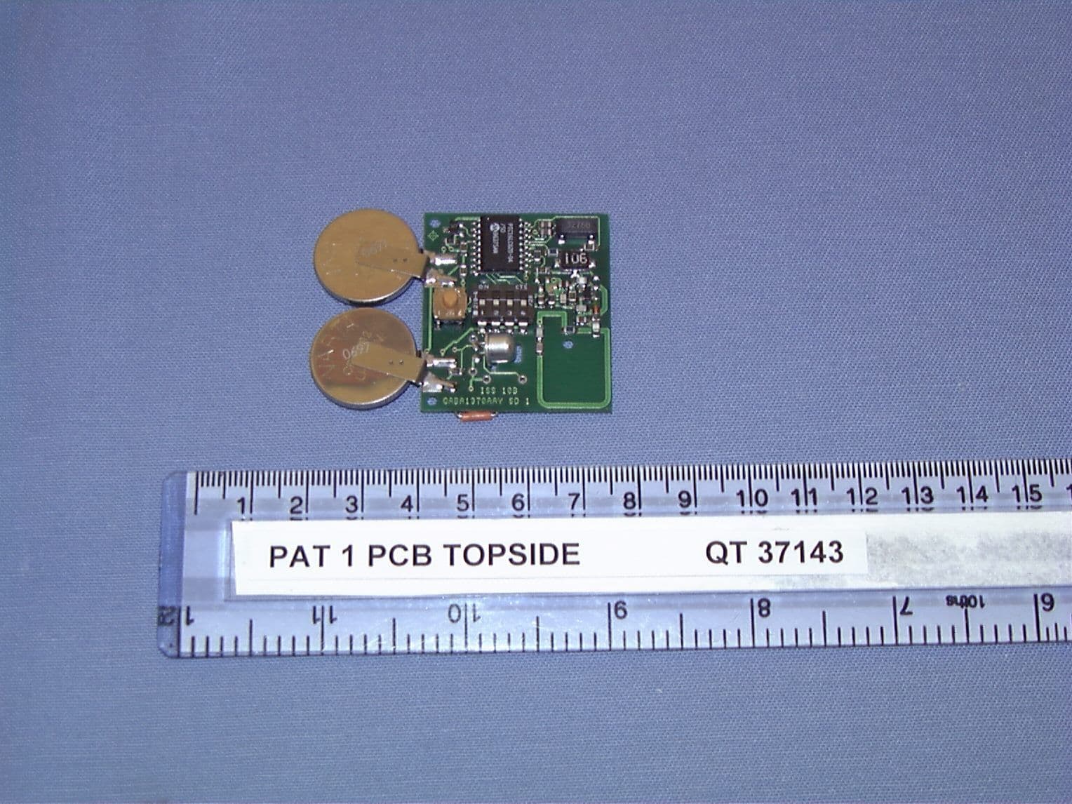
Click to zoom
Application Details
- Equipment Class
- DSC - Part 15 Security/Remote Control Transmitter
- Date of Grant
- Sep 27, 1999
- Application Purpose
- Original Equipment
- Date of Application
- Aug 17, 1998
- Equipment Note
- Theft Deterrent Transmitter
- Frequency Range
- 418.00000000 - 418.00000000
- Company
- Basys Technology Ltd
- Country
- United Kingdom
Documents & Files
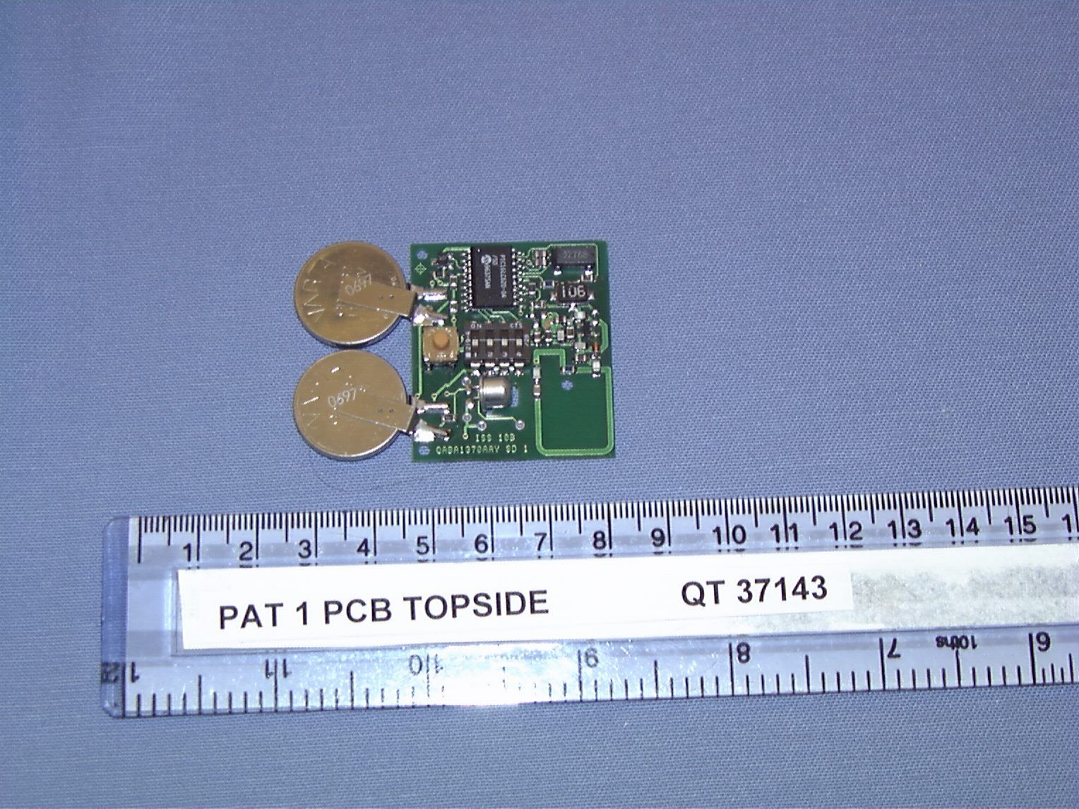
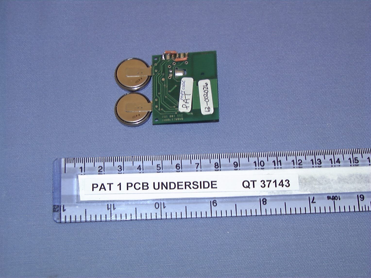
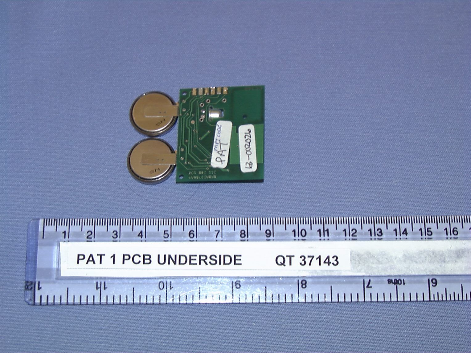
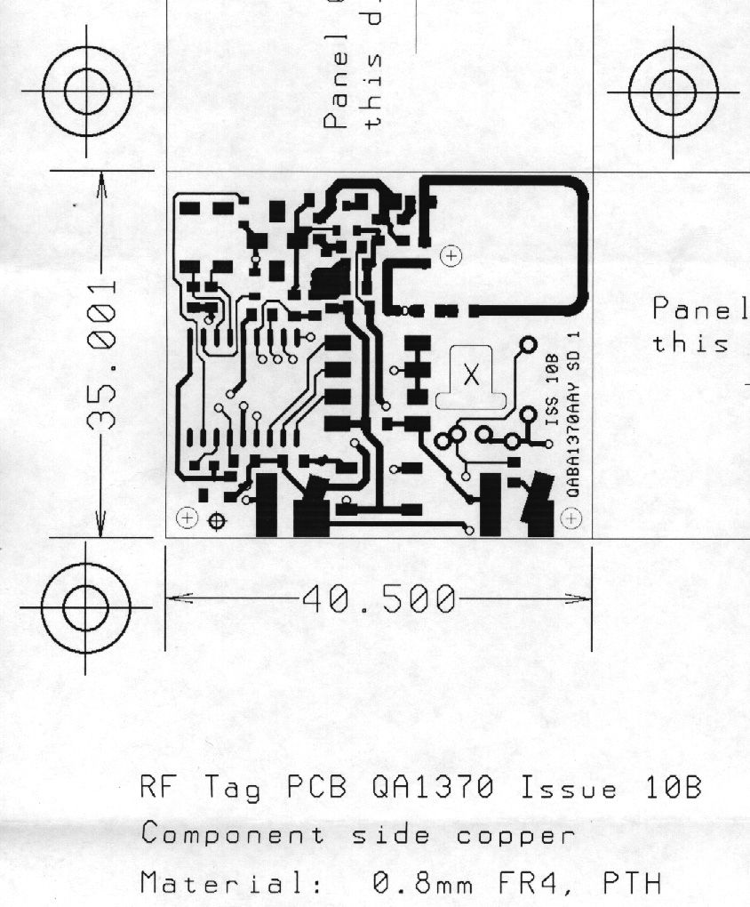
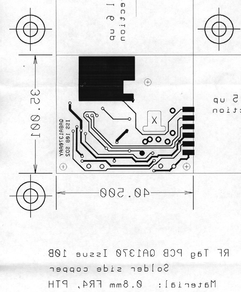
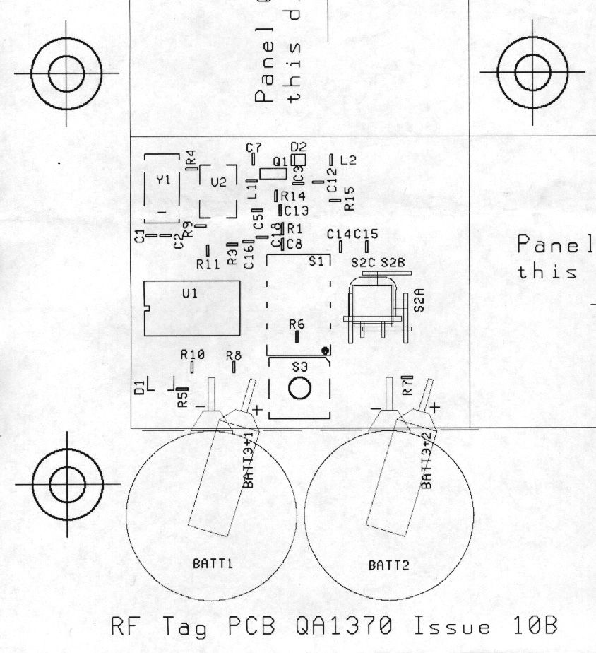
Document Text
Text extracted from the exhibit documents filed with the FCC. Open a document above to read the original.
Users Manual
ParSec Reader Installation Manual - Issue:2 - January 1998 - Page 1 ParSec READER INSTALLATION MANUAL Part No: IM016 Issue 2 January 1998 Newmark Technology Ltd 21-23, Ormside Way Redhill Surrey RH1 2NT United Kingdom Tel:+44(0) 1737 788800 Fax:+44(0) 1737 779535 Web site: www.newmarkworld.com Document No: A/IM 230 800 Prepared by: Alan Francis & Jon Hart ParSec Reader Installation Manual - Issue:2 - January 1998 - Page 2 ParSec READER INSTALLATION MANUAL C ONTENTS 1Caution - Static Precautions 2General Installation Notes 2.1Reader Design 2.2Siting the reader 2.3 Power Supply Requirements 2.4Communications Interfaces 2.4.1 RS-232 Data Port 2.4.2 Wiegand Data Port 2.5 External PIR Operation 3Installing the reader 3.1Fixing the Reader Enclosure 3.2Installing the Backplane Pcb 3.3Installing the Logic Pcb 4Commissioning the Reader 4.1Default Switch Settings 4.2Adjusting the read Range 4.2.1 Range Adjustment Procedure 4.3Setting the Reader Identity 4.3.1 Reader Number Programming 4.3.2 Sub-system Code Programming 4.4Setting the Indicators & Alarm Functions 4.4.1 Indicator LED Programming 4.4.2 Internal Sounder Programming 4.4.3 Alarm Relay Timer Programming 4.5PIR Operation 4.5.1 The Internal PIR 4.5.2 Using an External PIR 4.6Setting up the Communications Interfaces 4.6.1 Baud Rate Programming for RS-232 Data Comms. 4.6.2 Adjusting Static Tag Sensitivity 5Troubleshooting 5.1Reader Reset 5.2Tags not read 6Service & Repair 7Change Record ParSec Reader Installation Manual - Issue:2 - January 1998 - Page 3 1. CAUTION - S TATIC P RECAUTIONS Some devices used in the ParSec reader are static sensitive. Anti-static precautions must be taken when handling the printed circuit boards. Static discharge will permanently damage the boards. 2.G ENERAL I NSTALLATION N OTES 2.1.Reader Design The reader is mounted in a 2-part enclosure for surface mounting. The rear casing has 2 keyholes and 1 slotted hole for the 3 fixing screws and a variety of knock-out positions for ease of cable entry. The reader contains two PCB’s for ease of installation and maintenance. The rear B ACKPLANE P CB comprises two cable termination blocks, the power supply regulator and alarm relay, and two connectors to the front L OGIC P CB . The Backplane PCB will normally remain permanently mounted after the reader case has been sited and the cables installed. The L OGIC P CB contains the radio receiver, the microprocessor and communications circuitry, and the K EY PIC personality module. All reader adjustment and configuration is performed via the logic PCB, which is mounted onto the Backplane PCB via two push-fit connectors. This method of construction enables replacement of the logic PCB for maintenance purposes and also makes it possible for the physical mounting and cabling of the reader enclosure and Backplane to be carried out prior to system configuration and commissioning. The reader front cover is protected from unauthorised entry by a recessed security screw. For this to be removed for installation, you will need a Newmark security driver (Part no SS0001 or RS part 541-983). Any attempt to remove the front cover will operate an anti- tamper switch which may be set to trigger a local or remote alarm (e.g. sounder/lamp) and, if the reader is connected to a computer-based system, to raise an alarm at the system control console. There are 2 types of reader. The model PSR-232-1 has an RS232 port and is normally used with TransAsset or other third party asset management software. The model PSR-W26-1 has a 26-bit industry standard wiegand card type data output and is normally used with access control systems. It is possible to convert from 1 model to another by simply changing the socketed KeyPIC. All the tags transmit at 418 MHz using a power level which in the UK is MPT 1340 licence exempt by the DTI. For those countries where 418 MHz is not acceptable, tags and readers operating at 433 MHz will become available in mid 1998. All units are CE marked and comply with European EMC directives. However, to maintain this compliance, it is essential that you follow the installation procedures in this manual and in particular use grounded screened cables where specified. ParSec Reader Installation Manual - Issue:2 - January 1998 - Page 4 2.2.Siting the reader The physical location chosen to site each reader will depend principally upon (1)The area of coverage required for Static Asset Tags (PS-SAT1-1’s). (2)The exit/entry points to be protected or monitored with Portable Asset Tags (PS-PAT1-1’s) and Personnel Tags (PS-PET1-1’s). For 'portal monitoring' with PS-PAT1-1’s and PS-PET1-1’s, the reader should be sited in line with the centre of the doorway and midway between the top of the door and the ceiling. (This is not critical and, in some cases, it may be appropriate to site the reader in a higher position to deter vandalism.) Where the system is used solely for monitoring unauthorised movement of items protected by PS-SAT1-1’s, the reader should be mounted 0.5m below the ceiling and in the centre of a convenient wall in the location, to optimise the polar pattern of the receiving antenna. Up to nine of the RS232 type readers can be chained to provide extended coverage of a wide or irregularly shaped area. (For details of reader addressing, see section 4.3.) Notes "DIFFICULT" LOCATIONS (1)The reader enclosure is partially screened to reduce the sensitivity to tags from the rear. Where REAR DETECTION is a problem, a new type of uni-directional antenna is being developed. Contact your supplier or Newmark for more information. (2)The reader is supplied with aluminium shield which can be fitted to the reader after installation to reduce its sensitivity to tags being read through the ceiling from the floor above. If this is required, peel off the self-adhesive backing strip and place it inside the top of the reader enclosure. Note that it covers the 2 upper fixing screw holes, so you will need to use countersunk head fixing screws. (2)The pres…
Text truncated - open the document above for the full version.
Users Manual
© BASYS TECHNOLOGY LIMITED 1998 41157.DOC Page 1 of 11 The copyright in this document is vested in Basys Technology Limited. This document is issued only for the purpose for which it is supplied. And on the express terms that it is to be treated as commercially confidential and that it may not be reproduced in whole or in part, or used or disclosed to others for any purpose except as authorised in writing by this company. REFERENCE:Project number 362020 Document number 00-8006 TITLE: FCC TAG Set Description of Operation Intelitag Asset and Personnel RF Tagging System ISSUE: b DATE:7 th March 1998 AUTHOR:Stephen Grant Electronic Design Engineer APPROVED BY: POSITION: Mark Mitchelmore Engineering Manager AUTHORISED BY: POSITION: Richard Papanicolaou Quality Director © BASYS TECHNOLOGY LIMITED 1998 41157.DOC Page 2 of 11 The copyright in this document is vested in Basys Technology Limited. This document is issued only for the purpose for which it is supplied. And on the express terms that it is to be treated as commercially confidential and that it may not be reproduced in whole or in part, or used or disclosed to others for any purpose except as authorised in writing by this company. Revision History DateDetails of changeIss. /Change No. 7/4/99Draft a 17/5/99V. minor textual changes and a change to RAT transmission timing. Renamed R.A.T. to RAT. Addition of new paragraph 7 detailing FCC Identification Draft b © BASYS TECHNOLOGY LIMITED 1998 41157.DOC Page 3 of 11 The copyright in this document is vested in Basys Technology Limited. This document is issued only for the purpose for which it is supplied. And on the express terms that it is to be treated as commercially confidential and that it may not be reproduced in whole or in part, or used or disclosed to others for any purpose except as authorised in writing by this company. 1 Contents 1CONTENTS ......................................................................................................................................... 3 2INTRODUCTION ............................................................................................................................... 4 3SYSTEM DESCRIPTION .................................................................................................................. 5 4REFERENCE DOCUMENTATION................................................................................................. 6 4.1R EFERENCE D OCUMENTATION .......................................................................................................... 6 5TRANSMISSION REQUIREMENTS .............................................................................................. 6 5.1FCC RULES ....................................................................................................................................... 6 6TAG TRANSMISSION TIMING AND OPERATING FIELD STRENGTH ............................... 7 6.1PAT TAG ......................................................................................................................................... 7 6.2SAT TAG ......................................................................................................................................... 8 6.3RAT TAG ......................................................................................................................................... 9 7FCC IDENTIFICATION.................................................................................................................. 11 7.1T AGS ............................................................................................................................................... 11 7.2R EADER ........................................................................................................................................... 11 8FCC MODIFICATION DISCLAIMER AND OTHER STATEMENTS..................................... 11 © BASYS TECHNOLOGY LIMITED 1998 41157.DOC Page 4 of 11 The copyright in this document is vested in Basys Technology Limited. This document is issued only for the purpose for which it is supplied. And on the express terms that it is to be treated as commercially confidential and that it may not be reproduced in whole or in part, or used or disclosed to others for any purpose except as authorised in writing by this company. 2 Introduction This document describes the transmission timing and power levels of the Intelitag Tag transmitters for conformance to FCC Part 15 Subpart C for intentional transmitters. © BASYS TECHNOLOGY LIMITED 1998 41157.DOC Page 5 of 11 The copyright in this document is vested in Basys Technology Limited. This document is issued only for the purpose for which it is supplied. And on the express terms that it is to be treated as commercially confidential and that it may not be reproduced in whole or in part, or used or disclosed to others for any purpose except as authorised in writing by this company. 3 System Description The Intelitag ™ electronic tagging system, also distributed under the ParSec trade name, is a radio based short to long range tagging system for the protection and monitoring of assets. The system operates at a nominal frequency of 418MHz as a Low-Power, Non-Licensed Transmitter in accordance with FCC Part 15 Subpart C for intentional Radiators (TAGs) and Subpart B for unintentional radiators (Reader). The system is also type approved to MPT- 1340 licence exempt frequency band by the UK Radiocommunications Agency. Approval number 13422 refers. The basic system comprises a range of tags - compact radio frequency transmitters which communicate with a universal reader . The reader interprets the data packet received from a tag transmitting within its field of reception and, in turn, passes this data on to a controller or computer. Using a combination of two power levels and differing data patterns, the universal reader is able to distinguish between ‘long range’ and ‘short range’ Intelitags. Long range tags a…
Text truncated - open the document above for the full version.
Users Manual
ParSec Reader Installation Manual - Issue:3 - December 1998 - Page 1 ParSec READER INSTALLATION MANUAL Part No: IM016 DRAFT Issue 4 March 1999 Newmark Technology Ltd 21-23, Ormside Way Redhill Surrey RH1 2NT United Kingdom Tel:+44(0) 1737 788800 Fax:+44(0) 1737 779535 Web site: www.newmarkworld.com Document No: A/IM 230 800 Prepared by: Alan Francis & ParSec Reader Installation Manual - Issue:3 - December 1998 - Page 2 Jon Hart FCC Compliance Statement For United States Users These devices comply with part 15 of the FCC CFR 47 rules. Operation is subject to the following two conditions: (1)These devices may not cause harmful interference, and (2) these devices must accept interference received, including interference that may cause undesired operation. The user is cautioned that modifications or changes to an intentional or unintentional radiator not expressly approved by the party responsible for compliance could void the user's authority to operate the equipment. The tags are powered are by standard Lithium coin cells and as such the following warning shall be noted: CAUTION Danger of explosion if batteries are incorrectly replaced. Replace only with the same or equivalent type recommended by the manufacturer. Dispose of used batteries according to the manufacturers instructions in this manual. ParSec Reader Installation Manual - Issue:3 - December 1998 - Page 3 ParSec READER INSTALLATION MANUAL C ONTENTS 1Caution - Static Precautions 2General Installation Notes 2.1Reader Design 2.2Siting the reader 2.3 Power Supply Requirements 2.4Communications Interfaces 2.4.1 RS-232 Data Port 2.4.2 Wiegand Data Port 2.5 External PIR Operation 3Installing the reader 3.1Fixing the Reader Enclosure 3.2Installing the Backplane PCB 3.3Installing the Logic PCB 4Commissioning the Reader 4.1Default Switch Settings 4.2Adjusting the read Range 4.2.1Range Adjustment Procedure 4.3Setting the Reader Identity 4.3.1Reader Number Programming 4.3.2Sub-system Code Programming 4.4Setting the Indicators & Alarm Functions 4.4.1Indicator LED Programming 4.4.2Internal Sounder Programming 4.4.3Alarm Relay Timer Programming 4.5PIR Operation 4.5.1The Internal PIR 4.5.2Using an External PIR 4.6Setting up the Communications Interfaces 4.6.1Baud Rate Programming for RS-232 Data Comms. 4.6.2Adjusting Static Tag Sensitivity 5 Personnel Tag Operation 6 Tag Transmission Timing 7 Troubleshooting 7.1Reader Reset 7.2Tags not read 8Service & Repair 9Change Record ParSec Reader Installation Manual - Issue:3 - December 1998 - Page 4 1. CAUTION - S TATIC P RECAUTIONS Some devices used in the ParSec reader are static sensitive. Anti-static precautions must be taken when handling the printed circuit boards. Static discharge will permanently damage the boards. 2.G ENERAL I NSTALLATION N OTES 2.1.Reader Design The reader is mounted in a 2-part enclosure for surface mounting. The rear casing has 2 keyholes and 1 slotted hole for the 3 fixing screws and a 25mm diameter knock-out hole in the rear face for cable entry. The reader contains two PCB’s for ease of installation and maintenance. The rear B ACKPLANE P CB comprises two cable termination blocks, the power supply regulator, 1A fuse, alarm relay, and two connectors to the front L OGIC P CB . The Backplane PCB will normally remain permanently mounted after the reader case has been sited and the cables installed. The L OGIC P CB contains the radio receiver, the microprocessor and communications circuitry, and the K EY PIC personality module. All reader adjustment and configuration is performed via the logic PCB, which is mounted onto the Backplane PCB via two push-fit connectors. This method of construction enables replacement of the logic PCB for maintenance purposes and also makes it possible for the physical mounting and cabling of the reader enclosure and Backplane to be carried out prior to system configuration and commissioning. The reader front cover may be fitted with a recessed security screw. It is normally supplied with a standard M3 screw fitted but alternative M3 “Torx” and Newmark type screws are also provided. For these to be used for installation, you will need a “Torx” type TX10 screwdriver (e.g. RS: 662-585) or a Newmark security driver (Part no SS0001 or RS part 541-983). Any attempt to remove the front cover will operate the internal anti-tamper switch which may be set to trigger a local or a remote alarm. There are 2 types of reader. The model PSR-232-1 has an RS232 port and is normally used with TransAsset or other third party asset management software. The model PSR-W26-1 has a 26-bit industry standard wiegand card type data output and is normally used with access control systems. It is possible to convert from 1 model to another by simply changing the socketed KeyPIC. All the tags transmit at 418 MHz using a power level which in the UK is MPT 1340 licence exempt by the DTI. Tags for sale in the USA meet FCC part 15 rules. For those countries where 418 MHz is not acceptable, for example mainland Europe tags and readers operating at a different frequency may become available in 1999. All units are CE marked and comply with European EMC directives. However, to maintain this compliance, it is essential that you follow the installation procedures in this manual and in particular use grounded screened cables where specified. ParSec Reader Installation Manual - Issue:3 - December 1998 - Page 5 2.2.Siting the reader The physical location chosen to site each reader will depend principally upon (1)The area of coverage required for Static Asset Tags (PS-SAT1-1’s). (2)The exit/entry points to be protected or monitored with Portable Asset Tags (PS-PAT1-1’s) and Personnel Tags (PS-PET1-1’s). For 'portal monitoring' with PS-PAT1-1’s and PS-PET1-1’s, the reader should be sited in line with the centre of the doorway and midway between the top of the door and the ceiling. (This is not critical and, in some cases, it may be appropriate to site the reader in a higher position to deter va…
Text truncated - open the document above for the full version.
Cover Letter(s)
Basys Technology Ltd. Mumby Road Gosport Hampshire England PO12 1AF Tel: (01705) 584222 Facsimilie: (01705) 529598 Registered office: Royex House Aldermanbury Square London EC2V 7HRRegistered in England No. 1423812 David Maina Radio Frequency Investigation Ltd Ewhurst Park Ramsdell Basingstoke Hampshire RG26 5RG 7 September, 1998 Reference: RFI.test.authorisation Dear David, This letter, gives RFI ltd authorisation to perform all test work and applications necessary for Basys Technology’s 418MHz Electronic Tagging product in accordance with FCC Part 15 Subpart C for intentional Radiators (TAGs), and Subpart B for unintentional radiators (Reader). Yours sincerely Stephen Grant
ID Label/Location Info
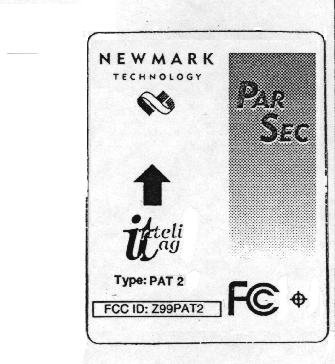
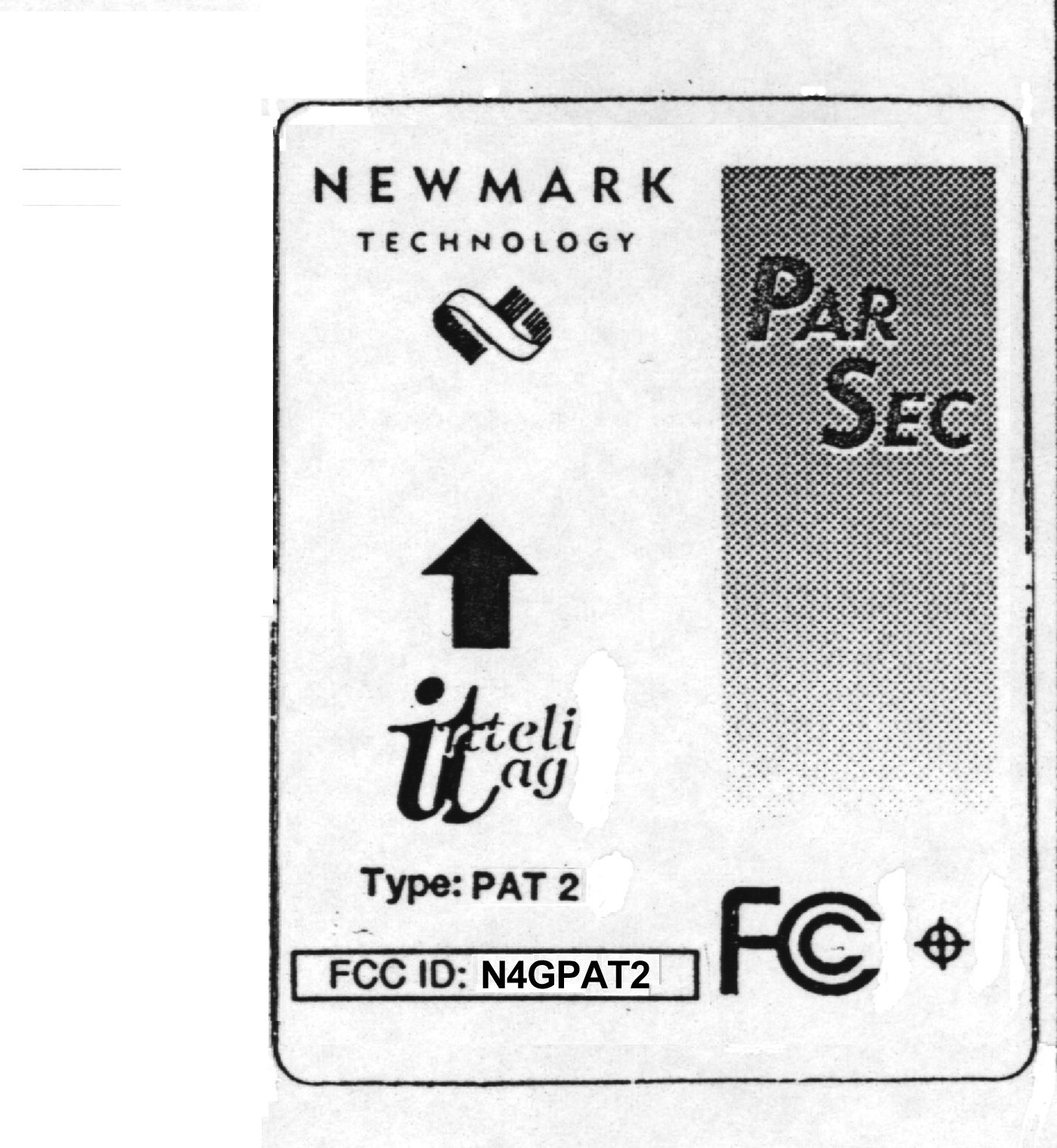
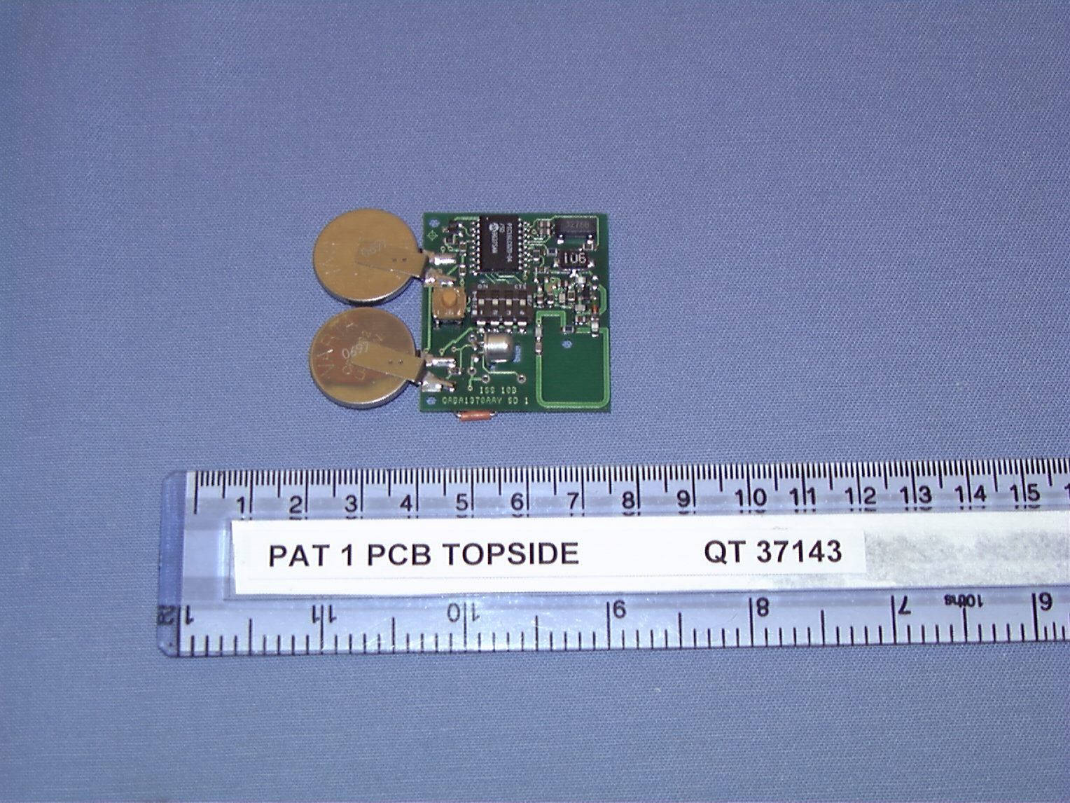
Page 1 of 4 Application of Tagging System for FCC ApprovalIdentification of imagesPage 2 TAG PCB Electrical Schematic Page 3 PAT and SAT Identification Labels Page 4 RAT Identification Label Page 2 of 4 QA1370 10b Intelitag TAG - MPT 1340 A 11 Wednesday , February 17, 1999 Tit leSize Document Number Rev Date: Sheet of S1SW DIP-4 1234 8765 D1 DA204K BATT1BATTER Y C8100n Y132.768KHZ Q1BFS17A R710M S2 SHOCK SWITCH BATT2BATTER Y BATT3P1 BATT3P2 TP1 R1022K R5100K C122pC222p R810M TP2 BATT3 EC1 EDGE FINGERS 123456 R1410R L147n C33.3pC136.8p L247n C1247p R90RR4220R D2 BAT46 R11100K C18not f itted C16not f itted C1556p C143.9p R150R C7 not f itted U1PIC16C620-04/SO 1718 12 678910111213 34 1615 RA0RA1RA2RA3 RB0RB1RB2RB3RB4RB5RB6RB7 RA4MC LR OSC1OSC2 R1100R S3 ANTI-TAMPER R60R C5100n U2R02103A 3 1 IN OUT R3120K LBDRVRESET TAMPERPROGCLA1 TXLO LA2 VB- TXD ATALA0SWDRV VBATT TXH I ANTENNA BUILD VARIANTS (Y=Fitte d) PETPA TSA TRA T R4 R6 R7 R8 R9 S2 S3 BA TT1/ 2 S1 220R220R220R1.2K Y YYYYYY YYYYYYY YYYYYYY Y FOR FCC VARIANTS, R4 ON ALL TAGS IS 910R Page 3 of 4 Page 4 of 4
ID Label/Location Info
Basys Technology Ltd. Mumby Road Gosport Hampshire England PO12 1AF Tel: (01705) 584222 Facsimilie: (01705) 529598 Registered office: Royex House Aldermanbury Square London EC2V 7HRRegistered in England No. 1423812 Mr Nick Cobb Radio Frequency Investigation Limited Ewhurst Park Ramsdell Basingstoke Hampshire RG26 5RQ 20 July, 1999 Reference: inteli058 Dear Nick, Recently I have sent to you a SAT, PAT and RAT for photographing for the inclusion of the photographs in our FCC application. As you have noticed the labels on these devices do not match the requirements of the FCC. The reason for this is because we have not yet produced tags for sale in the US and hence labels. Therefore, inserted into this document are the electronic versions of the labels for the FCC variants of our TAG transmitters. Please note that the images appended are black and white when in fact the colours will be identical to those shown on the actual tags. All extra text though will be in black. Yours sincerely Stephen Grant Basys Technology Ltd. Mumby Road Gosport Hampshire England PO12 1AF Tel: (01705) 584222 Facsimilie: (01705) 529598 Registered office: Royex House Aldermanbury Square London EC2V 7HRRegistered in England No. 1423812 Basys Technology Ltd. Mumby Road Gosport Hampshire England PO12 1AF Tel: (01705) 584222 Facsimilie: (01705) 529598 Registered office: Royex House Aldermanbury Square London EC2V 7HRRegistered in England No. 1423812
Operational Description
COMMERCIAL-IN-CONFIDENCE Intelitag Technical Product Description (FCC) - Issue 1, 25 June 1998 Page 1 of 3 Basys Technology Ltd. Mumby Road Gosport Hampshire England PO12 1AF Intelitag Technical Product Description (FCC) 1 - General The Intelitag ™ electronic tagging system, also distributed under the ParSec trade name, is a radio based short to long range tagging system for the protection and monitoring of assets and the management of personnel movement. The system operates at a nominal frequency of 418MHz as a Low-Power, Non-Licensed Transmitter in accordance with FCC Part 15 Subpart C for intentional Radiators (TAGs) and Subpart B for unintentional radiators (Reader). The system is also type approved to MPT-1340 licence exempt frequency band by the UK Radiocommunications Agency. Approval number 13422 refers. The basic system comprises a range of tags - compact radio frequency transmitters that communicates with a universal reader . The reader interprets the data received from a tag transmitting within its field of reception and, in turn, passes this data on to a controller or computer. Using a combination of two power levels and differing data patterns, the universal reader is able to distinguish between ‘long range’ and ‘short range’ Intelitags. Long range tags are read at a nominal distance of up to 75m in free space, depending on the characteristics of the ambient RF environment, regardless of their proximity to the reader. The reader only detects short-range tags when they enter its short-range zone, which is adjustable from a few cm to 25m in free space. It is the combination of short and long-range detection within a single reader, which, in conjunction with the properties of the different tag types described below, which gives the Intelitag system its unique performance characteristics. Every tag has a unique identity, which it transmits in conjunction with additional data relating to its operational status. Thus an asset or individual equipped with a tag can be uniquely identified by the system. The Intelitag system has been designed primarily for security applications although its use can also be extended to a wide range of asset tracking and management tasks. A regular ‘reporting’ transmission from asset Intelitags provides both a security confidence check and an additional asset management (inventory) facility. Asset Intelitags incorporate anti-tamper switches, which are detected at long range. COMMERCIAL-IN-CONFIDENCE Intelitag Technical Product Description (FCC) - Issue 1, 25 June 1998 Page 2 of 3 Basys Technology Ltd. Mumby Road Gosport Hampshire England PO12 1AF 2 - Tag Types The Static Intelitag (SAT) has been designed primarily to protect equipment such as computers and their internal components, an all other types of static office equipment. However, the SAT is highly versatile and can be used to protect any static article including hospital and laboratory equipment, works of art and any item of significant value. The SAT incorporates a movement sensor and can be detected at a range of up to 75m in clear space. The Portable Intelitag (PAT) has been designed to allow the movement of mobile assets within a controlled area or building, whilst denying or monitoring the removal from, and re- entry of the assets into the area. The PAT is normally detected when it enters the short range zone of a universal reader; however its other transmissions, including tamper, will be detected by a reader at long range. 3 - Tag Operating Modes Intelitags operate in several predetermined transmission modes of high and low power. High power transmission is approximately -28 dBm and low power is -33 dBm. The transmitted data packet duration is constant for all tags at 22.75 milliseconds (all packets are identical in length). The power of the transmission and transmission repetition rates are determined by the tag type and its operating mode. The various operating modes for each tag are described below. Static Intelitag (SAT) 1. Tamper mode 2. Wake mode 3. Routine report mode 4. Low battery mode Portable Intelitag (PAT) 1. Tamper mode 2. Wake mode 3. Routine reporting mode 4. Low battery mode Range Adjustment Intelitag (RAT) 1. See 2. Find 3. Plus range 4. Minus range COMMERCIAL-IN-CONFIDENCE Intelitag Technical Product Description (FCC) - Issue 1, 25 June 1998 Page 3 of 3 Basys Technology Ltd. Mumby Road Gosport Hampshire England PO12 1AF 4 - Operating Mode Descriptions T AMPER M ODE (manually triggered transmission) Tamper mode is triggered by the forcible removal of a SAT or PAT tag from the item to which it is attached. A micro switch is open circuited by the removal of the tag. The tag software continuously monitors the condition of the switch; when it changes to the ON state, the tag transmits continuously in high power every 0.6 seconds. The transmission is turned off by returning the switch to its OFF state. W AKE M ODE (manually triggered transmission) When a PAT tag is disturbed, the change of state of its shock sensor causes the software to transmit packets every 0.6 seconds in low power. The duration of the transmission is 3.2 seconds. If, during the 3.2 second period, the shock sensor is disturbed again the transmission restarts. When a SAT tag is disturbed, the change of state of its shock sensor causes the software to transmit packets every 1.2 seconds in high power. The duration of the transmission is 3.6 seconds (3 cycles). If, during the 3.6 second period, the shock sensor is disturbed again the timed transmission restarts. R OUTINE R EPORTING (automatic transmission) The PAT routine report comprises 5 packet transmissions at 0.6 second intervals in high power, repeated hourly. The hourly timer is reset if interrupted by movement of the PAT. The SAT routine report comprises 5 packet transmissions at 1.2 second intervals in high power, repeated hourly. L OW B ATTERY (automatic transmission) The setting of a status flag during any report transmission, including routine repor…
Text truncated - open the document above for the full version.
Operational Description
COMMERCIAL-IN-CONFIDENCE Intelitag Technical Product Description (FCC) - Issue 3, 4 th Septem ber 1998 Page 1 of 5 Basys Technology Ltd. M um by Road Gosport Ham pshire England PO12 1AF Intelitag Technical Product Description (FCC) 1 - General The Intelitag ™ electronic tagging system, also distributed under the ParSec trade name, is a radio based short to long range tagging system for the protection and monitoring of assets and the management of personnel movement. The system operates at a nominal frequency of 418MHz as a Low-Power, Non-Licensed Transmitter in accordance with FCC Part 15 Subpart C for intentional Radiators (TAGs) and Subpart B for unintentional radiators (Reader). The system is also type approved to MPT-1340 licence exempt frequency band by the UK Radiocommunications Agency. Approval number 13422 refers. The basic system comprises a range of tags - compact radio frequency transmitters which communicate with a universal reader . The reader interprets the data received from a tag transmitting within its field of reception and, in turn, passes this data on to a controller or computer. Using a combination of two power levels and differing data patterns, the universal reader is able to distinguish between ‘long range’ and ‘short range’ Intelitags. Long range tags are read at a nominal distance of up to 75m in free space, depending on the characteristics of the ambient RF environment, regardless of their proximity to the reader. Short range tags are only detected by the reader when they enter its short range zone, which is adjustable from a few cm to 25m in free space. It is the combination of short and long range detection within a single reader which, in conjunction with the properties of the different tag types described below, which gives the Intelitag system its unique performance characteristics. Every tag has a unique identity which it transmits in conjunction with additional data relating to its operational status. Thus an asset or individual equipped with a tag can be uniquely identified by the system. The Intelitag system has been designed primarily for security applications although its use can also be extended to a wide range of asset tracking and management tasks. A regular ‘reporting’ transmission from asset Intelitags provides both a security confidence check and an additional asset management (inventory) facility. Asset Intelitags incorporate anti-tamper switches which are detected at long range. COMMERCIAL-IN-CONFIDENCE Intelitag Technical Product Description (FCC) - Issue 3, 4 th Septem ber 1998 Page 2 of 5 Basys Technology Ltd. M um by Road Gosport Ham pshire England PO12 1AF 2 - Tag Types The Static Intelitag (SAT) has been designed primarily to protect equipment such as computers and their internal components, and all ot…
Text truncated - open the document above for the full version.
Contact Information
Applicant
Stephen Grant(Electronic Design Engineer)
Technical Contact
Radio Frequency Investigation LtdNick Cobb
[email protected]+44 1256 855472
Ewhurst Park, Ramsdell · Basingstoke · United Kingdom
Non-Technical Contact
Radio Frequency Investigation LtdDavid Maina
[email protected]+44 1256 855472
Test Firm
RFI Global Services Ltd.Allan Hume
Technical Specifications
| # | Rule Parts | Frequency Range | Power Output |
|---|---|---|---|
| 1 | 15C | 418 MHz - 418 MHz | - |
Other Applications from Basys Technology Ltd
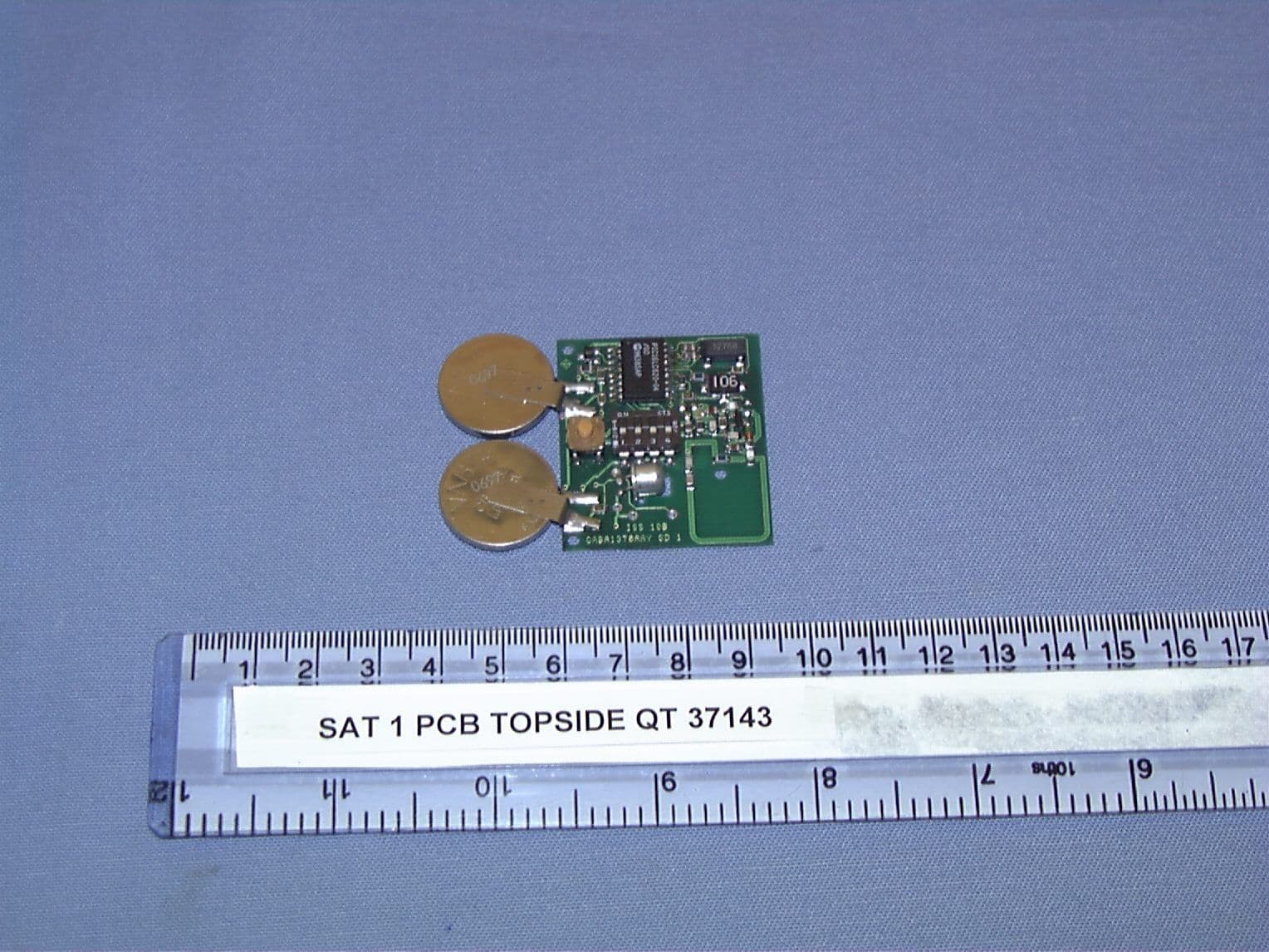
N4GSAT2
Sep 27, 1999Theft Deterrent Transmitter
Equipment Class
DSC - Part 15 Security/Remote Control TransmitterN4GREADER
Oct 28, 1998READER
Equipment Class
CYY - Communications Receiver used w/Pt 15 Transmitter