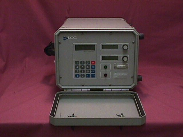
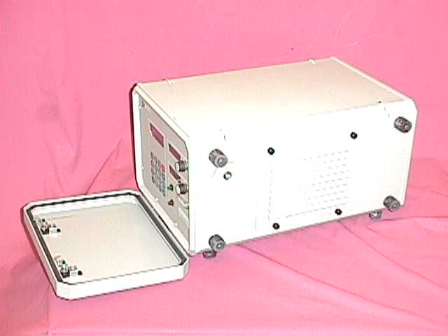
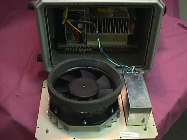
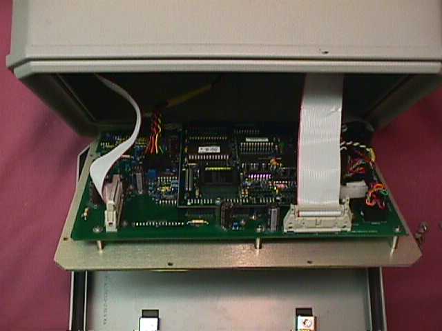
N4P-41-A00818Test Transmitter
Ericsson NetQual Inc.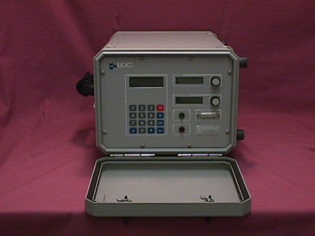
Click to zoom
Application Details
- Equipment Class
- TNB - Licensed Non-Broadcast Station Transmitter
- Date of Grant
- Nov 09, 1998
- Application Purpose
- Original Equipment
- Date of Application
- Sep 08, 1998
- Equipment Note
- Test Transmitter
- Frequency Range
- 1930.20000000 - 1989.80000000
- Company
- Ericsson NetQual Inc.
- Country
- United States
Documents & Files

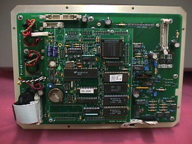
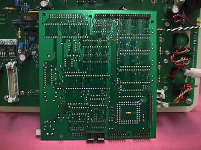
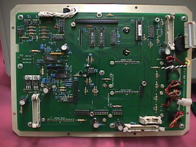
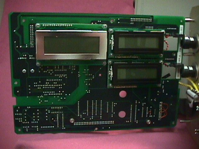
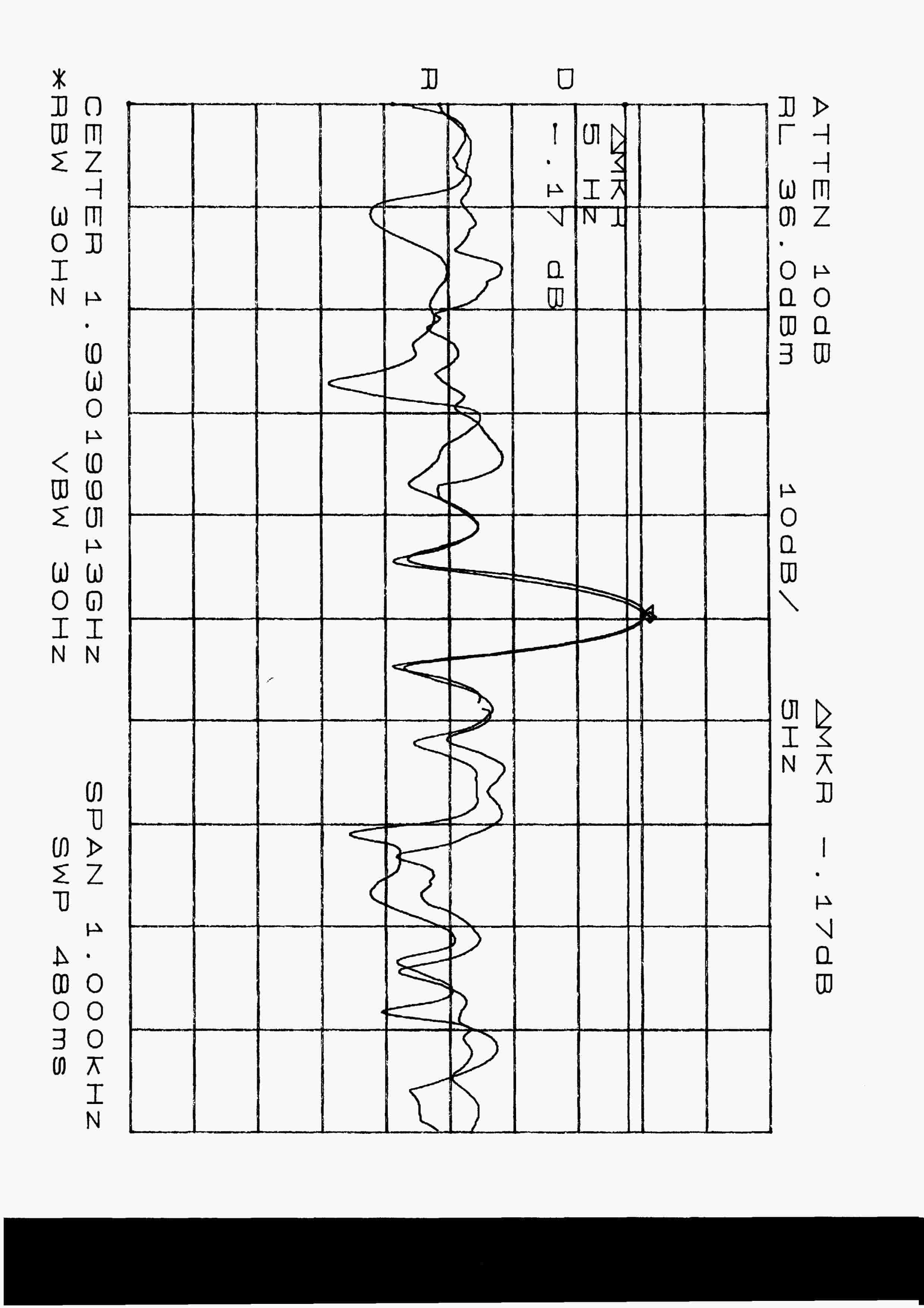
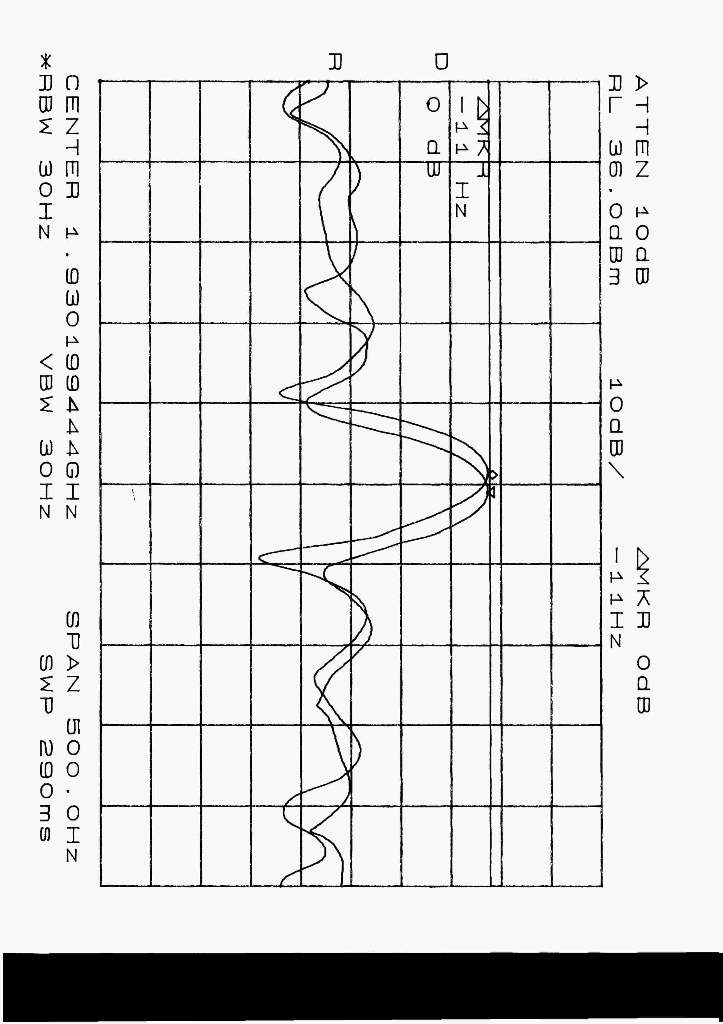
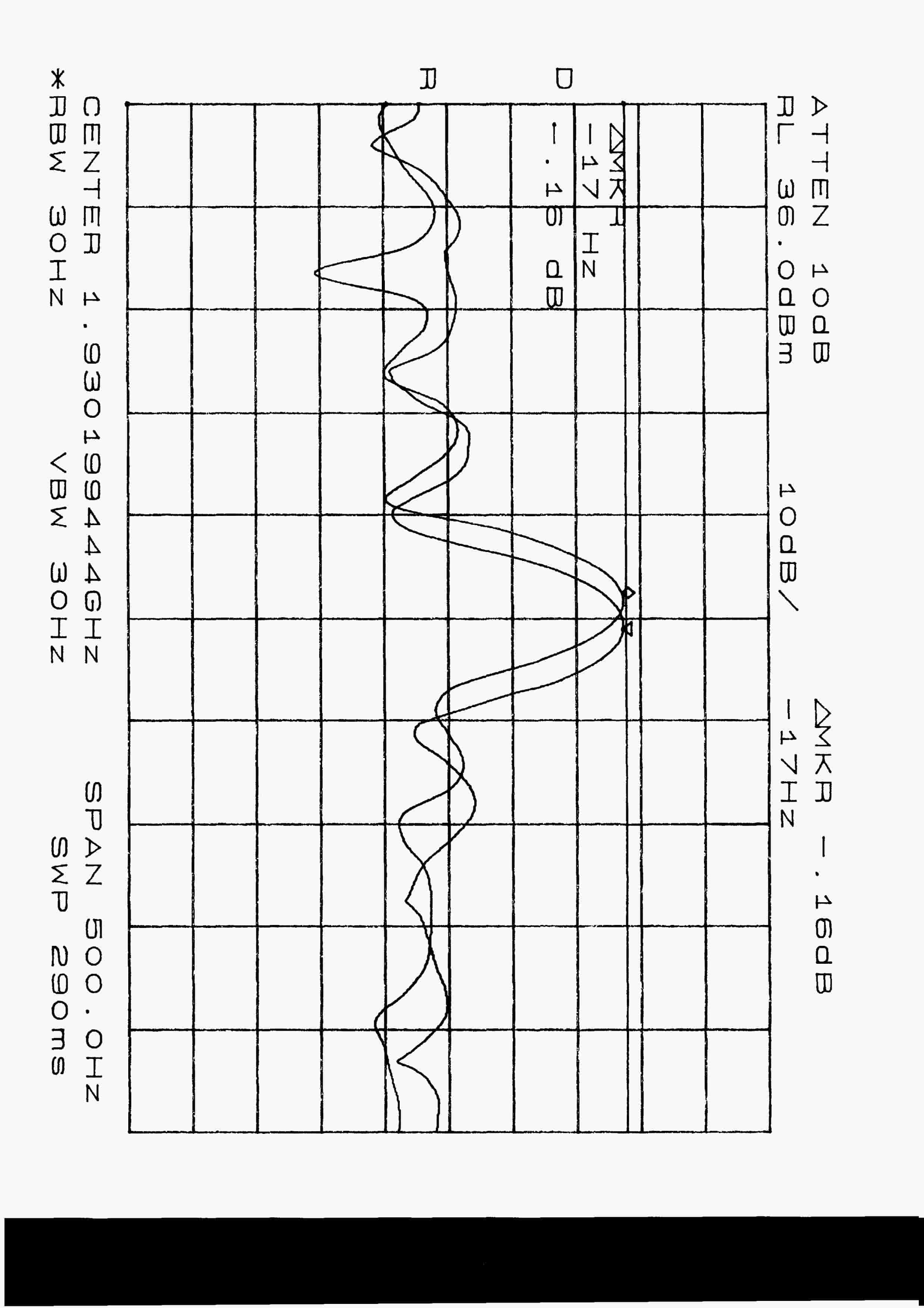
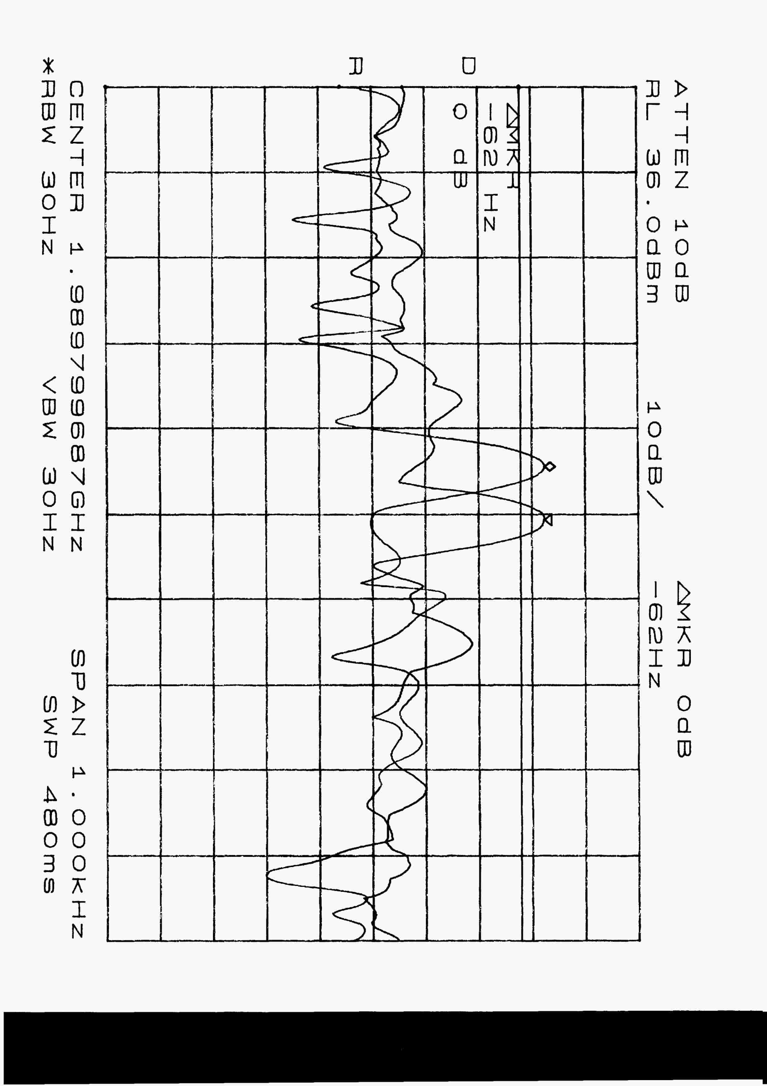
Document Text
Text extracted from the exhibit documents filed with the FCC. Open a document above to read the original.
Users Manual
Users Manual LCC International, Inc. SpectraWave 1900 Users Manual LCC p/n 41-A00818-1 Copyright © 1998 LCC International, Inc. All Rights Reserved 7925 Jones Branch Drive, McLean, Virginia 22102 Phone: (703) 873-2000 FAX: (703) 873-2100 Customer Support: 1-800-522-9670 8:00 AM - 8:00 PM Eastern Standard Time (EST) e-mail: [email protected] If you have any questions regarding this manual, contact Hardware Customer Support at the phone numbers above, or send an e-mail to: [email protected]. You also can contact us at our website at www.lcc.com. Software License Agreement The software described in this document has been provided under a separate Software License Agreement. The software in this document may be used and copied only in accordance with such Software License Agreement. Unauthorized use or copying of the software, this document or any related materials may result in civil liability and/or criminal prosecution. The information in this document is subject to change without notice and does not represent commitment on the part of LCC International, Inc. The software License Agreement sets forth the only warranties made by LCC International, Inc. with respect to the software. Such warranties are in lieu of, and LCC expressly dis- claims, any and all other warranties, express or implied, statutory or otherwise. LCC is a service mark of LCC International, Inc. SpectraWave 1900 is a trademark of LCC International, Inc. Contents 3 1 Introduction 1.1 About This Manual ............................................................................................ 1-1 1.2 What is in this Manual ....................................................................................... 1-2 1.3 Document Conventions...................................................................................... 1-2 1.4 Technical Support .............................................................................................. 1-3 2 SpectraWave 1900 Transmitter Basics 2.1 Basic Transmitter Configuration ....................................................................... 2-2 2.2 User Interface..................................................................................................... 2-3 2.2.1 Menu-Driven Screens Display .................................................................. 2-3 2.2.2 Numerical Screens (Power and Frequency).............................................. 2-6 2.2.3 Status Lights ............................................................................................. 2-6 2.2.4 Antenna Accessory Kit ............................................................................. 2-6 2.2.5 Transmitter Power Supply ........................................................................ 2-7 2.3 SpectraWave 1900 Convenience Features......................................................... 2-8 2.4 Preparing SpectraWave 1900 for Operation ...................................................... 2-9 2.4.1 Checking and Maintaining the Air Filter .................................................. 2-9 2.4.2 Setting Up the SpectraWave 1900 .......................................................... 2-10 2.4.3 Setting Test Parameters .......................................................................... 2-11 2.5 Preparing SpectraWave 1900 for Shipping ..................................................... 2-12 3 Quick Start 3.1 Powering Up SpectraWave 1900 ....................................................................... 3-2 3.2 Status Menu Screen ........................................................................................... 3-3 3.3 Setup Menu Screen ............................................................................................ 3-3 3.3.1 Protocol Screen ......................................................................................... 3-4 3.3.2 Frequency/Channel Screen ....................................................................... 3-5 3.3.3 Power Screen ............................................................................................ 3-6 3.3.4 Clock Setup Screen ................................................................................... 3-7 3.3.5 LCD Contrast Setup Screen ...................................................................... 3-8 3.3.6 Setup Menu-2 Screen ................................................................................ 3-9 3.3.6.1 Cable Loss (Lc) Screen ............................................................. 3-10 3.3.6.2 Antenna Gain (Ga) Screen ........................................................ 3-11 3.4 Diagnostics Menu Screen ................................................................................ 3-12 3.4.1 Error Log View/Log Screen ................................................................... 3-13 3.4.2 Power Amp Status Screen....................................................................... 3-15 3.4.3 Voltage Status Screen ............................................................................. 3-16 3.4.4 Synthesizer Status Screen ....................................................................... 3-17 Contents 4 3.4.5 Ambient Temperature Screen ................................................................. 3-18 3.4.6 Diagnostics Menu-2 Screen .................................................................... 3-19 3.5 Setting Up an PCS 1900 Protocol .................................................................... 3-20 4 Functional Screens 4.1 Using Setup Functions ....................................................................................... 4-3 4.1.1 Selecting Protocol ..................................................................................... 4-3 4.1.2 Selecting Frequency and Channel Number .............................................. 4-5 4.1.3 Selecting Power ........................................................................................ 4-6 4.1.4 Setting the Clock and Date ...........................…
Text truncated - open the document above for the full version.
Cover Letter(s)
FCC ID: LN4P-41-AOO818 SEPTEMBER 15, 1998 Federal Communications Commission Authorization and Evaluation Division 7435 Oakland Mills Road Columbia, MD 21046 Attention:Applications Examiner Applicant:LCC International, Inc. 2300 Clarendon Blvd., Suite 800 Arlington, VA 22201 Equipment: SpectraWave 1900 Base Station Transmitter FCC ID: LN4P-41-AOO818 Specification:47 CFR 24 Type Acceptance Dear Examiner: The following application for Grant of Equipment Authorization is presented on behalf of LCC International, Inc. For their SpectraWave 1900 Base Station Transmitter Enclosed, please find a complete data and documentation package demonstrating that this device complies with the technical requirements of 47 CFR 24, for a Base Station Transmitter. If you have any questions, please contact the undersigned, who is authorized to act as Agent. Sincerely, Chris Harvey Director, EMC Laboratory
Test Report
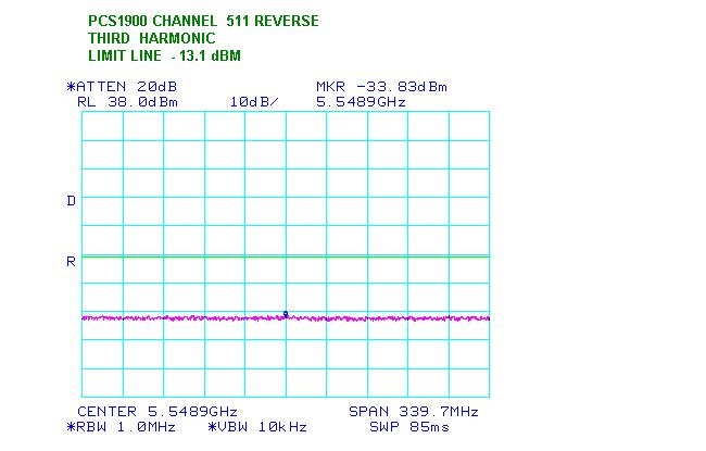
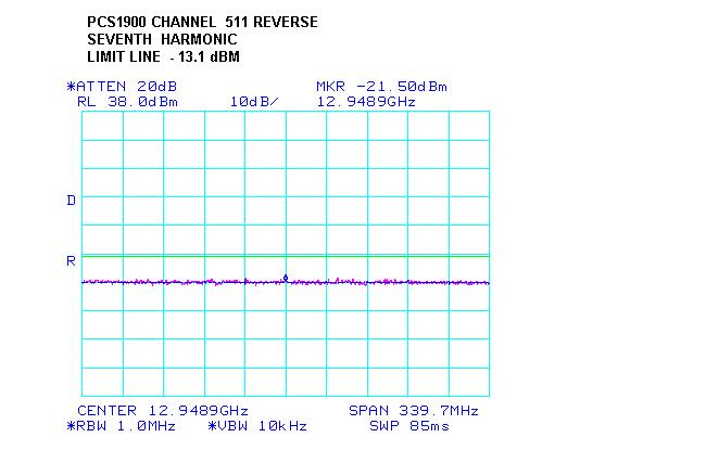
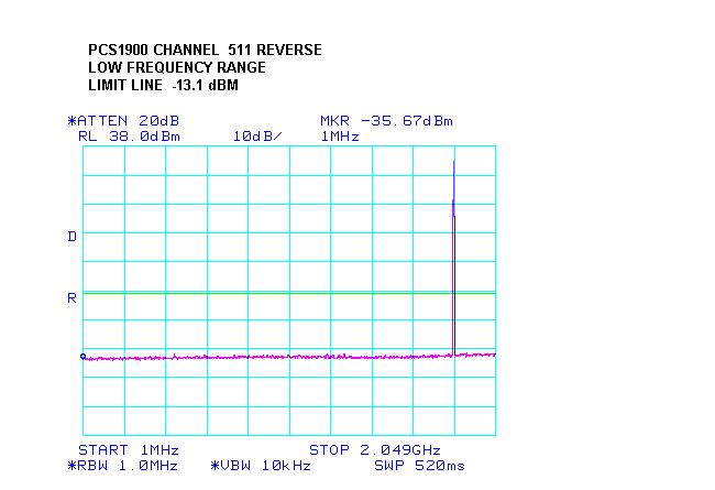
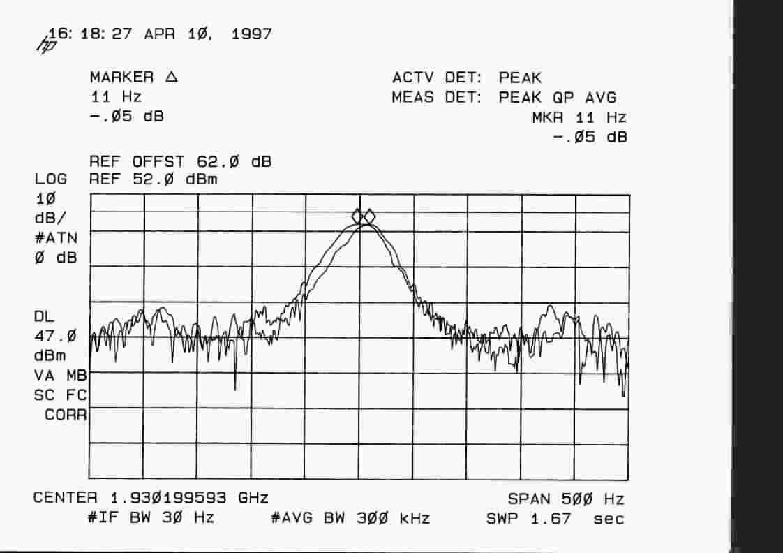
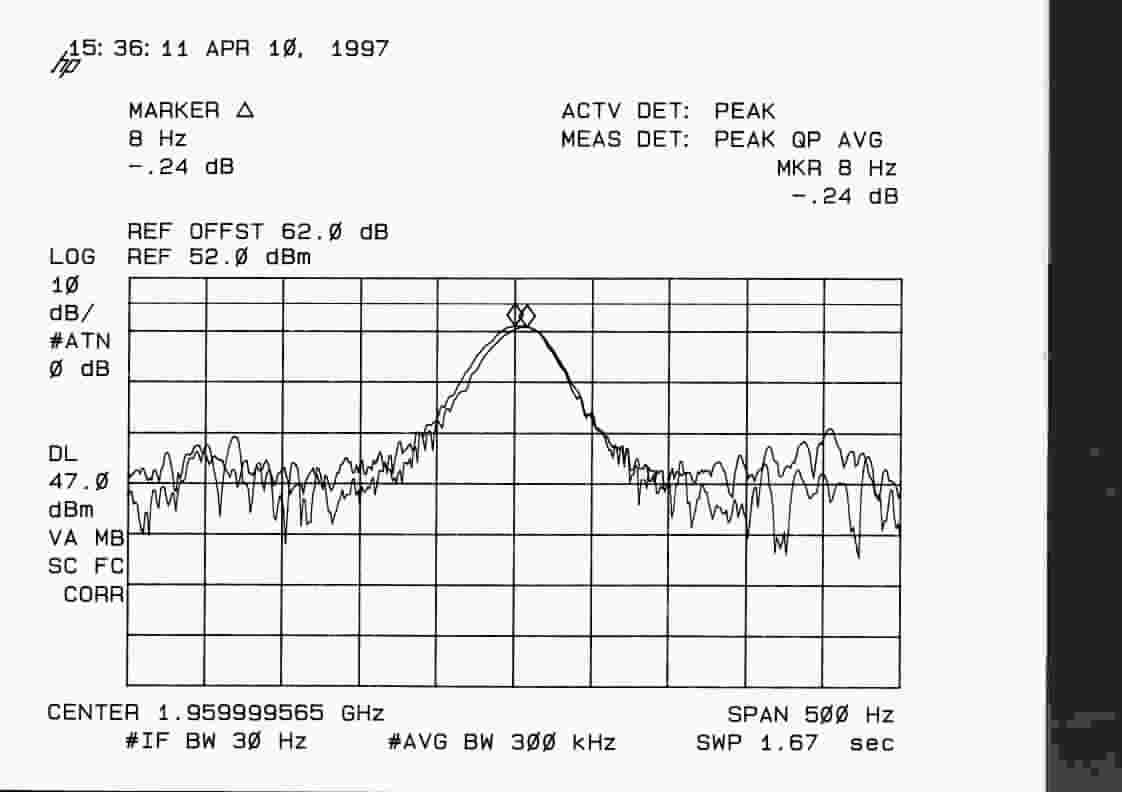
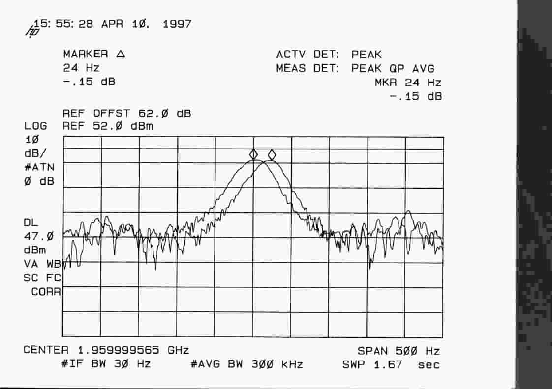
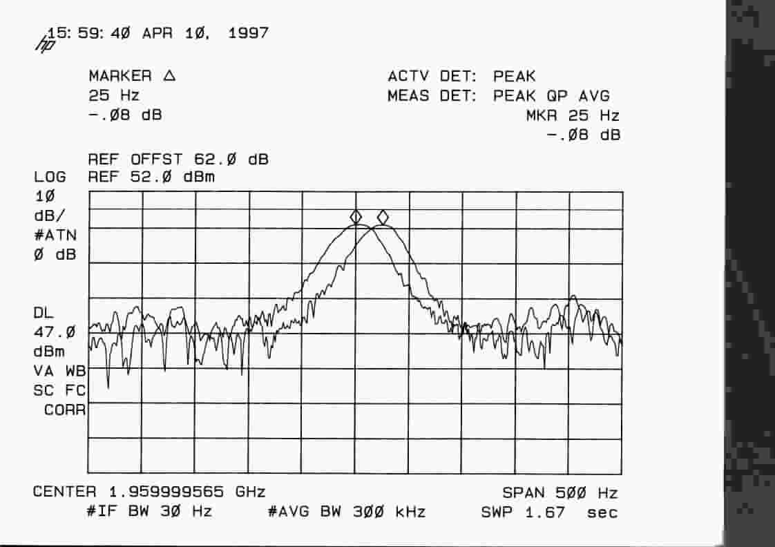
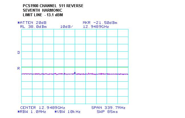
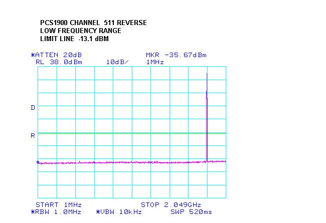
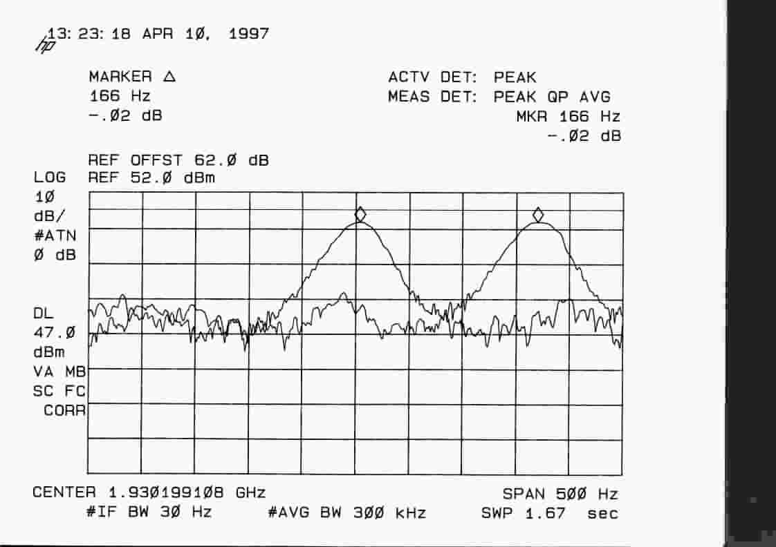
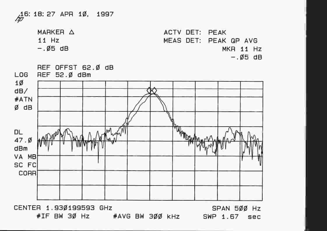
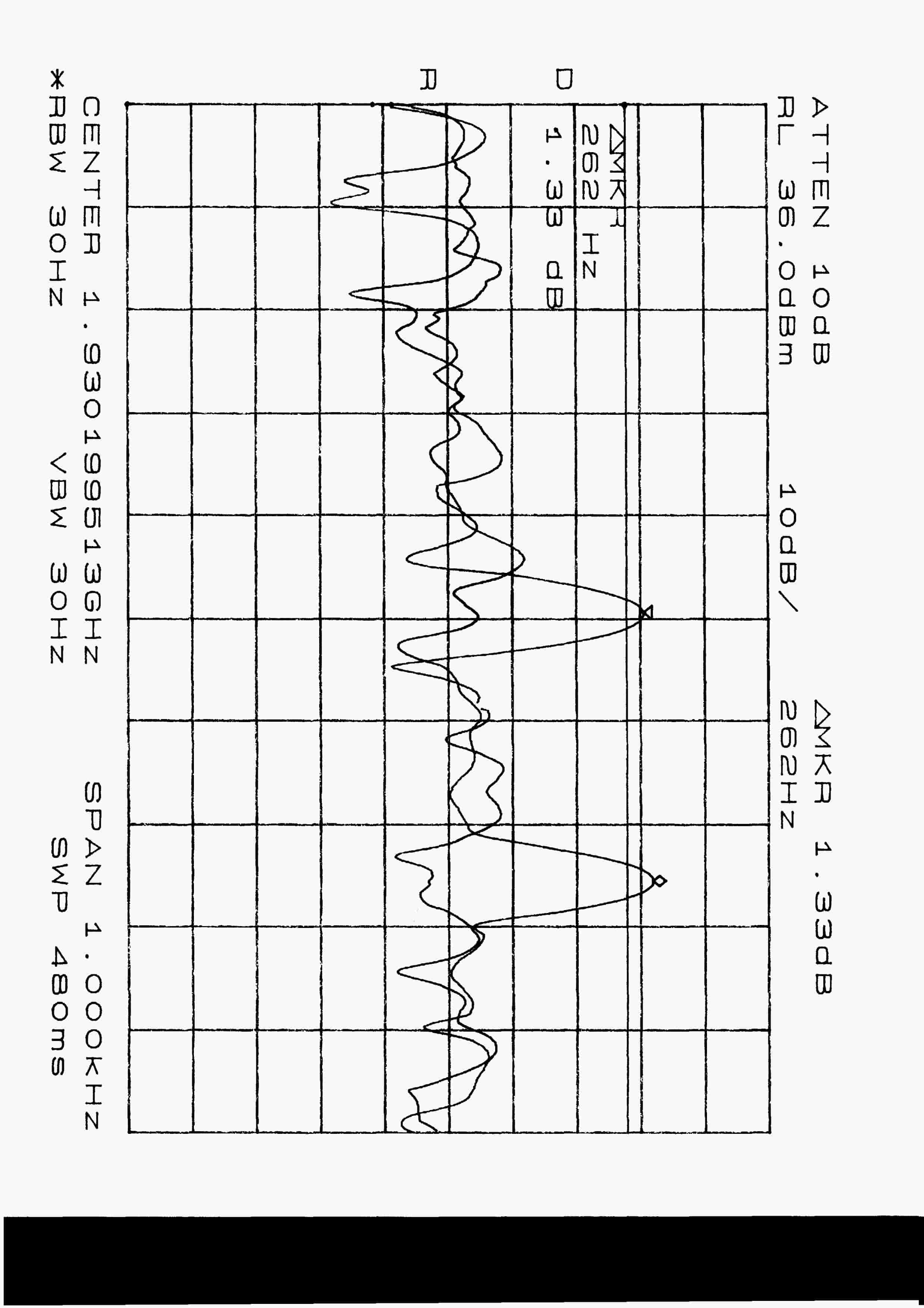
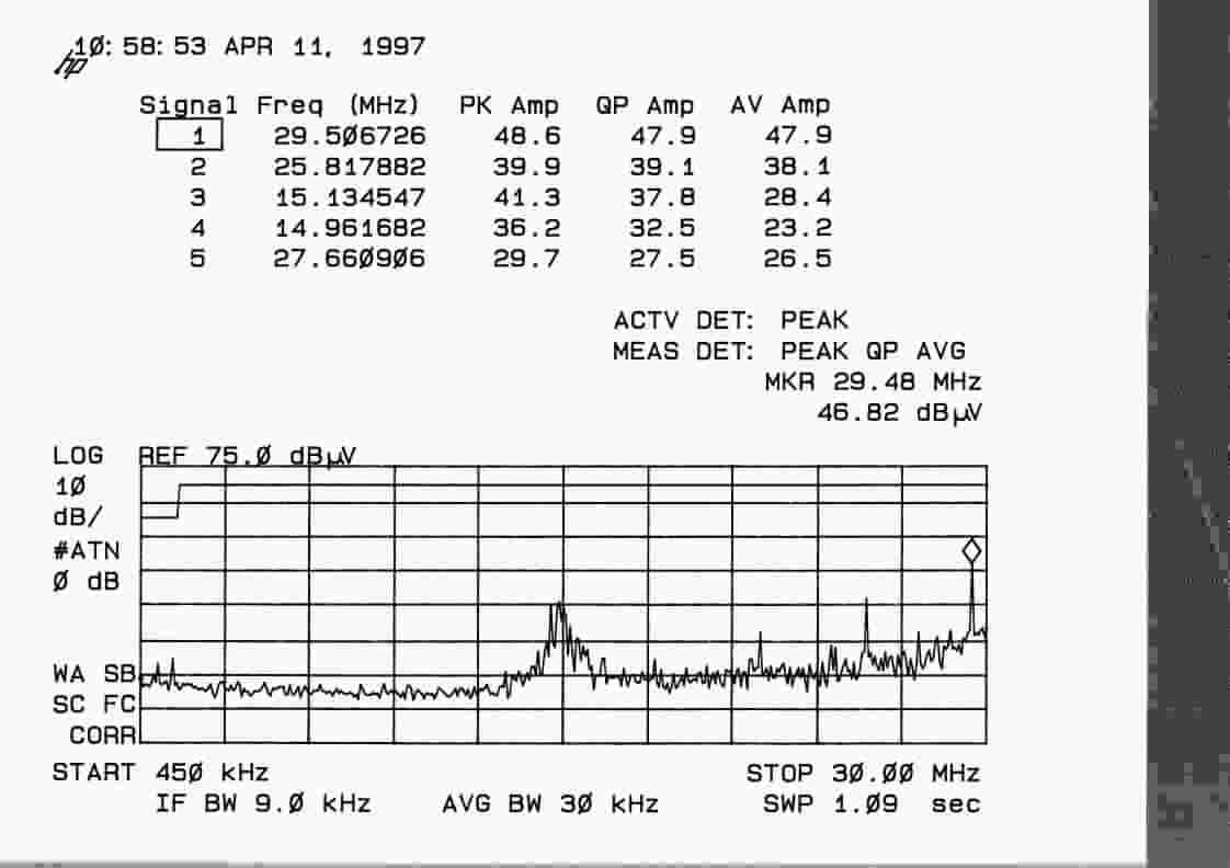
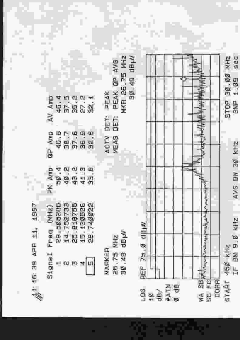
FCC ID: LN4P-41-AOO818 SEPTEMBER 15, 1998 Federal Communications Commission Authorization and Evaluation Division 7435 Oakland Mills Road Columbia, MD 21046 Attention:Applications Examiner Applicant:LCC International, Inc. 2300 Clarendon Blvd., Suite 800 Arlington, VA 22201 Equipment: SpectraWave 1900 Base Station Transmitter FCC ID: LN4P-41-AOO818 Specification:47 CFR 24 Type Acceptance Dear Examiner: The following application for Grant of Equipment Authorization is presented on behalf of LCC International, Inc. For their SpectraWave 1900 Base Station Transmitter Enclosed, please find a complete data and documentation package demonstrating that this device complies with the technical requirements of 47 CFR 24, for a Base Station Transmitter. If you have any questions, please contact the undersigned, who is authorized to act as Agent. Sincerely, Chris Harvey Director, EMC Laboratory MET Laboratories, Inc. Safety Certification - EMI - Telecom Environmental Simulation 914 WEST PATAPSCO AVENUE • BALTIMORE, MARYLAND 21230-3432 • PHONE (410) 354-3300 • FAX (410) 354-3313 FCC ID: LN4P-41-AOO818 ENGINEERING TEST REPORT in support of the Application for Grant of Equipment Authorization EQUIPMENT:SpectraWave 1900 Base Station Transmitter FCC ID:LN4P-41-AOO818 Specification:47 CFR 24 On Behalf of the Applicant:LCCInternational, Inc. 2300 Clarendon Blvd., Suite 800 Arlington, VA 22201 Manufacturer:LCCInternational, Inc. 2300 Clarendon Blvd., Suite 800 Arlington, VA 22201 Manufacturer’s Mr.Mike Sciarrotta Representative Test Date(s):April 8 to September 18, 1998 ENGINEERING STATEMENT I ATTEST: the measurements shown in this report were made in accordance with the procedures indicated, and that the emissions from this equipment were found to be within the limits applicable. I assume full responsibility for the accuracy and completeness of these measurements.On the basis of the measurements made, the equipment tested is capable of operation in accordance with the requirements of Part 24 of the FCC Rules under normal use and maintenance. _____________________________ Kenneth Bass EMI Engineer, MET Laboratories _______________________ Supervised by: Chris Harvey Director, EMC Laboratory FCC ID: LN4P-41-AOO818 EMI1116- 3 -September 14, 1998 1.0INTRODUCTION The following data is presented on behalf of the Applicant, LCC International, Inc., as verification of the compliance of LCC International’s SpectraWave 1900 Transmitter to the requirements of 47CFR24. 2.0TEST SITE All testing was conducted at MET Laboratories, Inc., 914 West Patapsco Avenue, Baltimore, Maryland 21230-3493. Radiated emissions measurements were performed on a three-meter open area test site (OATS). A complete site description is on file with the FCC Laboratory Division as 31040/SIT/MET. 3.0TEST EQUIPMENT USED ManufacturerEquipment Calibration DueCal. Interval Hewlett Packard8591E Spectrum Analyzer 1/29/99annual EMCOBiconical Antenna 3104 2/9/99annual EMCOEMCO Log Periodic Antenna 3/20/99annual EMCODouble Ridge Guided Horn 3/20/99annual Hewlett Packard8563A Analyzer5/27/99annual SolarLISN6/30/99annual 4.0EQUIPMENT UNDER TEST CONFIGURATION The EUT was operated in a manner representative of the typical usage of the equipment. During all testing, system components were manipulated within the confines of typical usage to maximize each emission. 5.0TEST TYPE(S) 5.147CFR2.993 Field Strength of Spurious Emissions from Cabinet of EUT 5.247CFR2.985,24.232(a),(b) RF Power Output Measurement 5.347CFR2.989,24.238 Occupied Bandwidth:NOT APPLICABLE:EUT uses no modulation 5.447CFR24.238 Measurement of Spurious Emission inside the 1MHz band adjacent to each frequency block (i.e.spurs+/- 1MHz) 5.547CFR2.991, 24.238(a) Measurement of Conducted Spurious Emissions. Limits = 43+10log(P). 5.647CFR2.995(a)(1) Frequency Stability over -30degreesCto +50degrees C 5.747CFR 2.995(d)(1) Frequency Stability variationsof supply 85% to 115% 5.847CFR15.107 Line Conducted Emissions required FCC ID: LN4P-41-AOO818 EMI1116- 4 -September 14, 1998 6.0TEST RESULTS Test results are presented in the order they appear in section 5.0. Associated plots, graphs, and photographs are referenced at the end of each results section as electronic file names. These files are provided as attachments to this electronic submission. 6.1TEST TYPE: Field Strength of Spurious Emissions from Cabinet of EUT 6.1.1 TECHNICAL SPECIFICATION:2.993; 24.238(a) 6.1.2 TEST DATE(S):6 Aug 98 6.1.3 MEASUREMENT PROCEDURES: As required by §2.993, field strength of spurious radiation measurements were made in accordance with the general procedures of ANSI C63.4-1992 "Methods of Measurement of Radio- Noise Emissions from Low-Voltage Electrical and Electronic Equipment in the Range of 9kHz to 40 GHz". Preliminary radiated emission measurements were performed inside a shielded chamber with all digital signal generators on and terminated. The frequency list from the preliminary measurements was used as a guide for making final measurements on an 10 meter open area test site. The unit was scanned over the frequency range of 9kHz to 20GHz. The Radiated Spurious Emissions Limit is obtained by the following: The radiated spurious emissions limit is obtained by the following: Based on an input power (as measured at the transmitter output) of 20 watts: P o = 20 W As per 2.993 (a), it is assumed this power is to be fed to a half-wave tuned dipole. Using a conversion formula for distance, the field strength at one meter can be derived: As per 24.238, the spurious emissions must be attenuated by 43 + log(P) which is: Therefore, the limit for spurious emissions is: At 3 meters measurement distance, the limit is; Again, according to 24.238, all signals must be attenuated by 56 dB; Install Equation Editor and double- click here to view equation. Install Equation Editor and double- click here to view equation. Install Equation Editor and double- click here to view equation. Install Equation Editor and double- click here to view…
Text truncated - open the document above for the full version.
Test Report
Again, according to 24.238, all signals must be attenuated by 56 dB; Therefore, the limit for spurious emissions for a test distance of 10 meters is: SUBJECT:Radiated EmissionsMET REPORT:EMI1116 Unmodulated CarrierMFG:LCC International, Inc. FCC Part 24TESTED BY:Kenneth Bass TEST DATE(S):6 Aug 1998 EUT:Base Station Transmitter MODEL:Spectrawave 1900 TECHNICAL SPECIFICATION:2.993; 24.238(a) Carrier Emission:20 Watts FREQUENCYEUT AZIMUTH ANTENNAEUT RADIATION ANTENNA FACTOR TEST DISTANCE CABLE LOSS AMP GAIN MINUS FILTER LOSS FIELD STRENGTH LIMITS (MHz)(Degrees)POL (H/V) HGT (m) (dBμV)(dB/m)(m)(dB)(dBμV)(dBuV/m) (dBuV/m) 206.54180H2.023.5417.332.8633.3084.39 206.5445V1.018.5018.532.8627.6384.39 221.30180H1.525.2716.633.2534.6684.39 221.3045V1.020.6016.633.2529.9984.39 250.800H1.524.2516.533.2533.5484.39 250.80180V1.524.5017.733.2534.9984.39 272.93135H3.024.7115.333.2529.8084.39 272.93180V2.021.8915.433.2530.0884.39 339.32135H2.523.8215.433.8132.5784.39 339.32180V2.021.0315.333.8129.6884.39 365.13180H2.522.8116.133.8132.2684.39 365.130V1.519.2215.933.8128.4784.39 Install Equation Editor and double- click here to view equation. Equipment meets the specifications of 2.985; 2.993; 24.238(a)
Contact Information
Applicant
Michael L. Sciarrotta(Manager, Systems Engineering)
703-873-2529
Technical Contact
MET Laboratories, Inc.Ken H Bass
[email protected](410)354-3300
914 West Patapsco Ave. · Baltiomore, Maryland · United States
Non-Technical Contact
MET Laboratories, Inc.Terri Wolf
[email protected](410354-3300
Test Firm
MET Laboratories, Inc.John Mason
Technical Specifications
| # | Rule Parts | Frequency Range | Power Output | Emission | Tolerance |
|---|---|---|---|---|---|
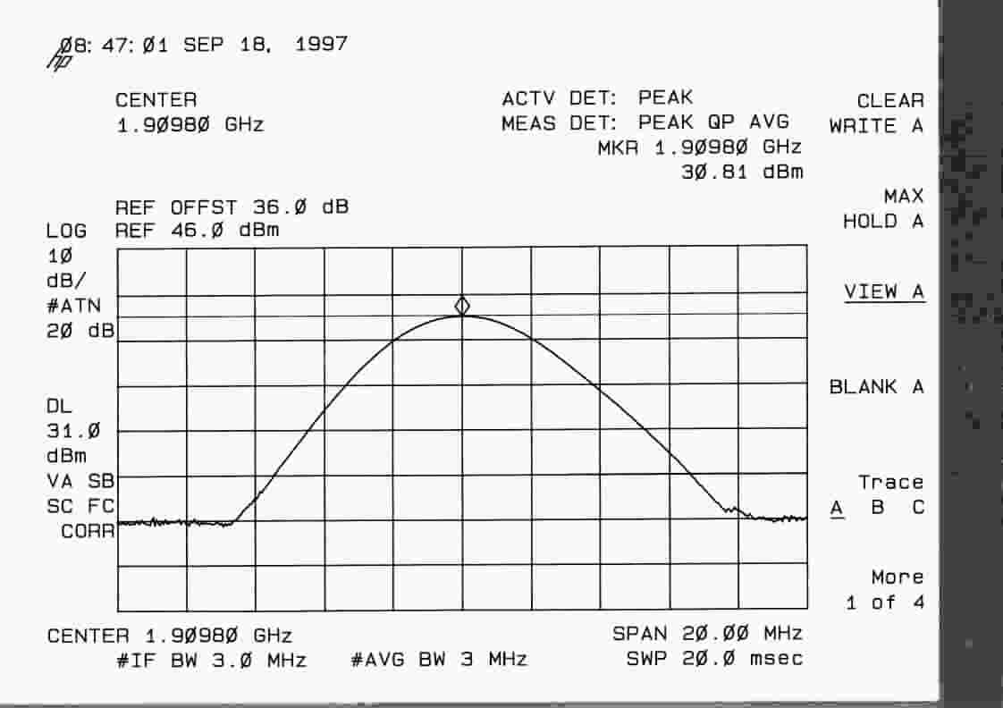
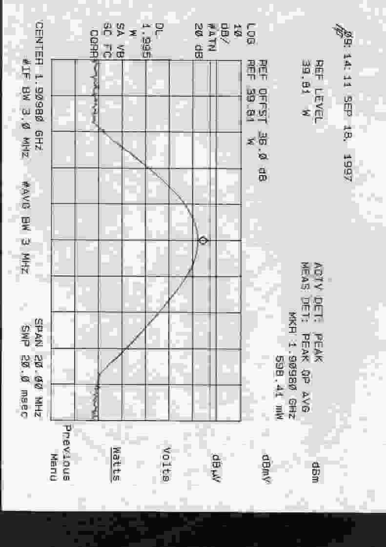
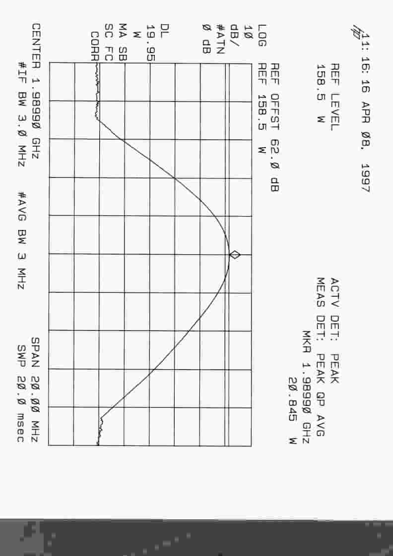
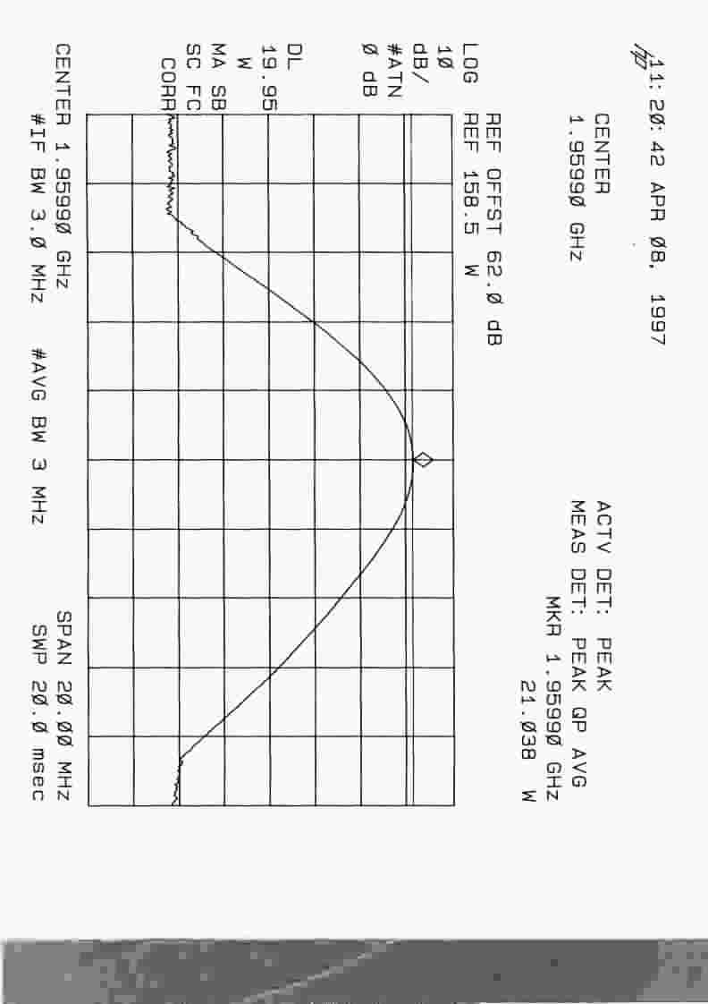
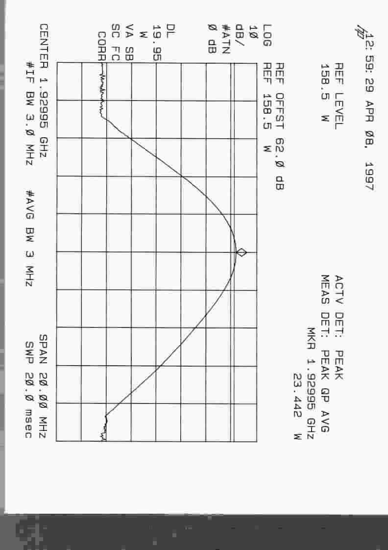
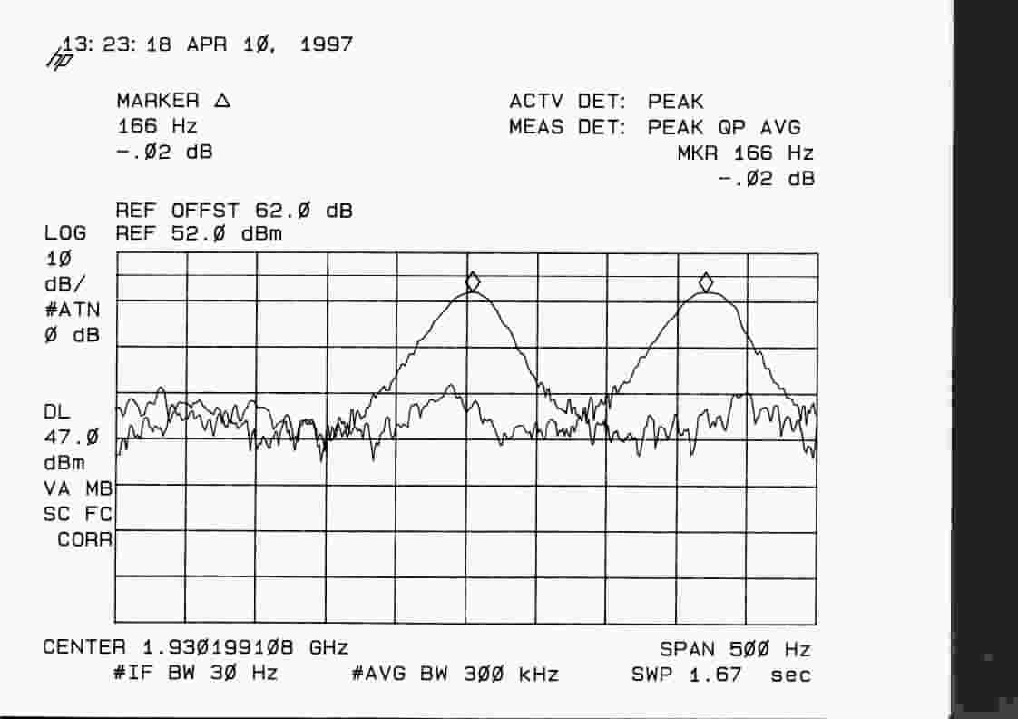
| 2 | 24E | 1.93 GHz - 1.99 GHz | 23.4 W | NON | 262 Hz |