N5VVAC02Vehicle Asset Communicator
I.D. Systems Inc.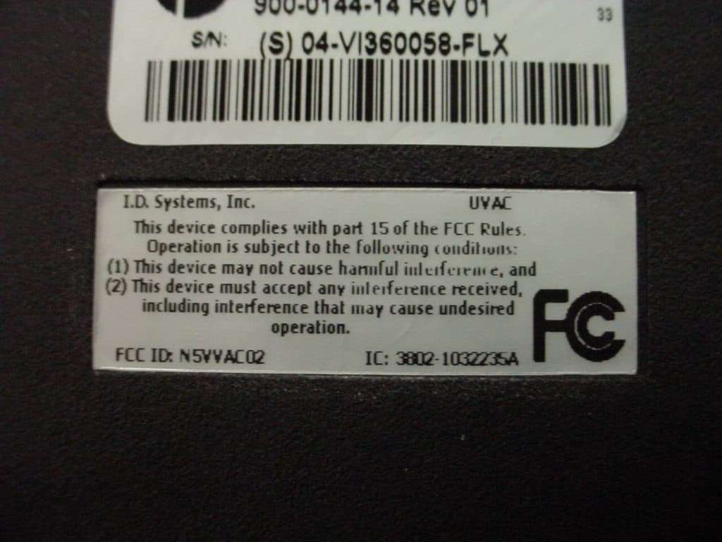
Click to zoom
Application Details
- Equipment Class
- DXX - Part 15 Low Power Communication Device Transmitter
- Date of Grant
- Apr 09, 2006
- Application Purpose
- Original Equipment
- Date of Application
- Apr 09, 2006
- Equipment Note
- Vehicle Asset Communicator
- Frequency Range
- 902.00000000 - 928.00000000
- Company
- I.D. Systems Inc.
- Country
- United States
Documents & Files
Document Text
Text extracted from the exhibit documents filed with the FCC. Open a document above to read the original.
Users Manual
I.D. SYSTEMS, INC. VAC™ – Vehicle Asset Communicator™ A Wireless Fleet Management Device VAC User’s Guide Version 3.1.x VAC™ – A WIRELESS FLEET MANAGEMENT DEVICE VAC – User’s Guide VAC™ IDS Gateway™ IDS WAN Console™ © I.D. Systems, Inc. 1 University Plaza • 6 th Floor Hackensack, NJ 07601 Phone 201.996.9000 • Fax 201.996.9144 www.id-systems.com Preface This manual is a user’s guide for the VAC (Vehicle Asset Communicator), a Wireless Fleet Management Device developed by I.D. Systems, Inc. This guide provides the instruction necessary for someone to install, operate and maintain the VAC device in a vehicle. Note: This user’s guide may change without notice due to enhancements or changes to VAC. Related Documents Vehicle Survey (Doc. #: 026-1000-01) Publication History Version Date Changes 2.5.x 9.18.02 Initial 2.6.x 10.25.02 New Modules: Seatbelt monitor & Battery rotation, new installation screens and color coded connector labels 2.7.x 01-03-03 Add Ext Reader Test, Ext LED Test, Security Features 2.8.x 08-07-03 Add Critical OSHA Shutdown, Blank VAC In Motion 3.0.x 11-03-03 Now Using New Enclosure 3.1.x 03-11-04 O/T versions for new enclosure Disclaimer and Limitation of Liability I.D. Systems, Inc. assumes no responsibility for any damage or loss resulting from the use of its products or services. I.D. Systems assumes no responsibility for any loss or claims by third parties, which may arise through the use of its products or services. The information disclosed herein is the exclusive property of I.D. Systems and no part of this information may be reproduced or transmitted in any form or by any means including electronic storage, reproduction, execution or transmission without the prior written consent of I.D. Systems. The information contained in this document is subject to change without notice and should not be construed as a commitment by I.D. Systems unless such commitment is expressly given in writing. FCC Compliance Statement Compliance Statement (Part 15.19) This device complies with Part 15 of the FCC Rules. Operation is subject to the following two conditions: 1. This device may not cause harmful interference, and 2. This device must accept any interference received, including interference that may cause undesired operation. Warning (Part 15.21) Changes or modifications not expressly approved by the party responsible for compliance could void the user’s authority to operate the equipment. This portable transmitter with its antenna complies with FCC’s RF exposure limits for general population/uncontrolled exposure. Table of Contents I.D. Systems, Inc. One University Plaza, Hackensack, NJ 07601 000-0144-01 Tel: 201-996-9000; Fax 201-996-9144; email: [email protected] Page 5 of 42 Table of Contents TABLE OF CONTENTS.......................................................................................................................................................................................... 5 INTRODUCTION....................................................................................................................................................................................................... 7 SYSTEM OVERVIEW................................................................................................................................................................................................. 7 INSTALLATION......................................................................................................................................................................................................... 9 WARNINGS............................................................................................................................................................................................................. 9 STANDARD HARDWARE FOR INSTALLATION....................................................................................................................................................... 9 TOOLS REQUIRED FOR INSTALLATION (NOT SUPPLIED)................................................................................................................................9 SYSTEM CONNECTIONS OVERVIEW................................................................................................................................................................... 10 INSTALLATION SUMMARY.................................................................................................................................................................................... 10 BEFORE STARTING THE INSTALLATION............................................................................................................................................................. 10 INSTALLING THE VAC (AND OPTIONAL ID READER)..................................................................................................................................... 11 Selecting the VAC Mounting Location.............................................................................................................................................................. 11 Mounting the VAC............................................................................................................................................................................................. 11 INSTALLING VAC-TO-PCM HARNESS............................................................................................................................................................. 12 Vehicle Cable Harness...................................................................................................................................................................................... 12 Selecting the System’s Power and Ground Connections.................................................................................................................................. 13 FINISHING THE INSTALLATION............................…
Text truncated - open the document above for the full version.
External Photos
ID Systems, Inc. Vehicle Asset Communicator FCC ID#: N5VVAC02 Photo One – External Front View of Communicator ID Systems, Inc. Vehicle Asset Communicator FCC ID#: N5VVAC02 Photo Two – External Back View, Showing FCC ID Label ID Systems, Inc. Vehicle Asset Communicator FCC ID#: N5VVAC02 Photo Three – External Close Up of FCC ID Label
ID Label/Location Info
Document Title LABEL, FCC, UVAC 02 Rev ECN No. Revision Description Eff. Date Approved A B - 060020 Production Release FCC ID AND INDUSTRY OF CANADA ID WERE INCORRECT This document contains confidential information that is proprietary to ID Systems, Inc. Neither the document nor the information contained therein should be disclosed or re produced in whole or in part, without the express written consent of ID Systems, Inc. Approval Date Approval Date Author: Approved: Approved: Approved: I.D. Systems, Inc. Hackensack, NJ Filename: 279-0144-05B.doc Application: MS Word Revision Level Release Number Document Number: 279-0144-05 B RN04- Page 1 of 2 064-0001-02 A 1. Material: Ref Brady Corp. material, “B-773” (Metallized polyester with permanent pressure sensitive adhesive, matte finish) 2. Content: 1. Image shown is 200% scale 2. Text is to be Arial Bold font, 4pt. and is to be centered within the label perimeter. 1.70 ID Systems, Inc 279-0144-05 Rev B Page 2 of 2 I.D. Systems, Inc.·UVAC This device complies with part 15 of the FCC Rules. Operation is subject to the following conditions: (1) This device may not cause harmful interference, and (2) This device must accept any interference received, including interference that may cause undesired operati n. o FCC ID: N5VVAC02 · IC: 3802-1032235A .58
Internal Photos
ID Systems, Inc. Vehicle Asset Communicator FCC ID#: N5VVAC02 Photo One – Internal Open for Inspection ID Systems, Inc. Vehicle Asset Communicator FCC ID#: N5VVAC02 Photo Two – Internal RF Section, Component Side, Shield Removed ID Systems, Inc. Vehicle Asset Communicator FCC ID#: N5VVAC02 Photo Three – Internal RF Section, Non-Component Side ID Systems, Inc. Vehicle Asset Communicator FCC ID#: N5VVAC02 Photo Four – Internal Close Up of Antenna Connector ID Systems, Inc. Vehicle Asset Communicator FCC ID#: N5VVAC02 Photo Five – Internal Close Up of Antenna ID Systems, Inc. Vehicle Asset Communicator FCC ID#: N5VVAC02 Photo Six – Internal Close Up of Antenna Port ID Systems, Inc. Vehicle Asset Communicator FCC ID#: N5VVAC02 Photo Seven – Internal Antenna Connection
Test Report
L.S. Compliance, Inc. W66 N220 Commerce Court Cedarburg, WI 53012 262-375-4400 Fax: 262-375-4248 COMPLIANCE TESTING OF: UVAC PREPARED FOR: I.D. Systems, Inc. Attn.: Mr. Leonard Pimentel One University Plaza Drive Suite 600 Hackensack, NJ 07601 TEST REPORT NUMBER: 304490 TX TCB Rev. 1 TEST DATE(S): December 30 th , 2004 and January 10 th & December 17 th , 2005 All results of this report relate only to the items that were tested. This report is not to be reproduced, except in full, without written approval of L. S. Compliance, Inc. L.S. Compliance, Inc. Page 2 of 24 Test Report Number: 304490 TX TCB Rev. 1 Prepared For: I.D. Systems, Inc. Table of Contents Section Description Page Index 2 1 L. S. Compliance in Review 3 2 Signature Page 4 3 Product and General Information 5 4 Introduction 5 5 Product Description 5 6 Test Requirements 6 7 Summary of Test Report 6 8 Radiated Emissions Test 7-16 9 Conducted Emissions Test, AC Power Line 17-21 10 Band-Edge Measurements 22 11 Frequency and Power Stability across input voltage 23 Appendix A Test Equipment List 24 L.S. Compliance, Inc. Page 3 of 24 Test Report Number: 304490 TX TCB Rev. 1 Prepared For: I.D. Systems, Inc. 1. L. S. Compliance In Review L.S. Compliance - Accreditations and Listing’s As an EMC Testing Laboratory, our Accreditation and Assessments are recognized through the following: A2LA – American Association for Laboratory Accreditation Accreditation based on ISO/IEC 17025 : 1999 with Electrical (EMC) Scope of Accreditation A2LA Certificate Number: 1255.01 Federal Communications Commission (FCC) – USA Listing of 3 Meter Semi-Anechoic Chamber based on Title 47 CFR – Part 2.948 FCC Registration Number: 90756 Industry Canada On file, 3 Meter Semi-Anechoic Chamber based on RSS-212 – Issue 1 File Number: IC 3088-A On file, 3 and 10 Meter OATS based on RSS-212 – Issue 1 File Number: IC 3088 U. S. Conformity Assessment Body (CAB) Validation Validated by the European Commission as a U. S. Competent Body operating under the U. S. /EU, Mutual Recognition Agreement (MRA) operating under the European Union Electromagnetic Compatibility –Council Directive 2004/108/EC (formerly 89/336/EEC, Article 10.2) Date of Validation: January 16, 2001 Validated by the European Commission as a U.S. Notified Body operating under the U.S./EU, Mutual Recognition Agreement (MRA) operating under the European Union Telecommunication Equipment – Council Directive 99/5/EC, Annex V. Date of Validation: November 20, 2002 Notified Body Identification Number: 1243 L.S. Compliance, Inc. Page 4 of 24 Test Report Number: 304490 TX TCB Rev. 1 Prepared For: I.D. Systems, Inc. 2. Signature Page Prepared By: March 30, 2006 Teresa A. White, Document Coordinator Date Tested By: April 6, 2006 Thomas T. Smith, EMC Engineer Date Tested By: April 6, 2006 Abtin Spantman, EMC Engineer Date Approved By: April 6, 2006 Brian E. Petted, VP of Engineering Date L.S. Compliance, Inc. Page 5 of 24 Test Report Number: 304490 TX TCB Rev. 1 Prepared For: I.D. Systems, Inc. 3. Product and General Information Manufacturer: I.D. Systems, Inc. Date(s) of Test: Dec. 30 th , 2004 and Jan. 10 th & Dec. 17 th , 2005 Test Engineer(s): √ Tom Smith √ Abtin Spantman Ken Boston Model #: UVAC Serial #: (s)04-V1360058-FLX Voltage: +6.4 VDC Operation Mode: Continuous Data Modulation 4. Introduction On Dec. 30 th , 2004 and Jan. 10 th & Dec. 17 th , 2005 a series of Conducted and Radiated Emission tests were performed on one sample of the I.D. Systems, Inc. UVAC, Serial Number (s)04-V1360058-FLX, here forth referred to as the “Equipment Under Test” or “EUT”. These tests were performed using the procedures outlined in ANSI C63.4-2003 for intentional radiators, and in accordance with the limits set forth in FCC Part 15.249 (Industry Canada RSS- 210) for a low power transmitter. These tests were performed by Thomas T. Smith, EMC Engineer and Abtin Spantman, EMC Engineer of L.S. Compliance, Inc. and witnessed by Leonard Pimentel of I. D. Systems, Inc. All Radiated and Conducted Emission tests were performed upon the EUT to measure the emissions in the frequency bands described in FCC Title 47 CFR Part 15, including 15.35, 15.209, 15.249 and Industry Canada RSS-210 to determine whether these emissions are below the limits expressed within the standards. These tests were performed in accordance with the procedures described in the American National Standard for methods of measurement of Radio- Noise Emissions from Low-Voltage Electrical and Electronic Equipment in the Range of 9 kHz to 40 GHz (ANSI C63.4-2003). Another document used as a reference for the EMI Receiver specification was the Comite International Special Des Perturbations Radioelelectriques (CISPR) Number 16-1, 2003. 5. Product Description The device is a half-duplex, fully functional fixed unit, mounted on a forklift or other ground support equipment trucks for vehicle monitoring and asset location. The transceiver operates in the 902-928 MHz spectrum. The radio is by default in receiver mode. The unit can operate in a continuous transmission mode via the user interface. The operator can return the radio to receiver mode through the user interface or by recycling the power. L.S. Compliance, Inc. Page 6 of 24 Test Report Number: 304490 TX TCB Rev. 1 Prepared For: I.D. Systems, Inc. 6. Test Requirements The above mentioned tests were performed in order to determine the compliance of the UVAC with limits contained in various provisions of Title 47 CFR, FCC Part 15, including: 15.31 15.205 15.33 15.207 15.35 15.209 15.37 15.249 7. Summary of Test Report DECLARATION OF CONFORMITY The I. D. Systems, Inc. UVAC was found to MEET the requirements as described within the specification of Title 47 CFR FCC, Part 15.249, Subpart (a); and Industry Canada RSS-210, Section 6.2 for a ‘Non-Momentarily Operated Transmitting Device’. Some emissions are seen to be within 3dB of their respective limits. As these levels are within the tolerances of the test equipment and sit…
Text truncated - open the document above for the full version.
Test Setup Photos
I.D. Systems Test Setup Photos FCC ID: N5V-VAC02 Page 1 of 2 Photos Taken During Radiated Emission Testing Setup for the Radiated Emissions Test I.D. Systems Test Setup Photos FCC ID: N5V-VAC02 Page 2 of 2 Photo(s) Taken During Conducted Emission Testing Setup for the Conducted Emissions Test
Contact Information
Applicant
Gaurav S Sheth
Test Firm
LS Research, LLCRyan Urness
Technical Specifications
| # | Rule Parts | Frequency Range | Power Output |
|---|---|---|---|
| 1 | 15C | 902 MHz - 928 MHz | - |
Other Applications from I.D. Systems Inc.
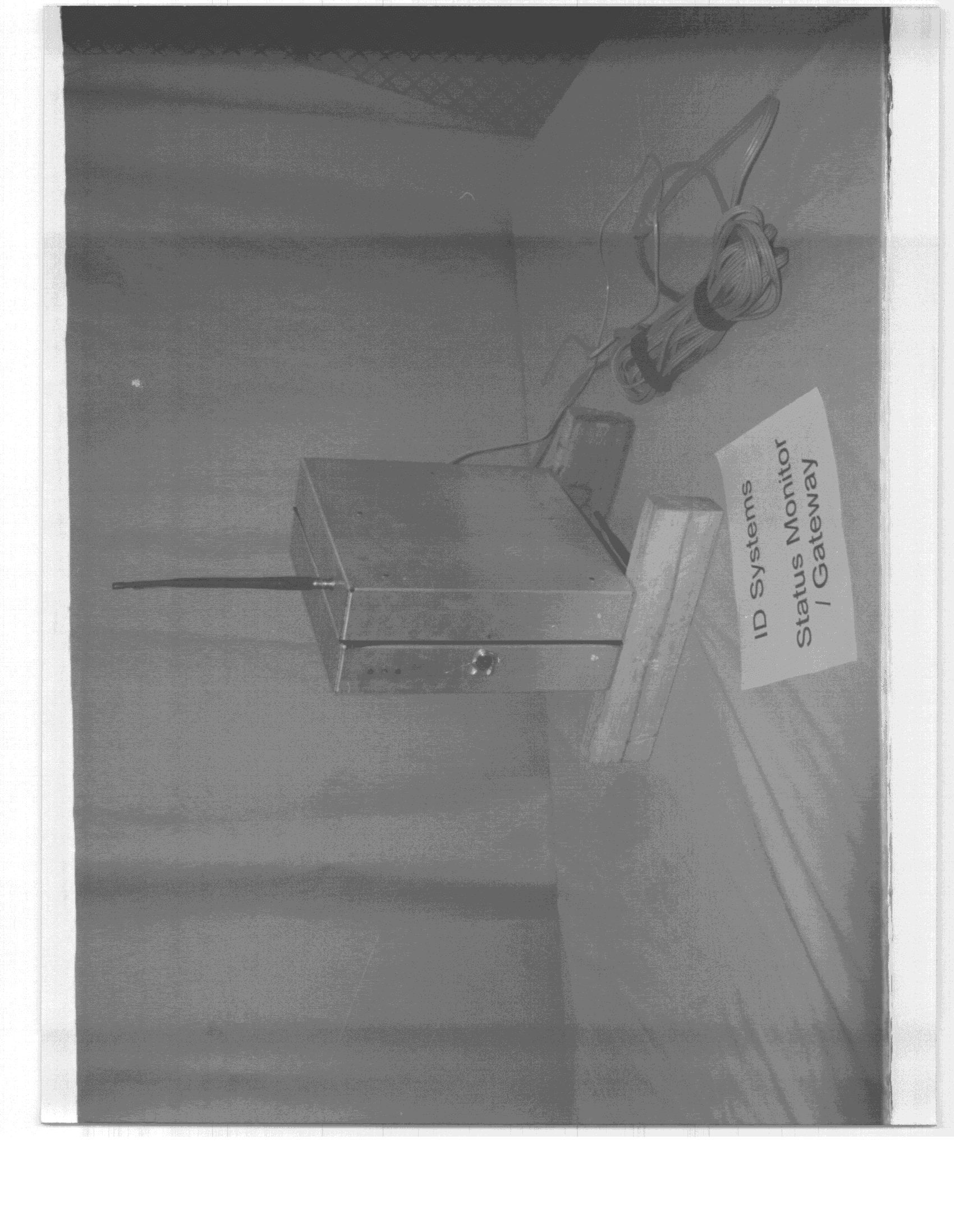
N5VIDS01
Aug 30, 1999DXX - Part 15 Low Power Communication Device Transmitter
Equipment Class
DXX - Part 15 Low Power Communication Device Transmitter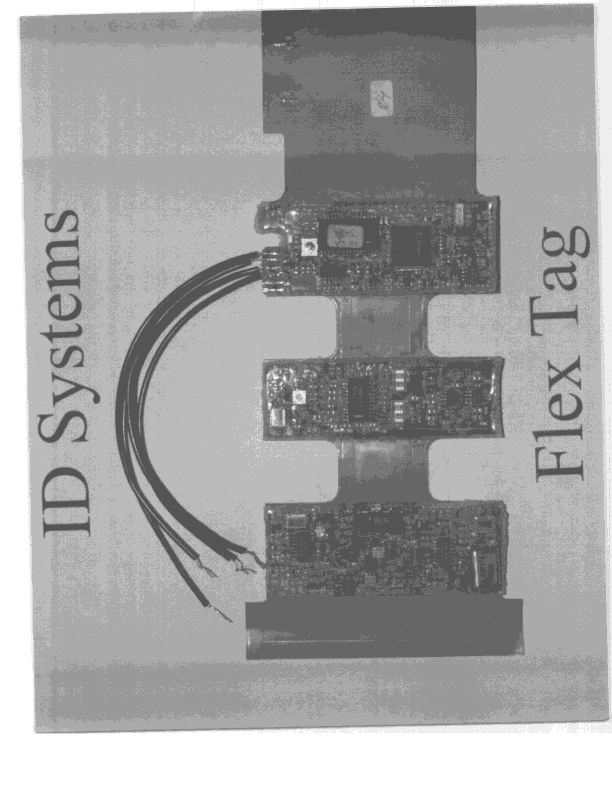
N5VFTG01
Aug 04, 1999DXX - Part 15 Low Power Communication Device Transmitter
Equipment Class
DXX - Part 15 Low Power Communication Device Transmitter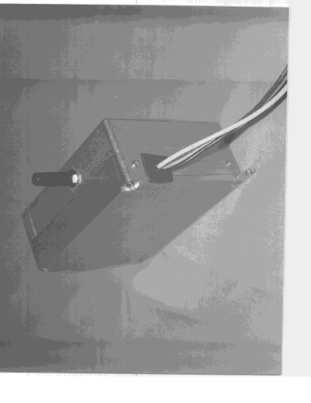
N5VVAC01
Jul 25, 1999DXX - Part 15 Low Power Communication Device Transmitter
Equipment Class
DXX - Part 15 Low Power Communication Device Transmitter