N6DLPX2ALow Power Inventory Transmitter, Model LPX2A
HiTech Equipment Corporation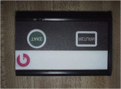
Click to zoom
Application Details
- Equipment Class
- DSC - Part 15 Security/Remote Control Transmitter
- Date of Grant
- Jun 11, 2002
- Application Purpose
- Original Equipment
- Date of Application
- Jun 11, 2002
- Equipment Note
- Low Power Inventory Transmitter, Model LPX2A
- Frequency Range
- 433.92000000 - 433.92000000
- Company
- HiTech Equipment Corporation
- Country
- United States
Documents & Files
Document Text
Text extracted from the exhibit documents filed with the FCC. Open a document above to read the original.
Users Manual
User Instructions LPX2 Designed and Developed by HiTech Equipment Corporation 9672 Via Excelencia San Diego, California 92126 (619) 566-1892 Operation The LPX2 reads the users input from either the TAKE or RETURN buttons on the transmitter. Based on this user input, the transmitter’s microprocessor outputs a corresponding packet of data, which is then modulated and radiated via antennae to a local receiver. The information is then demodulated by a local receiver, which outputs the communicated information. This information is then transferred to a local database. Instructions: When an item is removed press the TAKE button. When an item is replaced press the RETURN button. There are no other functions for the LPX2. No Setup is necessary Caution: Any changes or modifications not expressly approved by HiTech Equipment Corporation could void the user’s authority to operate the LPX2.
Block Diagram
ANTENNA 433.92MHz L.O. 315MHz L.O. Data Modulated Data MIcrocontroller with internal 4MHz
External Photos
CASE TOP CASE SIDE OPEN CASE BOTTOM
ID Label/Location Info
SIZE: 2.0” x 0.40” Color: Black This device complies with Part 15 of the FCC Rules. Operation is subject to the following two conditions: (1) This device may not cause harmful interference, and (2) This device must accept any interference received including interference that may cause undesirable operation. Manufactured for Pyxis Corp. by HiTech Equipment Corp. www.hte.com FCC ID: N6DLPX2A
Internal Photos
BOARD BOTTOM BOARD TOP
Operational Description
Operation The LPX2 reads the users input from either the TAKE or RETURN buttons on the transmitter. Based on this user input, the transmitter’s microprocessor outputs a corresponding packet of data, which is then modulated and radiated via antennae to a local receiver. The information is then demodulated by a local receiver, which outputs the communicated information. This information is then transferred to a local database. HiTech Equipment Corporation Proprietary Data HiTech Equipment Corporation, 9672 Via Excelencia, San Diego, CA 92126 - 1- Theory of Operation and Operating Procedures LPX2 Designed and Developed by HiTech Equipment Corporation 9672 Via Excelencia San Diego, California 92126 (619) 566-1892 Introduction The LPX2 is a wireless supply-monitoring transmitter that can be used for the collection of business supply data. This document outlines the principles of operation of this transmitter, and provides information necessary to aid in Federal Communications Commission Certification Procedures. Any questions that are not adequately addressed in this document should be directed to Mr. Ken Arnold HiTech Equipment Corporation at phone # (858) 566-1892. Modulation Format The transmitter data is sent utilizing a Manchester Coding (state change modulation) in which, a zero (0) is represented as a transition from High to Low and a one (1) is represented as a transition from Low to High. Representing a zero (0) is a High time of 250us followed by a Low time of 250us. Representing a one (1) is a Low time of 250us followed by a High time of 250us. Shown in Figure-1. Figure-1 Manchester Coding HiTech Equipment Corporation Proprietary Data HiTech Equipment Corporation, 9672 Via Excelencia, San Diego, CA 92126 - 2- LPX2 message consists of 10 preamble bits followed by a Sync-to-Follow period of ~ 1ms on High state. The Sync bit is a one (1). This is followed with 64 information bits. One entire packet is sent in approximately 38ms. Shown in Figure-2. Figure-2 Packet Structure This packet of bits transmitted alternates twice between 315MHz and 433.92MHz. Thus the total resulting time of transmission for the four packets is ~155ms. Shown in Figure-3. Figure-3 315MHz Transmission Sequence
Schematics
123456 A B C D 654321 D C B A ScaleSheet SizeFCSM No.DWG No.Rev 1 of 1 BLPX2A_RBC HiTech Equipment Corp., Inc. LPX2A_RB Dual Transmitter SW2 SW-PB SW1 SW-PB R9 100K R10 0 OHM R8 100K R1 0 OHM R2 18K R5 100 1% R6 18K R7 430 C2 15pF C3 470pf C4 10pF C8 6.8pf C9 12pF C11 10pF C13 1000pf C14 2.2pF C16 1000pF L1 0 OHM L2 10nH L3 6.8nH BT1 3.0V LITHIUM +3.0V +3.0V +3.0V +3.0V +3.0V +3.0V +3.0V 1 2 34 Y1SAW R02073A 1 2 34 Y2SAW R02101A VDD 1 GP5/CLKIN 2 GP4.OSC2 3 GP3/MCLR 4 GP2/TOCK1 5 GP1 6 GP0 7 VSS 8 U1 PIC 12C509A-04SM 1 TP1 1 TP2 1 TP4 1 TP5 1 TP6 1 TP7 1 TP8 1 TP9 1 TP10 DGND TAKE RETURN 1 TP11 TP 1 TP12 TP 1 2 3 Q1 FMMT5179TA 1 2 3 Q2 FMMT5179T C24 1.5pF C20 2.2pF C22 2.2pF C18 1.5 pF L5 120nH L7 82 nH L6 68 nH CURRENT LOOP TX433 TX315 L20 0 OHM L21 0 OHM 1 TP3 TP C50 470pF
Test Report
TÜV PRODUCT SERVICE 10040 Mesa Rim Road San Diego, CA 92121-2912 Phone 858 546 3999 FAX 858 546 0364 Report No. 201639-03 Page 1 Rev.No 1.0 MEASUREMENT AND TECHNICAL REPORT HITECH EQUIPMENT CORPORATION 9672 Via Excelencia, Suite 1001 San Diego, CA 92126 DATE: 02 May 2002 This Report Concerns: Original Grant: X Class II Change: Equipment Type: Low Power Inventory Transmitter, Model LPX2A Deferred grant requested per 47 CFR 0.457(d)(1)(ii)? Yes: Defer until: No: X Company Name agrees to notify the Commission by: N/A of the intended date of announcement of the product so that the grant can be issued on that date. Transition Rules Request per 15.37? Yes: *No: X (*) FCC Part 2, Paragraphs 15.231(a); (b); (c); 15.107(a); 15.109(a) Report Prepared by: TÜV PRODUCT SERVICE 10040 Mesa Rim Road San Diego, CA 92121-2912 Phone: 858 546 3999 Fax: 858 546 0364 TÜV PRODUCT SERVICE 10040 Mesa Rim Road San Diego, CA 92121-2912 Phone 858 546 3999 FAX 858 546 0364 Report No. 201639-03 Page 2 Rev.No 1.0 TABLE OF CONTENTS Pages 1 GENERAL INFORMATION 3 1.1 Product Description 3 1.2 Related Submittal Grant 4 1.3 Tested System Details 4 1.4 Test Methodology 4 1.5 Test Facility 4 2 SYSTEM TEST CONFIGURATION 5 2.1 Justification 5 2.2 EUT Exercise Software 5 2.3 Special Accessories 5 2.4 Equipment Modifications 5 2.5 Configuration of Tested System 5 3 RADIATED EMISSION EQUIPMENT/DATA 6 Field Strength Calculation 12 4 Deactivation/Bandwidth 13 5 Attestation Statement 18 TÜV PRODUCT SERVICE 10040 Mesa Rim Road San Diego, CA 92121-2912 Phone 858 546 3999 FAX 858 546 0364 Report No. 201639-03 Page 3 Rev.No 1.0 1 GENERAL INFORMATION 1.1 Product Description EUT Description: Low Power Inventory Transmitter, Model LPX2A Power Requirements Voltage: Battery -3V (If battery powered, make sure battery life is sufficient to complete testing.) EUT Power Cable: Not Applicable EUT Software. Revision Level: LPX2 Description: Two-button communication protocol EUT Operating Modes to be Tested - 1. Take button pressed 2. Return button pressed 3. Both take and return buttons pressed. EUT System Components Description Model # Serial # FCC ID # Inventory Transmitter LPX2A N/A Oscillator Frequencies Frequency MHz Derived Frequency Component # / Location Description of Use 315 -- SAW Y1 Local Oscillator 433.92 -- SAW Y2 Local Oscillator 4 -- NC U1 Processor clock internal TÜV PRODUCT SERVICE 10040 Mesa Rim Road San Diego, CA 92121-2912 Phone 858 546 3999 FAX 858 546 0364 Report No. 201639-03 Page 4 Rev.No 1.0 1 GENERAL INFORMATION (continued) 1.2 Related Submittal/Grant None 1.3 Tested System Details The FCC IDs for all equipment, plus descriptions of all cables used in the tested system are: None 1.4 Test Methodology Purpose of Test: To demonstrate compliance with the ANSI C63.4 setup. TEST FCC CFR 47 # PASS/FAIL Radiated Deactivation Emission Bandwidth Conducted Emissions Radiated Emissions Duty Cycle 15.231(b) 15.231(a) 15.231(c) 15.107(a) 15.109(a) 15.231 Pass Pass Pass Battery Pass - no detectable emissions Calculated worst-case of 50% used for measurement (see page 10 and 11) Both Conducted and radiated testing were performed according to the procedures in FCC/ANSI C63.4 and CSA 108.8 - M1983. Radiated testing was performed at an antenna-to-EUT distance of 3 meters (1 - 25 GHz). 1.5 Test Facility The open area test site and conducted measurement data were tested by: TÜV PRODUCT SERVICE 10040 Mesa Rim Road San Diego, CA 92121-2912 Phone: 858 546 3999 Fax: 858 546 0364 The Test Site Data and performance comply with ANSI 63.4 and are registered with the FCC, 7435 Oakland Mills Rd, Columbia Maryland 21046. All Measurement Data is acquired according to the content of FCC Measurement Procedure and ANSI C63.4, unless supplemented with additional requirements as noted in the test report. TÜV PRODUCT SERVICE 10040 Mesa Rim Road San Diego, CA 92121-2912 Phone 858 546 3999 FAX 858 546 0364 Report No. 201639-03 Page 5 Rev.No 1.0 2. SYSTEM TEST CONFIGURATION 2.1 Justification The EUT was initially tested for FCC emission in the following configuration: See Block Diagram. 2.2 EUT Exercise Software None 2.3 Special Accessories None 2.4 Modification None 2.5 Configuration of Tested System See Block Diagram. TÜV PRODUCT SERVICE 10040 Mesa Rim Road San Diego, CA 92121-2912 Phone 858 546 3999 FAX 858 546 0364 Report No. 201639-03 Page 6 Rev.No 1.0 3 RADIATED EMISSION EQUIPMENT/DATA The following data lists the significant emission frequencies, measured levels, correction factor (which includes cable and antenna corrections), the corrected reading, and the limit. See following page(s). See test setup photos for radiated emissions test setup. TÜV PRODUCT SERVICE 10040 Mesa Rim Road San Diego, CA 92121-2912 Phone 858 546 3999 FAX 858 546 0364 Report No. 201639-03 Page 7 Rev.No 1.0 TÜV PRODUCT SERVICE 10040 Mesa Rim Road San Diego, CA 92121-2912 Phone 858 546 3999 FAX 858 546 0364 Report No. 201639-03 Page 8 Rev.No 1.0 TÜV PRODUCT SERVICE 10040 Mesa Rim Road San Diego, CA 92121-2912 Phone 858 546 3999 FAX 858 546 0364 Report No. 201639-03 Page 9 Rev.No 1.0 TÜV PRODUCT SERVICE 10040 Mesa Rim Road San Diego, CA 92121-2912 Phone 858 546 3999 FAX 858 546 0364 Report No. 201639-03 Page 10 Rev.No 1.0 TÜV PRODUCT SERVICE 10040 Mesa Rim Road San Diego, CA 92121-2912 Phone 858 546 3999 FAX 858 546 0364 Report No. 201639-03 Page 11 Rev.No 1.0 TÜV PRODUCT SERVICE 10040 Mesa Rim Road San Diego, CA 92121-2912 Phone 858 546 3999 FAX 858 546 0364 Report No. 201639-03 Page 12 Rev.No 1.0 Field Strength Calculation If a preamplifier was used during the Radiated Emission Testing, it is required that the amplifier gain must be subtracted from the Spectrum Analyzer (Meter) Reading. In addition, a correction factor for the antenna, cable used and a distance factor, if any, must be applied to the Meter Reading before a true field strength reading can be obtained. In the automatic measurement, these considerations are automatically presented as a part of the print out. In the cas…
Text truncated - open the document above for the full version.
Contact Information
Applicant
Ken Arnold(President)
619-566-1892
Test Firm
TUV AmericaJames Owen
Technical Specifications
| # | Rule Parts | Frequency Range | Power Output |
|---|---|---|---|
| 2 | 15.231 | 433.92 MHz - 433.92 MHz | - |
Other Applications from HiTech Equipment Corporation
N6DLPX1
Apr 18, 1999Utility Consumption Transmitter
Equipment Class
DSC - Part 15 Security/Remote Control Transmitter