N76CATX001Club-Alert Golf Club Transmitter
Peggy Berry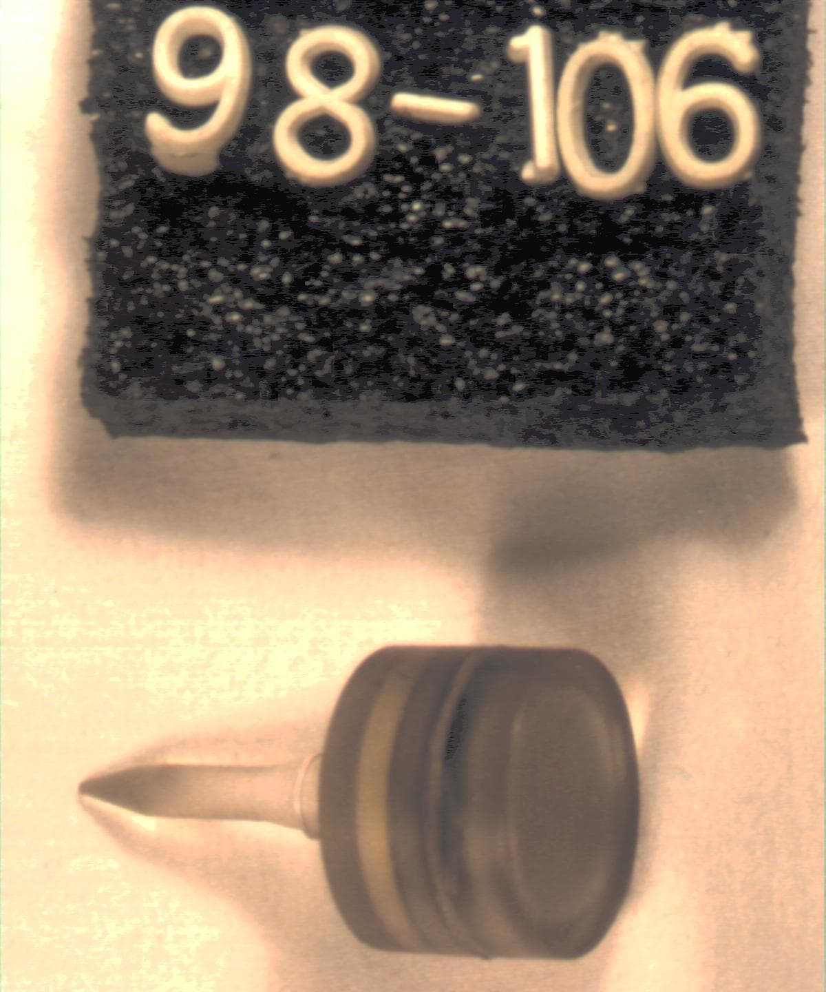
Click to zoom
Application Details
- Equipment Class
- DSC - Part 15 Security/Remote Control Transmitter
- Date of Grant
- Oct 28, 1998
- Application Purpose
- Original Equipment
- Date of Application
- Oct 05, 1998
- Equipment Note
- Club-Alert Golf Club Transmitter
- Frequency Range
- 418.00000000 - 418.00000000
- Company
- Peggy Berry
- Country
- United States
Documents & Files

Document Text
Text extracted from the exhibit documents filed with the FCC. Open a document above to read the original.
Users Manual
Club-Alert Manual The Club-Alert is designed to help you keep all your favorite golf clubs together. The system consists of a Receiver and 5 transmitters. The transmitters are designed to be inserted in the end of a golf club handle using the hole at the top. Gently insert the transmitter in the 5 clubs you are most likely to use around the green and push them fully home. The shape of the transmitter is such that it will remain firmly in place until you wish to remove it. Each transmitter contains a battery that will last for over a year. There is no on/off switch since they remain on all the time. The receiver should be attached to your golf bag or close by, and should be mounted so that as you approach the bag, you can see the indicator lights. To "enable" the system you need to audit your club inventory. You want to do this in the absence of any body else's Club-Alert transmitters, so it is best done before you leave for the course. If this is not possible or if for any reason you wish to re-inventory your clubs, you should remove your Receiver and the clubs with Transmitters at least 100 feet from any other golf clubs possibly carrying Club-Alert Transmitters. The nominal range of the Club-Alert Transmitter is 50 to 60 feet. When satisfactorily placed for and audit, turn the Receiver power switch on (up). The visual (Red and Green lights) and the audible alarms will commence. The audible alarm will cease quickly but the visual alarms will continue. After at least 10 seconds and up to 30 seconds, the audible alarm will signal the number of clubs it has found with a sequence of beeps equal to the number of clubs that it received. While all Club-Alert Transmitters have different codes, they all operate on the same frequency so that any other Club-Alert Transmitters in the area will be received by your Receiver but if the audit was carried out in there absence, your receiver will ignore the other Club-Alert Transmitters. After the audit is complete, the Green light will flash every 8 seconds to let you know that the system is on and functioning. The Red light will remain extinguished until you remove one of your clubs fitted with a Club-Alert Transmitter more than 50 to 60 feet from the Club- Alert Receiver. At that time the Red light will flash at 2 second intervals until you return the club within the range of the Club-Alert Receiver where upon the Red light will extinguish. If the club is out of range of the Club-Alert Receiver, for more than 14 minutes, the Audible alarm will sound a series of beeps. These will continue until the club is returned or until you silence the audible alarm with the switch at the top of your Club-Alert Receiver. The Red light will continue to flash until the club is returned. If the club is still not returned in a further 14 minutes or 28 minutes in total, the Audible alarm will start again. The club-Alert Receiver should be switched off when not in use to conserve the batteries. When replacement is required, the Audible warning will provide short beeps about 60 seconds apart. At that time .the two AA batteries should be replaced. REGULATORY COMPLIANCE STATEMENTS (A) This device complies with Part 15 of the FCC Rules. Operation is subject to the following two conditions: (1) This device may not cause harmful interference, and (2) this device must accept any interference received, including interference that may cause undesired operation. (B) Modification of this device by without prior approval of the manufacturer could result in a condition which would void the user’s authority to operate the equipment.
Cover Letter(s)
Peggy Berry 9550 Ella Lee Lane, #1608 Houston, Texas 77063 October 5, 1998 Federal Communications Commission Authorization & Evaluation Division 7435 Oakland Mills Road Columbia, Maryland 21046 To Whom It May Concern: I, Peggy Berry, hereby authorizes Professional Testing (EMI) Inc. of Round Rock, Texas to operate on its behalf in the matter of FCC approval of the ClubAlert System This item is a short range (< 100ft) intermittent transmitter system intended to alert a user of a missing golf club. Professional Testing has evaluated this item and found it to meet the technical requirements of 47 CFR Part 15, Subpart B (Section 15.231). Professional Testing is authorized to file the necessary forms, exhibits and fees required to facilitate this application. If you have any further questions, please contact me: Peggy Berry (713) 785-3502 (281) 395-7595 ANTI-DRUG CERTIFICATION I, Peggy Berry, certifies that no party to this application (as defined in 47 C.F.R. §1.2002(b)(2) ) is subject to a denial of federal benefits pursuant to Section 5301 of the Anti-Drug Abuse Act of 1988, 21 U.S.C 853a. _____________________________________________________________ DateSignature Title
ID Label/Location Info
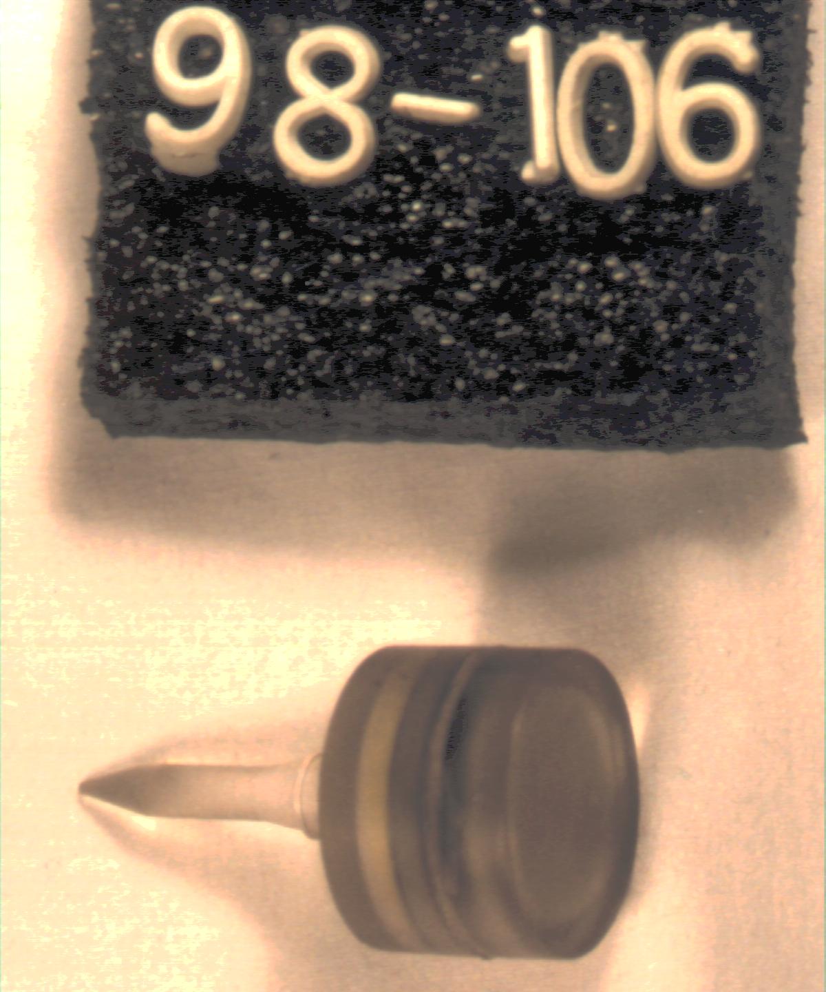
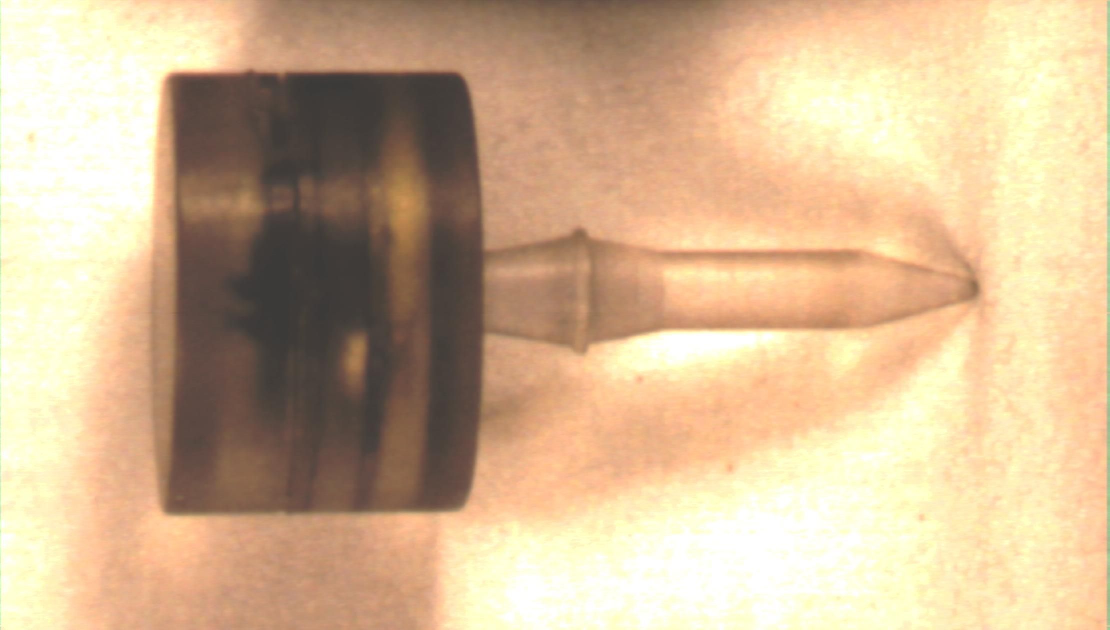
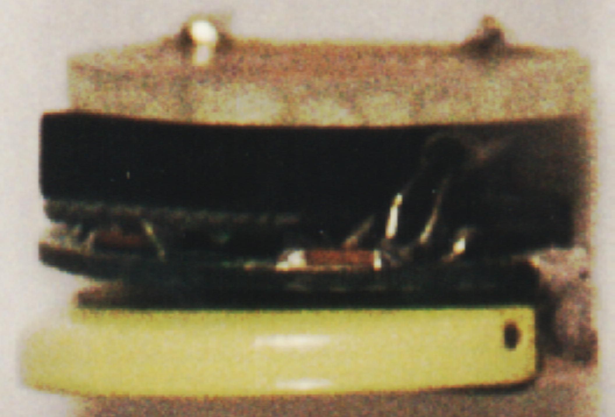
FCCIDN76CATX001 CLUB-ALERT FCCIDLABEL&LOCATION SideViewofEUT
Internal Photos
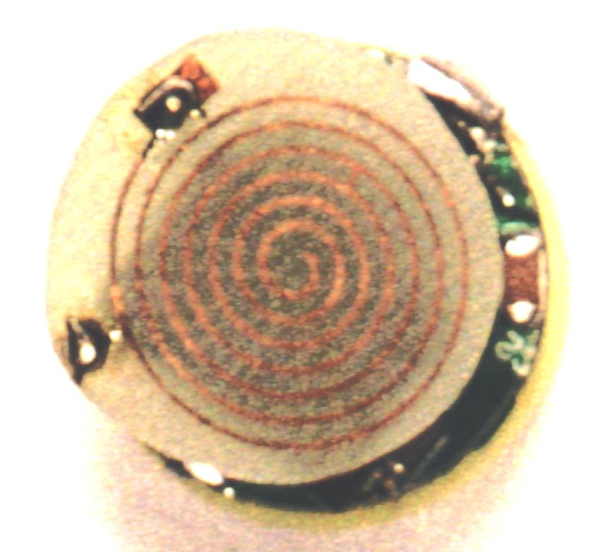
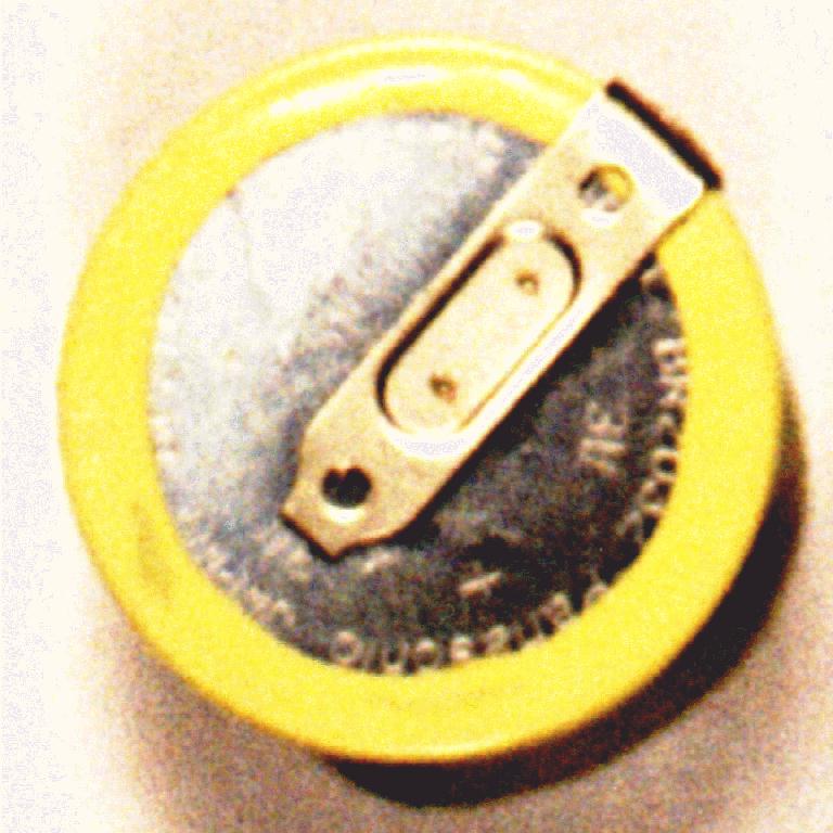
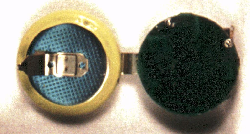
CLUB-ALERTTRANSMITTER EUTLAYOUT CRYSTAL CAPACITORS PROCESSOR CAPACITORS TRANSMITTERCHIP TRANSMITTERCHIP MOTHERBOARD PROCESSOR CRYSTAL ANTENNA NOTE:AntennanotshownforClairity TOPVIEW SIDEVIEW Thisdiagramisincludedaspartofthephotographsubmissionforthisapplicationin ordertoclarifytheassemblyofthisdevice.Duetotherelativelysmallsizeoftheproduct (lessthan2cmindiameter)clearphotographsofthisproductareverydifficult.
Operational Description
OPERATIONAL DESCRIPTION CLUB-ALERT SYSTEM 1.0 General Description The Club-Alert System is comprised of 5 transmitters and one receiver. Each transmitter is installed into the top of a golf club and the receiver is placed near or attached to the golf bag that normally contains the ‘marked’ clubs. Each club transmitter transmits a unique code at specific intervals. The transmitters and receiver are designed to provide a reliable communication link for a distance of approximately 100 feet. The receiver ‘listens’ for each of the club transmitters and provides a visual and audio alarm if a transmitter code is missing. If the missing clubs are placed back within range of the receiver, the warning will automatically cease. 2.0 RF Description The transmitters for the Club-Alert system are comprised of a code generation chip and an RF modulator chip. The output of the RF chip is fed to a spiral antenna in the top of the device. This device is compliant with 47 CFR 15.231 as an periodic transmitter (§15.231 (e)). To minimize the package size, the code generation chip and the RF chip are stacked on top of each other. The identity code of each transmitter module is based on which of the code generation chip outputs is tied to the input of the RF chip. No tuning or alignment of the devices is required. All transmitters and receivers are preset by the manufacturer prior to shipping.
Test Report
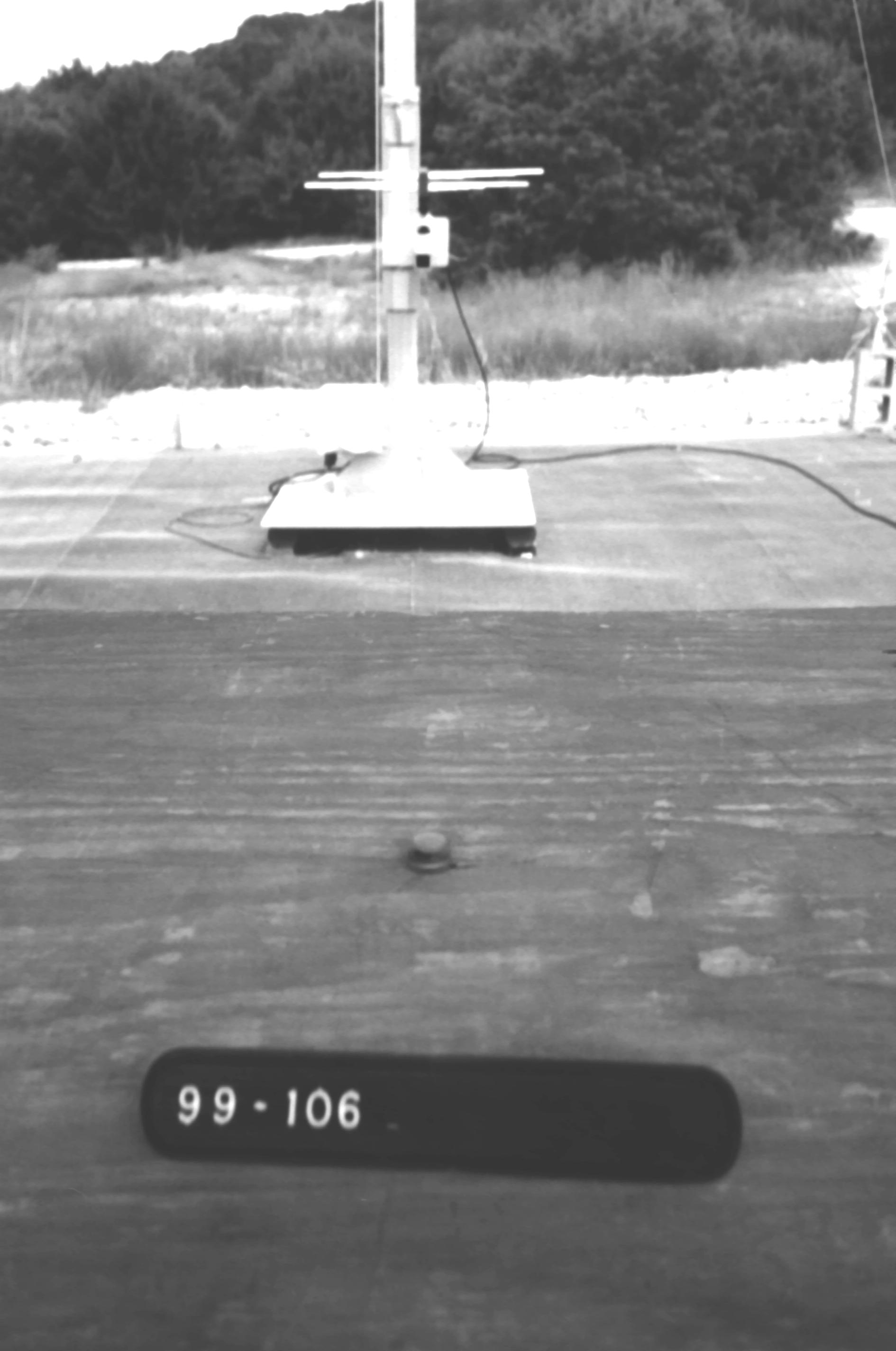
FCC ID: N76CATX001 Prepared for: PEGGY BERRY 9550 Ella Lee Lane, # 1608 Houston, Texas 77063 By: Professional Testing (EMI), Inc. 1601 FM 1460, Suite B Round Rock, Texas 78664 PTI PROJECT: 99-106 Submitted to: Federal Communications Commission Equipment Authorization Division, Application Processing Branch 7435 Oakland Mills Road Columbia, MD 21048 October 1998 FCC Type Certification Test Report of an Intentional Radiator Club-Alert Golf Club Transmitter (Transmitter Portion) FCC ID# N76CATX001 Professional Testing (EMI), Inc.2 of 21 Table of Contents Title Page ..............................................................................................................................................1 Table of Contents...................................................................................................................................2 Certificate of Compliance......................................................................................................................4 Appendices...........................................................................................................................................2 1.0Equipment Under Test (EUT) Description..................................................................................4 1.1Equipment Under Test (EUT) Operation.....................................................................................4 2.0Operational Frequency Measurement and EUT Use Evaluation.................................................4 2.1Test Procedure..............................................................................................................................5 2.2Test Criteria..................................................................................................................................5 2.3Test Results...................................................................................................................................5 3.0Transmission Parametrics.............................................................................................................5 3.1Test Procedure..............................................................................................................................5 3.2Test Criteria..................................................................................................................................6 3.3Test Results...................................................................................................................................6 4.0Occupied Bandwidth Measurements...........................................................................................6 4.1Test Procedure..............................................................................................................................6 4.2Test Criteria..................................................................................................................................6 4.3Test Results...................................................................................................................................7 5.0Peak Output Power.......................................................................................................................7 5.1Test Procedure..............................................................................................................................7 5.2Test Criteria..................................................................................................................................7 5.3Test Results...................................................................................................................................8 6.0Out-of-Band and Restricted Band Emissions Measurements......................................................8 6.1Test Procedure..............................................................................................................................8 6.2Test Criteria..................................................................................................................................8 6.3Test Results...................................................................................................................................9 7.0Antenna Requirement...................................................................................................................9 7.1Evaluation Procedure....................................................................................................................9 7.2Evaluation Criteria........................................................................................................................9 7.3Evaluation Results......................................................................................................................10 9.0Form 731 Information................................................................................................................10 9.1Emission Designator...................................................................................................................10 9.2Output Power..............................................................................................................................10 9.3Main Processor Chip..................................................................................................................11 10.0List of Test Equipment...............................................................................................................11 Appendices Appendix A: Transmission Parametrics Test Data............................................................................12 Appendix B: Occupied Bandwidth Data............................................................................................15 Appendix C: Peak Output Power Test Data.......................................................................................17 Appendix D: Out-of-Band and Restricted Band Radiated Emission Test Data.......................…
Text truncated - open the document above for the full version.
Contact Information
Applicant
Peggy Berry(Proprietor)
(713) 785-3502
Technical Contact
Non-Technical Contact
FLD SystemsTim Davison
[email protected](713) 681-0449
Test Firm
Professional Testing (EMI) Inc.Jeffrey Lenk
Technical Specifications
| # | Rule Parts | Frequency Range | Power Output |
|---|---|---|---|
| 1 | 15C | 418 MHz - 418 MHz | - |