N9FLCR-2000CRF CARD READER
LEEMA PHARMED INC.
Click to zoom
Application Details
- Equipment Class
- DCD - Part 15 Low Power Transmitter Below 1705 kHz
- Date of Grant
- Dec 30, 1998
- Application Purpose
- Original Equipment
- Date of Application
- Oct 27, 1998
- Equipment Note
- RF CARD READER
- Frequency Range
- 0.12500000 - 0.12500000
- Company
- LEEMA PHARMED INC.
- Country
- South Korea
Documents & Files
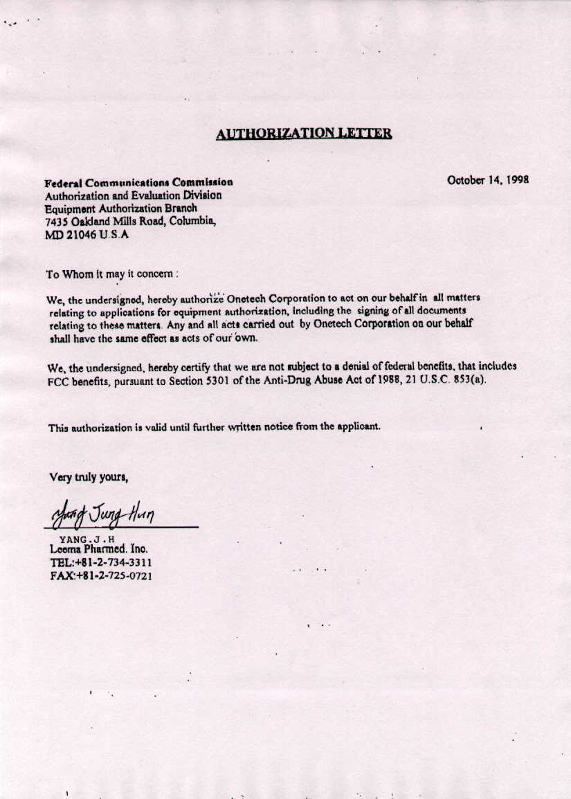
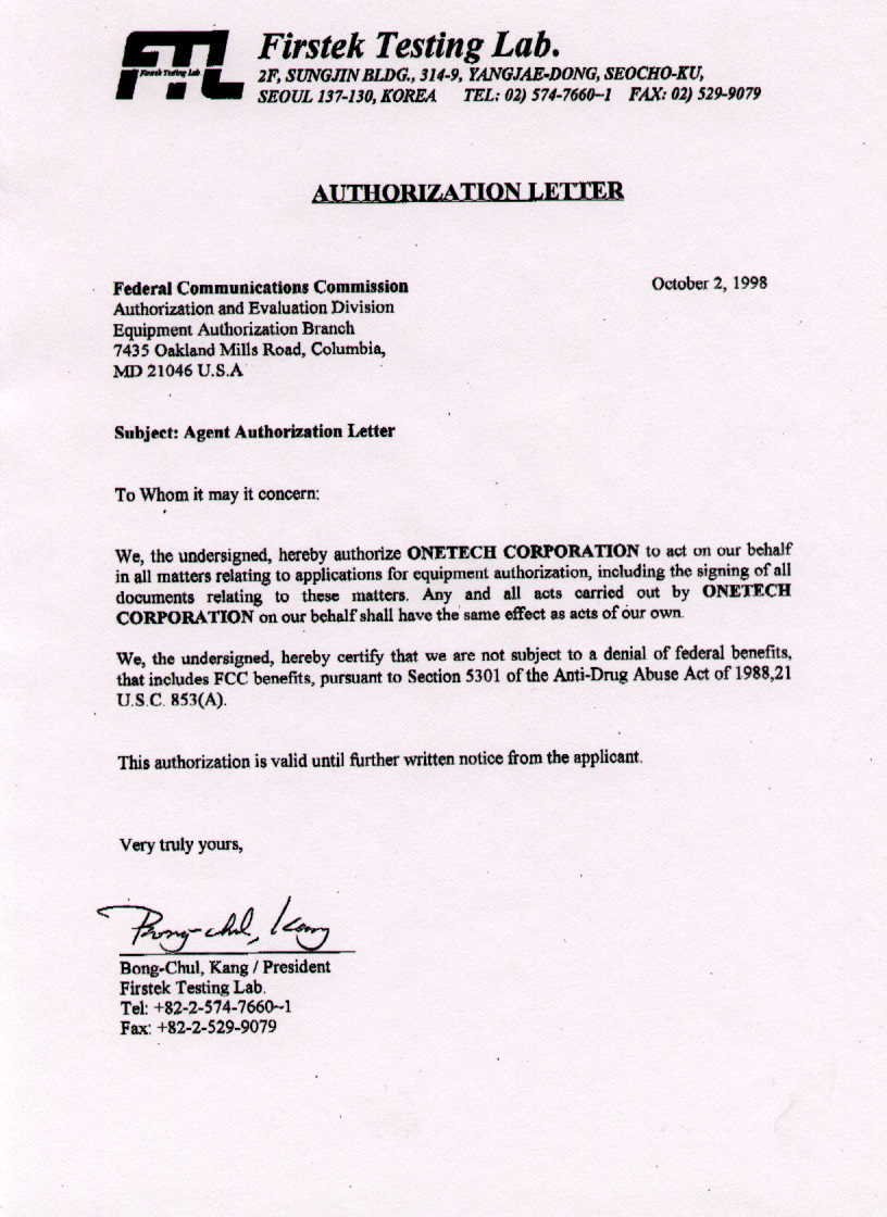
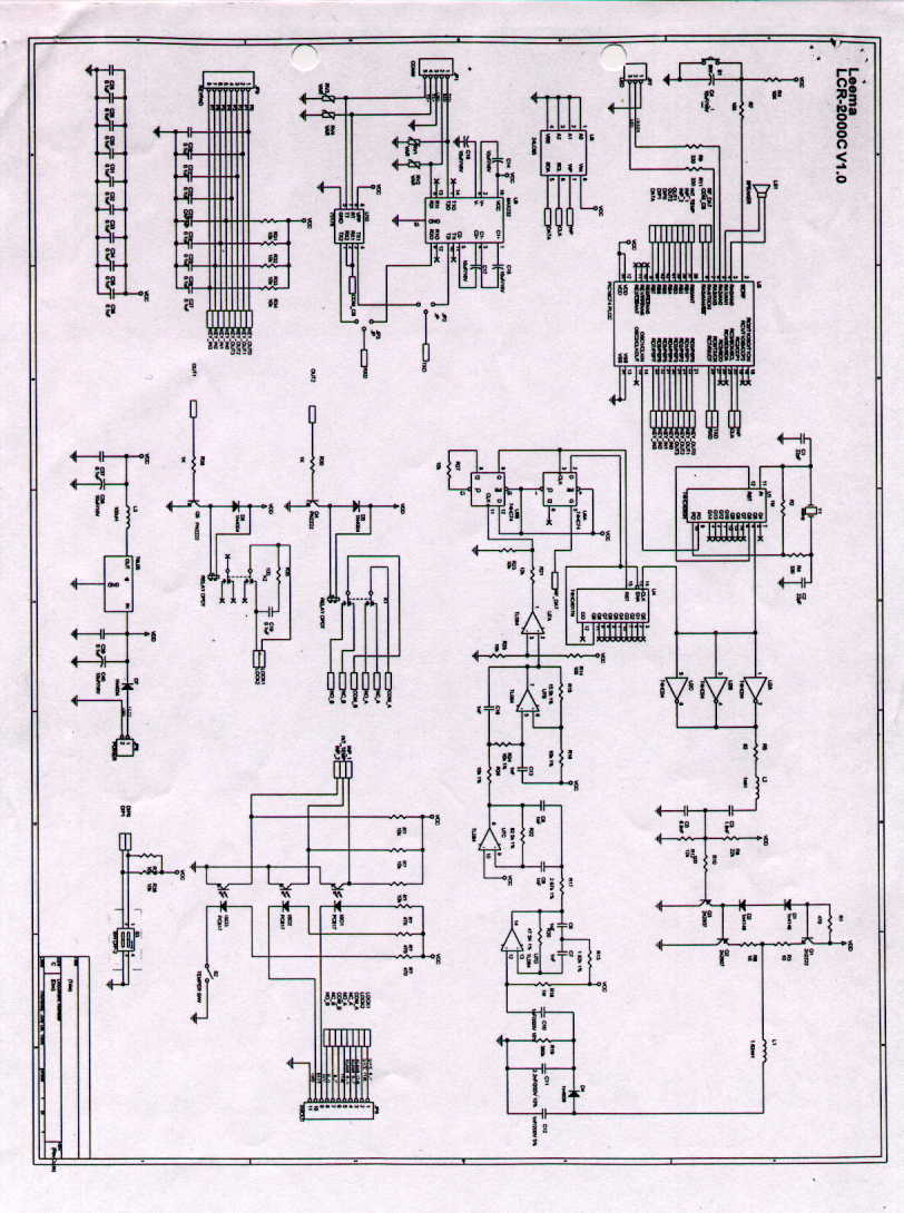
Document Text
Text extracted from the exhibit documents filed with the FCC. Open a document above to read the original.
Users Manual
10 Mbps Spread Spectrum Wireless Transceiver User Manual 2010ET User Manual Revision 1.2 Spectrum Wireless, Inc.Page 2 Notices: The information in this document is preliminary. The manufacturer assumes no responsibility for any errors that may appear in this document. Ethernet and Ethernet II are trademarks of XEROX. LANalyzer is a registered trademark of Novell, Inc. Copyright © 1998, Spectrum Wireless, Inc. All rights reserved. No part of the contents of this document may be transmitted or reproduced in any form or by any means without the written permission of Spectrum Wireless, Inc. The manufacturer assumes no responsibility for damage caused by interference due to this equipment. Regulatory Notices: NOTE: This equipment has been tested and found to comply with the limits for a Class A digital device, pursuant to Part 15 of the FCC Rules. These limits are designed to provide reasonable protection against harmful interference when the equipment is operated in a commercial environment. This equipment generates, uses, and can radiate radio frequency energy and, if not installed and used in accordance with the instruction manual, may cause harmful interference to radio communications. Operation of this equipment in a residential area is likely to cause harmful interference in which case the user will be required to correct the interference at his own expense. Pursuant to Part 15.21 of the FCC Rules, any changes or modifications to this equipment not expressly approved by Spectrum Wireless may cause harmful interference and void the FCC authorization to operate this equipment. The revision of this document is 1.2. 2010ET User Manual Revision 1.2 Spectrum Wireless, Inc.Page 3 Table of Contents 1. INTRODUCTION..................................................................................................................................... 4 1.1. WELCOME ............................................................................................................................................. 4 1.2. FEATURES OF THE 2010ET................................................................................................................ 5 2. STRUCTURE............................................................................................................................................ 6 2.1. BLOCK DIAGRAM ................................................................................................................................ 6 2.2. DESCRIPTION OF BLOCK ................................................................................................................... 7 2.3. PRINCIPLE OF OPERATION................................................................................................................ 9 2.3.1. UPLOAD PROCESS .................................................................................................................... 9 2.3.2. DOWNLOAD PROCESS............................................................................................................ 11 2.3.3. BUFFER MEMORY ................................................................................................................... 12 2.3.4. FORWARD ERROR CORRECTION (FEC)............................................................................... 13 2.3.5. RE-TRANSMISSION .................................................................................................................. 14 2.3.6. SECURITY ................................................................................................................................. 17 2.3.7. ANTENNA DIVERSITY .............................................................................................................. 18 2.3.8. ANTENNA RECOGNITION ....................................................................................................... 19 2.3.9. CHANNEL ACCESS PROTOCOL ............................................................................................. 20 3. APPEARANCE ....................................................................................................................................... 21 3.1. DIMENSIONS....................................................................................................................................... 21 3.2. FRONT AND REAR PANEL ............................................................................................................... 21 4. SPECIFICATIONS................................................................................................................................. 22 4.1. GENERAL............................................................................................................................................. 22 4.2. RADIO................................................................................................................................................... 23 4.3. NETWORK ........................................................................................................................................... 24 4.4. PORT ..................................................................................................................................................... 25 4.4.1. MAU PORT ................................................................................................................................ 25 4.4.2. DC 6.2V PORT........................................................................................................................... 27 4.5. LED DISPLAY...................................................................................................................................... 28 4.6. EMISSIONS .......................................................................................................................................... 28 4.7. ENVIRONMENTAL ............................................................................................................................. 28 4.8. CONFIGURABLE PARAM…
Text truncated - open the document above for the full version.
Users Manual
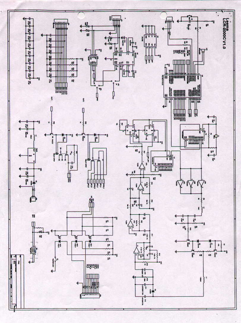
LCR-2000C Card Reader Operating Manual Leema Pharmed. Inc., The Best there is ... 1 LCR-2000C MANUAL Do not make any changes or modifications to the equipment unless otherwise specified in the manual. If such changes or modifications should be made, the manufacturer's equipment warranty will be invalidated. This equipment has been tested and found to comply with the limits for a Class “ ” device, pursuant to Part “ ” of the FCC rules. Contents 1 General Descriptions 2 Installation & Operation 2.1 Part List and Block Diagram 2.2 Installing LCR-2000 2.2.1 Installation Procedure 2.2.2 Wiring Diagram 2.2.3 Cautions 3 Features and Functions 4 Operating LCR-2000C 4.1 Basic Operation LCR-2000C Card Reader Operating Manual Leema Pharmed. Inc., The Best there is ... 2 4.1.1 Using R/F Card 4.1.2 Using Exit Button 4.1.3 Using keypad 4.2 Programming Procedure 4.2.1 Keypad Configuration 4.2.2 Functions in Program Mode 4.2.3 Mode Changing to Program Mode 4.2.4 Registering the ID 4.2.5 Deleting the ID 4.2.6 Changing Door Mode(Normal Close/ Normal Open) 4.2.7 Setting Door Open Time 4.2.8 Changing Password 4.2.9 Finishing Program Mode 4.2.10 Change your Password 4.2.11 Manual door open Password setting 4.2.12 End the Program Mode 5 Trouble Shooting 6 Quality Assurance 7 Technical Features & Specifications LCR-2000C Card Reader Operating Manual Leema Pharmed. Inc., The Best there is ... 3 1. General Descriptions The Leema identification system consist of two basic elements: reader and the contactless card(or Tag). The reader emits a low frequency electromagnetic field via it's antenna. When a transponder passes within it's range, it is energized, causing it to transmit it's ID code back to the reader. Since Leema transponders are completely powered by the reader, they are maintenance-free and require no batteries. Each transponder has unique ID-numbers, and this approach results in a tamper proof system suited to a broad variety of identification applications. LCR-2000C reader is designed to proximity type, and it provides an advanced benefit than M/S type or IC type reader. Combined with internal controller, it can be purchased more cheaply and can be applied such as office room, apt, garage and etc. as an access control device. In addition it is easy to install, and serves below benefit to users. z Reduction in the number of clerical errors in recording data. z Adopt proximity style, provides faster data collection. LCR-2000C makes use of the patented Leema technology, which optimises read distances and provides unprecedented system performance near metals and in areas with high levels of electromagnetic inter-ference(EMI). LCR-2000C Card Reader Operating Manual Leema Pharmed. Inc., The Best there is ... 4 The reader is activated simply by connecting power cable. When an attempt is made to read a transponder, the reader will continuously emit power pulses until the transponder is successfully read. The ID number of contactless card is compared with the data which is stored in the memory of the reader, and decide whether access grant or deny. If access is granted, the door is opened and one can enter the room(or site) and if not, reader generates alarm. ❍ Applications • Entry control • Personnel Administration • Parking system • Restaurant System • Logistics • Etc... LCR-2000C Card Reader Operating Manual Leema Pharmed. Inc., The Best there is ... 5 2. Installation & Operation 2.1 Part List and Block Diagram [Figure 1] Component of LCR-2000C Mounting Plate Silicon Pad pa er Housing & Keypad LCR-2000C Card Reader Operating Manual Leema Pharmed. Inc., The Best there is ... 6 [Figure 2] General Card Key System LCR-2000C Exit Button Striker Door Lock LCR-2000C Card Reader Operating Manual Leema Pharmed. Inc., The Best there is ... 7 [Figure 3] Data I/O Process of LCR-2000C LCR-2000C Card Readin R/F Data Door Alarm O/contact I/conta ct Door tt Exit Butto Contact Doo r LCR-2000C Card Reader Operating Manual Leema Pharmed. Inc., The Best there is ... 8 2.2 Installing LCR-2000C 2.2.1 Installation Procedure Each LCR-2000C device consist of four parts; a mounting plate, housing, and a reader,and a Silicon Pad. Reader is already attached to housing before it is packed. 1. Orient the mounting plate with the threaded insert at the bottom; attach it directly to the wall surface using anchor screw or toggle bolts. (Figure 4) [Figure 4] Basic Installation Procedure Cable Box Wall Surface Mounting l LCR-2000C Housing Silicon Pd LCR-2000C Card Reader Operating Manual Leema Pharmed. Inc., The Best there is ... 9 2. Pull cable ends through the access hole in the mounting plate(See the Table 1 and Table 2); a. Connect the +(R) cable to power cable. b. Connect the G(B) cable to ground. c. Connect the •(R) cable to 12VC of Door Lock, and set to Normal Close. d. Connect the •(Br) cable to another cable of Door Lock. e. Connect the •(Bl) Cable to Door Contact. f. Connect the •(P) cable to Exit Button. g. Connect the •(S) cable to COM cable of ALARM device. h. Be care the color, and short. 3. Attach the housing to mounting plate; a. Hold the bottom end of the housing away from the mounting plate. b. Insert the tab(inside top of housing) into the slots at the top of the mounting plate. c. Swing the bottom of the housing toward the mounting plate. d. Secure by installing the screw or bolt. 4. Apply power. The LED will flash once. LCR-2000C Card Reader Operating Manual Leema Pharmed. Inc., The Best there is ... 10 2.2.2 Wiring Diagram As the [Figure 6] connect the cables. Be care the colors not to be mismatched. Table 1 – I/O Port Cables DeviceCableColorDescription 1RedDoor Lock +12VDC Door Lock 2BrownDoor Lock 3ScarletAlarm, Common 4YellowAlarm, Normally Closed Alarm 5GreenAlarm, Normally Open 6ScarletCommon 7GrayNormally Closed Te mp 8WhiteNormally Open Door Contact9BlueDoor Contact 10PinkExit Button Control Exit Button 11BlackExit Button Ground LCR-2000C Card Reader Operating Manual Leema Pharmed. Inc., The Best there is ... 11 T…
Text truncated - open the document above for the full version.
External Photos
# CARD READER (EUT) TRANSMITTER: FRONT VIEW # CARD READER (EUT) TRANSMITTER: REAR VIEW # CONTACTLESS CARD (EUT) RECEIVER
External Photos
# CARD READER (EUT) TRANSMITTER: FRONT VIEW # CARD READER (EUT) TRANSMITTER: REAR VIEW # CONTACTLESS CARD (EUT) RECEIVER
ID Label/Location Info
ONETECH Corp. 2F. KUNHAN BD, 1557-11 SEOCHO-DONG, SEOCHO-KU, SEOUL 137-070 KOREA TEL: 587-9037 FAX: 587-9039 ONETECH IDENTIFICATION LABEL: PROPOSED FCC ID LABEL The label included following statement will be attached on the rear side of transmitter. This device complies with Part 15 of the FCC Rules. Operation is subject to the following two conditions: (1) this device may not cause harmful interference, and (2) this device must accept any interference received, including interference that may cause undesired operations. Made in Korea. FCC ID : N9FLCR-2000C ONETECH Corp. 2F. KUNHAN BD, 1557-11 SEOCHO-DONG, SEOCHO-KU, SEOUL 137-070 KOREA TEL: 587-9037 FAX: 587-9039 ONETECH The label included following statement will be attached on the rear side of receiver. FCC ID : N9FLCR-2000C Made in Korea
ID Label/Location Info
ONETECH Corp. 2F. KUNHAN BD, 1557-11 SEOCHO-DONG, SEOCHO-KU, SEOUL 137-070 KOREA TEL: 587-9037 FAX: 587-9039 ONETECH IDENTIFICATION LABEL: PROPOSED FCC ID LABEL The label included following statement will be attached on the rear side of transmitter. This device complies with Part 15 of the FCC Rules. Operation is subject to the following two conditions: (1) this device may not cause harmful interference, and (2) this device must accept any interference received, including interference that may cause undesired operations. Made in Korea. FCC ID : N9FLCR-2000C ONETECH Corp. 2F. KUNHAN BD, 1557-11 SEOCHO-DONG, SEOCHO-KU, SEOUL 137-070 KOREA TEL: 587-9037 FAX: 587-9039 ONETECH The label included following statement will be attached on the rear side of receiver. FCC ID : N9FLCR-2000C Made in Korea
Internal Photos
ONETECH Corp. 2F. KUNHAN BD, 1557-11 SEOCHO-DONG, SEOCHO-KU, SEOUL 137-070 KOREA TEL: 587-9037 FAX: 587-9039 ONETECH ELECTROMAGNETIC EMISSIONS COMPLIANCE REPORT PRODUCTRF CARD READER FCC IDN9FLCR-2000C MODEL NO.LCR-2000CSERIAL NO.N/A APPLICANT & ADDRESS LEEMA PHARMED. INC. 9F. LEEMA BLDG., 146-1 SUSONG-DONG CHONGRO-GU, SEOUL 110-140, KOREA REPORT NO.E98OR-004ISSUE DATEOctober 14, 1998 PREPARED BY : ONETECH CORPORATION 2 F. KUNHAN B/D, 1557-11, SEOCHO-DONG, SEOCHO-KU, SEOUL 137-070 KOREA (TEL)02-587-9037, (FAX)02-587-9039 RF CARD READER CERTIFICATION TO FCC PART 15 REQUIREMENT REPORT NO.: E98OR-004FCC ID: N9FLCR-2000C DATE: October 14, 1998 LIST OF EXHIBITS FCC ID: N9FLCR-2000C MODEL : LCR-2000C “RF CARD READER” EXHIBIT 1. IDENTIFICATION LABEL 2. AGENT AUTHORIZATION 3. MODIFICATION LIST 4. TECHNICAL INFORMATION: ELECTROMAGNETIC EMISSIONS COMPLIANCE REPORT 5. PHOTO REPORT 6. USER’S MANUAL & SCHEMATIC (BLOCK DIAGRAM) PREPARED BY:ONETECH CORP. 2 F. KUNHAN B/D, 1557-11, SEOCHO-DONG, SEOCHO-KU, SEOUL 137-070 KOREA (TEL)02-587-9037(FAX)02-587-9039 REPORT NO.: E98OR-004FCC ID: N9FLCR-2000C DATE: October 14, 1998 EXHIBIT 1. IDENTIFICATION LABEL: PROPOSED FCC LABEL (Part15 Sec. 15.19) The label included following statement will be attached on the rear side of transmitter. The label included following statement will be attached on the rear side of receiver. “Please find an ID Label for EUT at ID Label/Location Info in Exhibit Type” This device complies with Part 15 of the FCC Rules. Operation is subject to the following two conditions: (1) this device may not cause harmful interference, and (2) this device must accept any interference received, including interference that may cause undesired operations. Made in Korea. FCC ID : N9FLCR-2000C FCC ID : N9FLCR-2000C Made in Korea REPORT NO.: E98OR-004FCC ID: N9FLCR-2000C DATE: October 14, 1998 EXHIBIT 2. AGENT AUTHORIZATION: “Please find an Agent Authorization Letter at Attestation Statements in Exhibit Type” REPORT NO.: E98OR-004FCC ID: N9FLCR-2000C DATE: October 14, 1998 EXHIBIT 3. MODIFICATION LIST: “There was no modified items during EMI test” REPORT NO.: E98OR-004FCC ID: N9FLCR-2000C DATE: October 14, 1998 EXHIBIT 4. TECHNICAL INFORMATION: ELECTROMAGNETIC EMISSIONS COMPLIANCE REPORT PRODUCTRF CARD READER FCC IDN9FLCR-2000C MODEL NO.LCR-2000CSERIAL NO.N/A APPLICANT & ADDRESS LEEMA PHARMED. INC. 9F. LEEMA BLDG., 146-1 SUSONG-DONG CHONGRO-GU, SEOUL 110-140, KOREA REPORT NO.E98OR-004ISSUE DATEOctober 14, 1998 PREPARED BY : ONETECH CORPORATION 2 F. KUNHAN B/D, 1557-11, SEOCHO-DONG, SEOCHO-KU, SEOUL 137-070 KOREA (TEL)02-587-9037, (FAX)02-587-9039 RF CARD READER CERTIFICATION TO FCC PART 15 REQUIREMENT REPORT NO.: E98OR-004FCC ID: N9FLCR-2000C DATE: October 14, 1998 TABLE OF CONTENTS Page 1. VERIFICATION OF COMPLIANCE................................................................................................................. 1 2. GENERAL INFORMATION .............................................................................................................................. 2 2.1 Product Description .........................................................................................................................................................2 2.2 Related Submittal(s) / Grant(s)........................................................................................................................................2 2.3 Test System Details .........................................................................................................................................................3 2.4 Test Methodology............................................................................................................................................................3 2.5 Test Facility.....................................................................................................................................................................3 3. SYSTEM TEST CONFIGURATION ................................................................................................................. 4 3.1 Justification .....................................................................................................................................................................4 3.2 Equipment Modifications ................................................................................................................................................4 3.3 Operating Conditions. .....................................................................................................................................................4 3.4 Cable Description and Noise Suppression Parts on Cable ..............................................................................................4 .3.4 Configuration of Test System.........................................................................................................................................5 4. PRELIMINARY TESTS ..................................................................................................................................... 6 4.1 AC Power line Conducted Emissions Tests ....................................................................................................................6 4.2 Radiated Emissions Tests ................................................................................................................................................6 5. CONDUCTED AND RADIATED MEASUREMENT PHOTOS ...................................................................... 7 6. FINAL RESULT OF MEASUREMENT ............................................................................................................ 9 6.1 Conducted Emissions Tests .............................................................................................................................................9 6.2 Radiated Emission Test ............................................................................…
Text truncated - open the document above for the full version.
Test Report
ONETECH Corp. 2F. KUNHAN BD, 1557-11 SEOCHO-DONG, SEOCHO-KU, SEOUL 137-070 KOREA TEL: 587-9037 FAX: 587-9039 ONETECH ELECTROMAGNETIC EMISSIONS COMPLIANCE REPORT PRODUCTRF CARD READER FCC IDN9FLCR-2000C MODEL NO.LCR-2000CSERIAL NO.N/A APPLICANT & ADDRESS LEEMA PHARMED. INC. 9F. LEEMA BLDG., 146-1 SUSONG-DONG CHONGRO-GU, SEOUL 110-140, KOREA REPORT NO.E98OR-004ISSUE DATEOctober 14, 1998 PREPARED BY : ONETECH CORPORATION 2 F. KUNHAN B/D, 1557-11, SEOCHO-DONG, SEOCHO-KU, SEOUL 137-070 KOREA (TEL)02-587-9037, (FAX)02-587-9039 RF CARD READER CERTIFICATION TO FCC PART 15 REQUIREMENT REPORT NO.: E98OR-004FCC ID: N9FLCR-2000C DATE: October 14, 1998 LIST OF EXHIBITS FCC ID: N9FLCR-2000C MODEL : LCR-2000C “RF CARD READER” EXHIBIT 1. IDENTIFICATION LABEL 2. AGENT AUTHORIZATION 3. MODIFICATION LIST 4. TECHNICAL INFORMATION: ELECTROMAGNETIC EMISSIONS COMPLIANCE REPORT 5. PHOTO REPORT 6. USER’S MANUAL & SCHEMATIC (BLOCK DIAGRAM) PREPARED BY:ONETECH CORP. 2 F. KUNHAN B/D, 1557-11, SEOCHO-DONG, SEOCHO-KU, SEOUL 137-070 KOREA (TEL)02-587-9037(FAX)02-587-9039 REPORT NO.: E98OR-004FCC ID: N9FLCR-2000C DATE: October 14, 1998 EXHIBIT 1. IDENTIFICATION LABEL: PROPOSED FCC LABEL (Part15 Sec. 15.19) The label included following statement will be attached on the rear side of transmitter. The label included following statement will be attached on the rear side of receiver. “Please find an ID Label for EUT at ID Label/Location Info in Exhibit Type” This device complies with Part 15 of the FCC Rules. Operation is subject to the following two conditions: (1) this device may not cause harmful interference, and (2) this device must accept any interference received, including interference that may cause undesired operations. Made in Korea. FCC ID : N9FLCR-2000C FCC ID : N9FLCR-2000C Made in Korea REPORT NO.: E98OR-004FCC ID: N9FLCR-2000C DATE: October 14, 1998 EXHIBIT 2. AGENT AUTHORIZATION: “Please find an Agent Authorization Letter at Attestation Statements in Exhibit Type” REPORT NO.: E98OR-004FCC ID: N9FLCR-2000C DATE: October 14, 1998 EXHIBIT 3. MODIFICATION LIST: “There was no modified items during EMI test” REPORT NO.: E98OR-004FCC ID: N9FLCR-2000C DATE: October 14, 1998 EXHIBIT 4. TECHNICAL INFORMATION: ELECTROMAGNETIC EMISSIONS COMPLIANCE REPORT PRODUCTRF CARD READER FCC IDN9FLCR-2000C MODEL NO.LCR-2000CSERIAL NO.N/A APPLICANT & ADDRESS LEEMA PHARMED. INC. 9F. LEEMA BLDG., 146-1 SUSONG-DONG CHONGRO-GU, SEOUL 110-140, KOREA REPORT NO.E98OR-004ISSUE DATEOctober 14, 1998 PREPARED BY : ONETECH CORPORATION 2 F. KUNHAN B/D, 1557-11, SEOCHO-DONG, SEOCHO-KU, SEOUL 137-070 KOREA (TEL)02-587-9037, (FAX)02-587-9039 RF CARD READER CERTIFICATION TO FCC PART 15 REQUIREMENT REPORT NO.: E98OR-004FCC ID: N9FLCR-2000C DATE: October 14, 1998 TABLE OF CONTENTS Page 1. VERIFICATION OF COMPLIANCE................................................................................................................. 1 2. GENERAL INFORMATION .............................................................................................................................. 2 2.1 Product Description .........................................................................................................................................................2 2.2 Related Submittal(s) / Grant(s)........................................................................................................................................2 2.3 Test System Details .........................................................................................................................................................3 2.4 Test Methodology............................................................................................................................................................3 2.5 Test Facility.....................................................................................................................................................................3 3. SYSTEM TEST CONFIGURATION ................................................................................................................. 4 3.1 Justification .....................................................................................................................................................................4 3.2 Equipment Modifications ................................................................................................................................................4 3.3 Operating Conditions. .....................................................................................................................................................4 3.4 Cable Description and Noise Suppression Parts on Cable ..............................................................................................4 .3.4 Configuration of Test System.........................................................................................................................................5 4. PRELIMINARY TESTS ..................................................................................................................................... 6 4.1 AC Power line Conducted Emissions Tests ....................................................................................................................6 4.2 Radiated Emissions Tests ................................................................................................................................................6 5. CONDUCTED AND RADIATED MEASUREMENT PHOTOS ...................................................................... 7 6. FINAL RESULT OF MEASUREMENT ............................................................................................................ 9 6.1 Conducted Emissions Tests .............................................................................................................................................9 6.2 Radiated Emission Test ............................................................................…
Text truncated - open the document above for the full version.
Test Report
ONETECH Corp. 2F. KUNHAN BD, 1557-11 SEOCHO-DONG, SEOCHO-KU, SEOUL 137-070 KOREA TEL: 587-9037 FAX: 587-9039 ONETECH ELECTROMAGNETIC EMISSIONS COMPLIANCE REPORT PRODUCTRF CARD READER FCC IDN9FLCR-2000C MODEL NO.LCR-2000CSERIAL NO.N/A APPLICANT & ADDRESS LEEMA PHARMED. INC. 9F. LEEMA BLDG., 146-1 SUSONG-DONG CHONGRO-GU, SEOUL 110-140, KOREA REPORT NO.E98OR-004ISSUE DATEOctober 14, 1998 PREPARED BY : ONETECH CORPORATION 2 F. KUNHAN B/D, 1557-11, SEOCHO-DONG, SEOCHO-KU, SEOUL 137-070 KOREA (TEL)02-587-9037, (FAX)02-587-9039 RF CARD READER CERTIFICATION TO FCC PART 15 REQUIREMENT REPORT NO.: E98OR-004FCC ID: N9FLCR-2000C DATE: October 14, 1998 LIST OF EXHIBITS FCC ID: N9FLCR-2000C MODEL : LCR-2000C “RF CARD READER” EXHIBIT 1. IDENTIFICATION LABEL 2. AGENT AUTHORIZATION 3. MODIFICATION LIST 4. TECHNICAL INFORMATION: ELECTROMAGNETIC EMISSIONS COMPLIANCE REPORT 5. PHOTO REPORT 6. USER’S MANUAL & SCHEMATIC (BLOCK DIAGRAM) PREPARED BY:ONETECH CORP. 2 F. KUNHAN B/D, 1557-11, SEOCHO-DONG, SEOCHO-KU, SEOUL 137-070 KOREA (TEL)02-587-9037(FAX)02-587-9039 REPORT NO.: E98OR-004FCC ID: N9FLCR-2000C DATE: October 14, 1998 EXHIBIT 1. IDENTIFICATION LABEL: PROPOSED FCC LABEL (Part15 Sec. 15.19) The label included following statement will be attached on the rear side of transmitter. The label included following statement will be attached on the rear side of receiver. “Please find an ID Label for EUT at ID Label/Location Info in Exhibit Type” This device complies with Part 15 of the FCC Rules. Operation is subject to the following two conditions: (1) this device may not cause harmful interference, and (2) this device must accept any interference received, including interference that may cause undesired operations. Made in Korea. FCC ID : N9FLCR-2000C FCC ID : N9FLCR-2000C Made in Korea REPORT NO.: E98OR-004FCC ID: N9FLCR-2000C DATE: October 14, 1998 EXHIBIT 2. AGENT AUTHORIZATION: “Please find an Agent Authorization Letter at Attestation Statements in Exhibit Type” REPORT NO.: E98OR-004FCC ID: N9FLCR-2000C DATE: October 14, 1998 EXHIBIT 3. MODIFICATION LIST: “There was no modified items during EMI test” REPORT NO.: E98OR-004FCC ID: N9FLCR-2000C DATE: October 14, 1998 EXHIBIT 4. TECHNICAL INFORMATION: ELECTROMAGNETIC EMISSIONS COMPLIANCE REPORT PRODUCTRF CARD READER FCC IDN9FLCR-2000C MODEL NO.LCR-2000CSERIAL NO.N/A APPLICANT & ADDRESS LEEMA PHARMED. INC. 9F. LEEMA BLDG., 146-1 SUSONG-DONG CHONGRO-GU, SEOUL 110-140, KOREA REPORT NO.E98OR-004ISSUE DATEOctober 14, 1998 PREPARED BY : ONETECH CORPORATION 2 F. KUNHAN B/D, 1557-11, SEOCHO-DONG, SEOCHO-KU, SEOUL 137-070 KOREA (TEL)02-587-9037, (FAX)02-587-9039 RF CARD READER CERTIFICATION TO FCC PART 15 REQUIREMENT REPORT NO.: E98OR-004FCC ID: N9FLCR-2000C DATE: October 14, 1998 TABLE OF CONTENTS Page 1. VERIFICATION OF COMPLIANCE................................................................................................................. 1 2. GENERAL INFORMATION .............................................................................................................................. 2 2.1 Product Description .........................................................................................................................................................2 2.2 Related Submittal(s) / Grant(s)........................................................................................................................................2 2.3 Test System Details .........................................................................................................................................................3 2.4 Test Methodology............................................................................................................................................................3 2.5 Test Facility.....................................................................................................................................................................3 3. SYSTEM TEST CONFIGURATION ................................................................................................................. 4 3.1 Justification ...............................…
Text truncated - open the document above for the full version.
Contact Information
Applicant
JUNG-HUN YANG(SYSTEM DIVISION ENGINEER)
+82-2-734-3311Fax: +82-2-725-0721
Technical Contact
ONETECH CORPORATIONYONG-KWANG KWON
[email protected]+82-2-347-765-8289
426-1 DAESSANGRYUNG-RI, CHOWOL-MYUN, KWANGJU-KUN · KYUNGGI-DO · South Korea
Non-Technical Contact
ONETECH CORPORATIONI.C. KIM
[email protected]+82-2-587-9037
Test Firm
Onetech CorporationIhn-Cheol Kim
- -
Technical Specifications
| # | Rule Parts | Frequency Range | Power Output |
|---|---|---|---|
| 1 | 15C | 0.125 MHz - 0.125 MHz | - |