N9MSC2000Scanter 2000 Series Radar Transceiver for VTS, CS, and SRS (Naval)
Terma A/S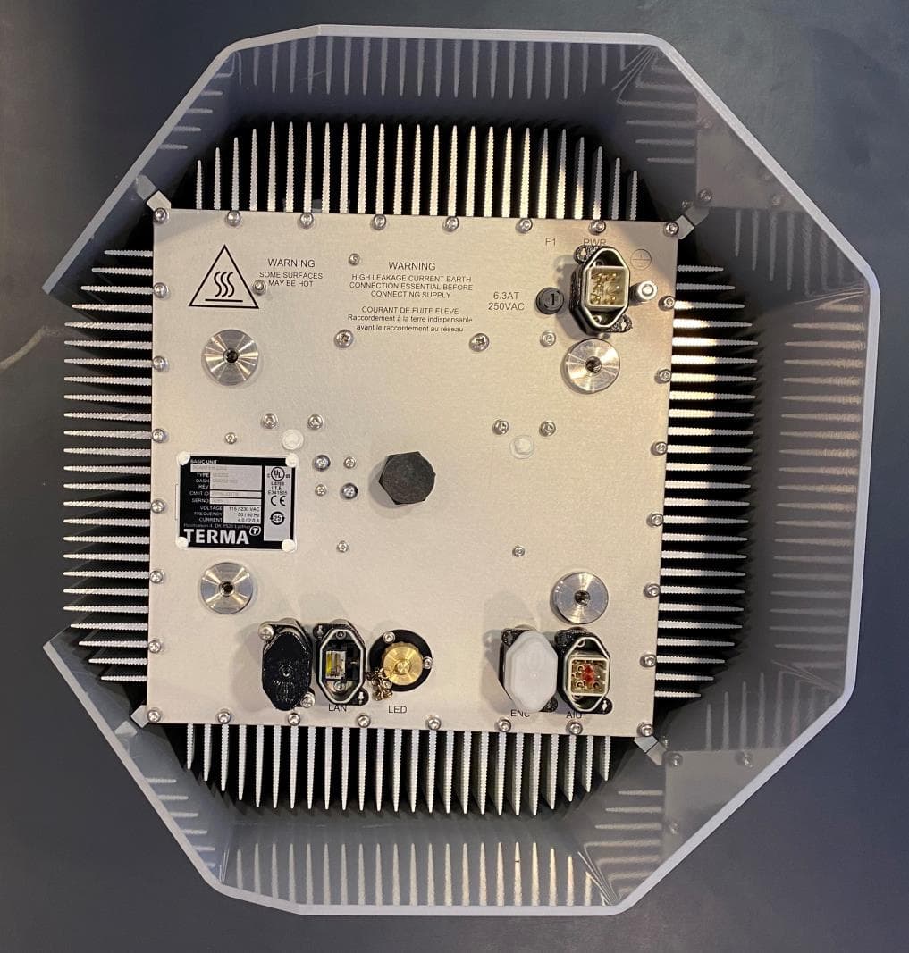
Click to zoom
Application Details
- Equipment Class
- TNB - Licensed Non-Broadcast Station Transmitter
- Date of Grant
- Jun 27, 2021
- Application Purpose
- Original Equipment
- Date of Application
- Jun 27, 2021
- Equipment Note
- Scanter 2000 Series Radar Transceiver for VTS, CS, and SRS (Naval)
- Frequency Range
- 9300.00000000 - 9500.00000000
- Company
- Terma A/S
- Country
- Denmark
Documents & Files
Document Text
Text extracted from the exhibit documents filed with the FCC. Open a document above to read the original.
Attestation Statements
21 April2021 TIMCO Engineering, lnc. 849 NW State Road 45 Newberry, FL 32669 Cc Your ref N9MSC2000 Our ref 2005000-QQ Certification of FCG lD: N9MSG2000 - SDoC Attestation Statement To Whom lt May Concern: ln support of the subject Certification, the undersigned, on behalf of Applicant Terma A/S, attests to the fact that Terma fuS will apply the Supplier's Declaration of Conformity procedure to the class B computer peripheral portion of this filing. Please do not hesitate to contact us if you need any additional information. Terma North America lnc. dottie. hersey@termana. com 571-228-5179 TERMA@ Terma North America lnc. 2461 South Clark Street Cenlury Two, Suite 810 Arlington, VA22202 USA T+1 (703)4129410 F+1 (703)4129415 [email protected] www.terma.com
Attestation Statements
13 Apnl2021 Federal Communications Commission Authorization and Evaluation Division 7435 Oakland Mills Road Columbia, MD 21046 USA Cc Your ref N9MSC2000 Our ref 2005000-QP REF: FGG lD: N9MSC2000 Dear Sir/Madam: This equipment meets the requirements of the FCC Rules, Part 90.203(e) and (g), as applicable. Programming of this product's transmit frequencies can be performed ONLY by the manufacturer, authorized service and maintenance personnel. The operator cannot program transmit ftequencies using the equipment's extemal operating controls. Yours sincerely, Terma North America lnc. TERMA@
Cover Letter(s)
13 April2021 TIMCO ENGINEERING, INC. 849 N.W. State Road 45 P.O. Box 370 Newberry, FL 32669 Cc Your ref: P3453 Our ref: 2005000-QB Subject: Application(s) for Certification for FCC lD NgMSC2000 and lC:26284- sc2000 To Whom lt May Concern: We, the undersigned, hereby authorize Sharon Hoffman at TIMCO ENGINEERING, lNC. on our behalf, to apply for certification on our equipment referenced above. Any and all acts carried out by TIMCO ENGINEERING, lNC. on our behalf shall have the same effect as acts of our own. This is to advise that we are in full compliance with the Anti-Drug Abuse Act. We, the applicant, are not subject to a denial of federal benefits pursuant to Section 5301 of the Anti-Drug Act of 1988, 21 USC853a, and no party to the application is subject to a denial of federal benefits pursuant to that section. Yours sincerely, Tema North America lnc. dottie. [email protected] TERMA@ Terma North America lnc, 2461 South Clark Street Century Two, Suite 810 Adington, V422202 USA T +1 (703) 412 9410 F +1 (703\4129415 [email protected] www.terma.com
Cover Letter(s)
21 April 2021 Federal Communications Commission Authorization and Evaluation Division 445 12th Street, SW Washington, DC 20554 Your ref: Our ref: N9MSC2000 2005000-QH Subject: Confidentiality Request Regarding Application For Certification of FCC ID: N9MSC2000 To Whom It May Concern: TERMA ® Terma North America Inc. 2461 South Clark Street Century Two, Suite 810 Arlington, VA 22202 USA T +1 (703) 412 9410 F +1 (703) 412 9415 [email protected] www.terma.com Pursuant to Sections 0.457 and 0.459 of the Commission's Rules, we hereby request permanent confidential treatment of information accompanying this application as outlined below: •Block Diagram (Terma doc. N9MSC2000_Block_Diagram_2005000-QE) •Sc hematics (Terma doc. N9MSC2000_Schematics_2005000-QD) •I nternal Photos (Terma doc. N9MSC2000_Internal_Photos_2005000-QG) •Parts List (Terma doc. N9MSC2000_Parts_List_2005000-QF) •Circuit Description (Terma doc. N9MSC2000_Circuit_Description_2005000-QE) •Tuning Procedure (Terma doc. N9MSC2000_ Tuning_Procedure_902000-TF) •Manuals (Terma doc. N9MSC2000_User's_Manual_902200-HT, N9MSC2000_ User's_Manual_ 902200-HC, N9MSC2000 _ User's _Manual_ 902602-HT) •N9MSC2000_Operating_the_Radar_Transceiver_200500-QN-A.pdf This Confidentiality Request to restrict access to equipment and documentation is to inform TIMCO that access to equipment and related documentation supplied by Terma is to be restricted to only authorized users to ensure the security of the equipment and confidentiality of related documentation at all times. Only designated professionals shall be allowed to maintain or service the equipment. Terma is requesting the internal photos be permanently confidential. This non-consumer device is inaccessible to the general public and shall be kept in a secured and locked environment. The reason for this request is that the Documents are of a technical nature and are not provided to the consumer because the consumer cannot service the device. Our products will be sold to a limited audience and Terma wishes the Documents to be inaccessible to the general public at all times. Our ref: 2005000-QH Appropriate documentation will be made be available only to Terma partners and integrators. Designated professionals under the employ of these partners and integrators will be responsible for service and maintenance of our products. Each partner and integrator will be under a non-disclosure agreement with Terma. The above materials contain trade secrets and proprietary information not customarily released to the public. The public disclosure of these materials may be harmful to the applicant and provide unjustified benefits to its competitors. The applicant understands that pursuant to Section 0.457 of the Rules, disclosure of this application and all accompanying documentation will not be made before the date of the Grant for this application. Pursuant to DA04-1705 June 15, 2004 of the Commission's public notice, we also request temporary confidential treatment of information accompanying this application for ninety (90) days as outlined below: • External Photos (Terma doc. N9MSC2000_External_Photos_2005000-QR) • Test Setup Photos Yours sincerely, 1.� k !.�y � General Counsel and Corporate Secretary Terma North America Inc. [email protected] 2/2 (j)
External Photos
SCANTER 2202 TERMA DOCUMENT: 2005000-QR REV. A EXTERNALPHOTOS APPLICANT: TERMA A/S FCC ID: N9MSC2000 IC: 2628A-SC2000 APRIL 2021 © The Terma Group 2021 Transceiver_902202-002_Rev. D_Front © The Terma Group 2021 Transceiver_902202-002_Rev. D_Rear © The Terma Group 2021 Transceiver_902202-002_Rev. D_Top © The Terma Group 2021 Transceiver_902202-002_Rev. D_Top_W/O Sun cover © The Terma Group 2021 Transceiver_902202-002_Rev. D_Bottom © The Terma Group 2021 Transceiver_902202-002_Rev. D_IdentificationPlate
ID Label/Location Info
Page 1 of 2 Nameplate examples: Rev. A serial number 3001 SCANTER 2602 example SCANTER 2202 example BASIC UNIT H ovmarken 4 D K 8520 Lyst rup FCC ID N9MSC5000 50/60 Hz 4.0/2.0 A 115/230 VAC REV DASH CMIIT ID SERNO CURRENT FREQUENCY VOLTAGE IC: 2628A-SC5000 IC: 2628A-SC2000 FCC ID N9MSC2000 LISTED I.T.E. 4EV9 TYPE SCANTER 2202 902202 902202-002 A 2016LJ3878 3001 SCANTER 2202 BASIC UNIT H ovmarken 4 D K 8520 Lyst rup FCC ID N9MSC5000 50/60 Hz 4.0/2.0 A 115/230 VAC REV DASH CMIIT ID SERNO CURRENT FREQUENCY VOLTAGE IC: 2628A-SC5000 IC: 2628A-SC2000 FCC ID N9MSC2000 LISTED I.T.E. 4EV9 TYPE SCANTER 2202 902202 902202-002 A 2016LJ3878 3001 SCANTER 2202 BASIC UNIT H ovmarken 4 D K 8520 Lyst rup FCC ID N9MSC5000 50/60 Hz 4.0/2.0 A 115/230 VAC REV DASH SERNO CURRENT FREQUENCY VOLTAGE IC: 2628A-SC5000 IC: 2628A-SC2000 FCC ID N9MSC2000 LISTED I.T.E. 4EV9 TYPE SCANTER 2602 902602 902602-001 A 3001 SCANTER 2602 BASIC UNIT H ovmarken 4 D K 8520 Lyst rup FCC ID N9MSC5000 50/60 Hz 4.0/2.0 A 115/230 VAC REV DASH SERNO CURRENT FREQUENCY VOLTAGE IC: 2628A-SC5000 IC: 2628A-SC2000 FCC ID N9MSC2000 LISTED I.T.E. 4EV9 TYPE SCANTER 2602 902602 902602-001 A 3001 SCANTER 2602 Terma A/S Hovmarken 4 8520 Lystrup Denm ark T +45 8743 6000 F +45 8743 6001 [email protected] www.terma.com Marking for SCANTER 2202 and 2602Title: Document: FCC ID: Date: 2005000-QL N9MSC2000 2021-04-22 Revision:A Class:DRW EID:R0567 IC Canada:2628A-SC2000 Marking for SCANTER 2202 and 2602Title: Document: FCC ID: Date: 2005000-QL N9MSC2000 2021-04-22 Revision:A Class:DRW EID:R0567 IC Canada:2628A-SC2000 Terma A/S Hovmarken 4 8520 Lystrup Denm ark T +45 8743 6000 F +45 8743 6001 [email protected] www.terma.com Marking for SCANTER 2202 and 2602Title: Document: FCC ID: Date: 2005000-QL N9MSC2000 2021-04-22 Revision:A Class:DRW EID:R0567 IC Canada:2628A-SC2000 Page 2 of 2 Nameplate position at the bottom of the transceiver Terma A/S Hovmarken 4 8520 Lystrup Denm ark T +45 8743 6000 F +45 8743 6001 [email protected] www.terma.com Marking for SCANTER 2202 and 2602Title: Document: FCC ID: Date: 2005000-QL N9MSC2000 2021-04-22 Revision:A Class:DRW EID:R0567 IC Canada:2628A-SC2000 Marking for SCANTER 2202 and 2602Title: Document: FCC ID: Date: 2005000-QL N9MSC2000 2021-04-22 Revision:A Class:DRW EID:R0567 IC Canada:2628A-SC2000 Terma A/S Hovmarken 4 8520 Lystrup Denm ark T +45 8743 6000 F +45 8743 6001 [email protected] www.terma.com Marking for SCANTER 2202 and 2602Title: Document: FCC ID: Date: 2005000-QL N9MSC2000 2021-04-22 Revision:A Class:DRW EID:R0567 IC Canada:2628A-SC2000
RF Exposure Info
Class: NTE Doc. no.: 2005000-QO Rev.: A CAGE code: R0567 FCC Calculated Safety Distances for Human Exposure for SCANTER 2000 Series Page 1 of 9 FCC ID: N9MSC2000 FCC Calculated Safety Distances for Human Exposure for SCANTER 2000 Series Doc. no.: 2005000-QO, Rev.: A Page 2 of 9 Record of Changes ECO Description Rev Date Released A See front page FCC Calculated Safety Distances for Human Exposure for SCANTER 2000 Series Doc. no.: 2005000-QO, Rev.: A Page 3 of 9 Contents 1 Introduction ...................................................................................................... 4 1.1 Purpose ............................................................................................................. 4 1.2 Scope ................................................................................................................ 4 1.3 Application ......................................................................................................... 4 2 References ....................................................................................................... 4 3 Definitions ........................................................................................................ 4 4 Calculations ..................................................................................................... 5 4.1 Preface .............................................................................................................. 5 4.2 Equations used for calculations ......................................................................... 5 5 Conclusion ....................................................................................................... 8 FCC Calculated Safety Distances for Human Exposure for SCANTER 2000 Series Doc. no.: 2005000-QO, Rev.: A Page 4 of 9 1 Introduction 1.1 Purpose The purpose of this document is to substantiate that the safety distances calculated in TERMA document number 924000-RC [1] are sufficient to comply with the FCC Guidelines for human exposure to electromagnetic fields. 1.2 Scope FCC Guidelines for Human Exposure to Radiofrequency Electromagnetic Fields applied to TERMA Radar systems. 1.3 Application Certification of SCANTER 2202 and 2602 Series radar transceivers. Certification is limited to configuration with an 80 W peak power output. Equipment to be certified: Commercial Name Terma Part Number Application SCANTER 2202 902202-xxx VTS, CS, OLC/ADLS SCANTER 2602 902602-xxx Naval 2 References Ref. Title [1] Terma document number 924000-RC Rev H, “Power Density in Proximity to SCANTER Antennas with SCANTER 4000/5000/6000 Series Transceivers” [2] “ICNIRP. Guidelines for limiting exposure to electromagnetic fields (100 kHz to 300 GHz)”. Health Phys 118(5):483-524; 2020. [3] “Evaluating Compliance with FCC Guidelines for Human Exposure to Radiofrequency Electromagnetic Fields”, OET Bulletin 65, Edition 97-01, August 1997 [4] Code of Federal Regulations (CFR): Title 47. Telecommunication § 1.1310 3 Definitions Term Definition CFR Code of Federal Regulations CS Coastal Surveillance ADLS Aircraft Detection Lighting System FCC Federal Communications Commission ICNIRP International Commission on Non-Ionizing Radiation Protection MPE Maximum Permissible Exposure OET Office of Engineering and Technology FCC Calculated Safety Distances for Human Exposure for SCANTER 2000 Series Doc. no.: 2005000-QO, Rev.: A Page 5 of 9 Term Definition OLC Obstruction Light Control VTS Vessel Traffic Services 4 Calculations 4.1 Preface In TERMA document 924000-RC, the safety distances for all combinations of SCANTER 2202/2602 radar systems and antennas from TERMA is given to be a minimum of 5 meters in the horizontal plane and/or +/- 1 meter in the vertical plane. Distances exceeding these will result in exposure below the recommended maximum limit of 10 W/m 2 given by ICNIRP [2]. In the following, the safety distances are assessed according to the methods of OET Bulletin 65 [3], showing that using the approximate formulas of OET-65 at a distance of 5 meters results in power densities below the FCC limits [4]. All the SCANTER 2202/2602 series radar systems can be configured to operate within the frequency band of 9.0 to 9.5 GHz. The maximum permissible exposure (MPE) limit at this frequency band is 1.0 mW/cm 2 = 10 W/m 2 averaged over a time period of 30 minutes according to CFR 47 § 1.1310 [4]. The antennas used are all aperture horn antennas with continuous mechanical rotation in the horizontal plane. The rotation rate is between 6 and 60 revolutions per minute, i.e. at least 180 rotations during a 30 minutes interval. Significant human exposure to radio frequency fields from the radar system is limited to the period in which the beam sweeps past a person, hence the mechanical rotation will reduce the average exposure over a 30 minutes interval. The reduction in exposure due to the rotation of the antenna is an inherent property of the radar system as described in OET Bulletin 65 [3] page 74. In the following, this will be referred to as an antenna duty cycle, since the effect is similar to that of a duty cycle in a transmitter. 4.2 Equations used for calculations In the following, the equations from OET-65 are used to find the time-averaged near-field power density for a system consisting of a SCANTER 2602 transceiver with a 7’ Compact antenna with fan-beam elevation pattern. The smallest physical antenna is chosen, as this results in the highest power density at short range. The transceiver parameters are given in Table 5-1, and the antenna parameters are given in Table 5-2. The extent of the near-field region can be calculated using equation (12) from OET Bulletin 65, page 27 푅 푁퐹 = 퐷 2 4휆 The length of the antenna (D) is 2.16 meters, the wavelength at the lowest frequency of interest (9.0GHz) is 0.0333 meters and the extent of the near-field range is 푅 푁퐹 = (2.16 푚) 2 4×0.0333 푚 =35.0 푚 FCC Calculated Safety Distances for Human Exposure for SCANTER 2000 Series Doc. no.: 2…
Text truncated - open the document above for the full version.
Test Report
Test Report # TR_1884-21_FCC_PT80-90_1 Revision: 1 Issue Date: May 6, 2021 Final Test Date: May 5, 2021 An IIA Company Test Report - FCC PARTS 80 (MRD) & 90 (TNB) Prepared For: Terma A/S Approved for Release By: Signature: Name & Title: Bruno Clavier, General Manager Date of Signature (YYYY-MM-DD): 2021-05-06 This test report shall not be reproduced except in full without the written and signed permission of Timco Engineering Inc. (IIA). This test report relates only to the items tested as identified and is not valid for any subsequent changes or modifications made to the equipment under test. Timco Engineering, Inc., an IIA Company 849 NW State Road 45, Newberry, Florida 32669 (352) 472-5500 / [email protected] Page 2 of 59 This test report shall not be reproduced except in full without the written and signed permission of Timco Engineering Inc. (IIA). Table of Contents 1. CUSTOMER INFORMATION ........................................................................................................................................................................... 4 1.1 PART 80 TEST RESULT SUMMARY ............................................................................................................................................................................4 1.2 PART 90 TEST RESULT SUMMARY ............................................................................................................................................................................ 5 2. LOCATION OF TESTING ................................................................................................................................................................................. 6 2.1 TEST LABORATORY .................................................................................................................................................................................................... 6 2.2 TESTING WAS PERFORMED, REVIEWED BY ................................................................................................................................................................ 6 3. TEST SAMPLE(S) (EUT/DUT) ........................................................................................................................................................................... 7 3.1 DESCRIPTION OF THE EUT ........................................................................................................................................................................................ 7 3.2 CONFIGURATION OF EUT ......................................................................................................................................................................................... 8 3.3 TEST SETUP OF EUT .................................................................................................................................................................................................. 8 4. TEST METHODS & APPLICABLE REGULATORY LIMITS ............................................................................................................................ 9 4.1 TEST METHODS/STANDARDS/GUIDANCE: ............................................................................................................................................................... 9 4.2 APPLIED LIMITS AND REGULATORY LIMITS: .............................................................................................................................................................. 9 5. MEASUREMENT UNCERTAINTY .................................................................................................................................................................... 9 6. ENVIRONMENTAL CONDITIONS ................................................................................................................................................................. 9 6.1 TEMPERATURE & HUMIDITY ...................................................................................................................................................................................... 9 7. LIST OF TEST EQUIPMENT AND TEST FACILITY ...................................................................................................................................... 10 7.1 LIST OF TEST EQUIPMENT ....................................................................................................................................................................................... 10 8. TEST RESULTS .................................................................................................................................................................................................. 11 8.1 POWER AT THE FINAL AMPLIFIER ............................................................................................................................................................................ 12 8.2 RF OUTPUT POWER ................................................................................................................................................................................................ 13 8.3 BANDWIDTH & EMISSION ....................................................................................................................................................................................... 14 8.3.1 Bandwidth Plot, 99%, 9384.7 MHz, 6nm ......................................................................................................................................... 15 8.3.2 Bandwidth Plot, 99%, 9384.7 MHz, 24nm....................................................................................................................................... 16 8.3.3 Bandwidth Plot, 99%, 9384.7 MHz, NAV12 nm ............................................................................................................................. 17 8.3.1 Bandwidth Plot, 99%, 9384.7 MHz, NAV24nm ..................…
Text truncated - open the document above for the full version.
Test Setup Photos
ANNEX B – Test Setup Photograph Exhibit Terma North America Inc. FCC ID: N9MSC2000 IC: 2628A-SC2000 Conducted Test Setup Radiated Testing, Below 1 GHz Radiated Testing, Above 1 GHz Radiated Testing, Above 1 GHz #2
Contact Information
Applicant
Dorothy S Hersey(Counsel and Corporate Secretary)
Test Firm
Timco Engineering, Inc.Bruno Clavier
Technical Specifications
| # | Rule Parts | Frequency Range | Power Output | Emission | Tolerance |
|---|---|---|---|---|---|
| 1 | 90 | 9.30 GHz - 9.50 GHz | 10.74 W | 200MV7N | 396.0000000000 ppm |
Other Applications from Terma A/S
N9MSC5202
Jan 10, 2021Air and Surface Surveillance Radar
Equipment Class
TNB - Licensed Non-Broadcast Station TransmitterN9MED5200
Jun 20, 1999RADAR
Equipment Class
TNB - Licensed Non-Broadcast Station Transmitter