Text extracted from the exhibit documents filed with the FCC. Open a document above to read the original.
Reunion CTR 2400 Outdoor Microwave Transceiver Installation Guide Release 1.1 July 1998 411-1333-201 Reunion CTR 2400 Outdoor Microwave Transceiver Installation Guide Document number: 411-1333-201 Product release: Release 1.1 Document version: Preliminary Date: July 1998 Copyright Country of printing Confidentiality Legal statements Trademarks 1998 Northern Telecom Northern Telecom Ltd., all rights reserved Printed in Canada NORTHERN TELECOM CONFIDENTIAL: The information contained in this document is the property of Northern Telecom. Except as specifically authorized in writing by Northern Telecom, the holder of this document shall keep the information contained herein confidential and shall protect same in whole or in part from disclosure and dissemination to third parties and use same for evaluation, operation, and maintenance purposes only. Information is subject to change without notice. REUNION TM is a trademark of Northern Telecom Ltd. v Reunion CTR 2400 Installation Guide Publication history July 1998 •Initial preliminary release of the document vi 411-1333-201 Preliminary July 1998 vii Reunion CTR 2400 Installation Guide About this guide Purpose This guide provides the information required to install and operate the CTR 2400 outdoor microwave transceiver. The CTR 2400 is one of the Radio Frequency (RF) products that constitute a Nortel Reunion TM product line. The associated products include the following types of cell site equipment: •broadband transmitters •broadband receivers •broadband repeaters •broadband transceivers Audience The audience for this document are those who install and operate the CTR 2400. To take full advantage of this guide, you should have a basic understanding of microwave fundamentals and know how to use microwave test equipment. viii 411-1333-201 Preliminary July 1998 Organization This Guide is divided into seven sections: •Product Overview describes the CTR’s components and theory of operation. •Pre-Instalation describes the basics of handling the equipment upon arrival. •Reunion Safety Standards provide a quick review of general safety guidelines. •Installing the CTR 2400 explains how to physically install the transceiver. •CTR 2400 Maintenance describes basic maintenance procedures to ensure that the transceiver is operating correctly. •CTR 2400 Diagnostic Reference Chart provides a quick troubleshooting guide. •List of terms provides a quick reference to terms and acronyms found in the guide. Customer Support In addition, Nortel Broadband Wireless Access (BWA) provides 24-hour customer service and technical support to ensure your service operation is trouble-free. If you have questions or need technical support, contact Nortel Broadband Wireless Access at the following telephone numbers: •In the USA and Canada, call toll free 1 (800) 822-6355 •Outside of North America, call (204) 631-2250 •Fax (204) 631-2475 Write Nortel at: •Nortel Broadband Wireless Access 37 Stevenson Road Winnipeg, Manitoba R3H 0H9 Canada ix Reunion CTR 2400 Installation Guide Documents to fit Your Needs The CTR 2400 Installation Guide is designed to provide complete procedural and technical information needed to install, manage and operate this equipment. Nortel Broadband Wireless Access Customer Documentation and Training’s goal is to furnish concise, efficient and effective documentation that provides the customers and/or customer service personnel with the precise information required to operate and manage the specific Nortel Broadband Wireless Access equipment acquired. To help serve you better, please identify any information that you: •cannot find •had difficulty finding •think is important to include in the document Contact us at: •Customer Documentation and Training Nortel Broadband Wireless Access 37 Stevenson Road Winnipeg, Manitoba R3H 0H9 Canada Tel: (204) 631-2250; Fax: (204) 631-2475 x 411-1333-201 Preliminary July 1998 Documentation Suite Reunion Release 1.1 has a suite of eight documents: Reunion System Overview, 411-1343-010 Reunion System Administration Guide, 411-1343-011 Reunion Network Node Equipment Installation Guide, 411-1313-200 Reunion NIU 6050 Network Interface Unit Installation Guide, 411-1323-200 Reunion BTR 2400 Outdoor Microwave Transceiver Installation Guide, 411-1333-200 Reunion CTR 2400 Outdoor Microwave Transceiver Installation Guide, 411-1333-201 Reunion Redundancy Switching Matrix Installation Guide, 411-1313-201 Reunion DSS 1000 (Digital System Supervisor) User Guide, 411-1343-500 xi Reunion CTR 2400 Installation Guide Contents Publication history v About this guide vii Purpose vii Audience vii Organization viii Customer Support viii Documents to fit Your Needs ix Documentation Suite x Contents xi CTR 2400 Release 1.1 1-1 Product Overview 1-1 How the CTR 2400 Works 1-2 CTR 2400 Specification 1-4 CTR 2400 Component Descriptions 1-6 Diplexer / Power Supply 1-6 Mixer 1-6 Dielectric Resonance Oscillator (DRO) 1-6 Isolator 1-6 Bandpass Filter 1-6 Low Noise Amplifier 1-7 Power Amplifier 1-7 Orthogonal Mode Transition (OMT) 1-7 Antenna 1-7 Pre-Installation 1-8 Prevention of Access 1-8 Unpacking Shipment 1-8 Reunion Safety Standards 1-9 Safety Disclaimer 1-9 General Safety 1-9 Electrical Safety 1-9 Installing the CTR 2400 1-10 Installing the Tower Equipment 1-10 Installing Indoor Equipment 1-11 CTR 2400 Maintenance 1-17 Mechanical Checks 1-17 Grounding 1-17 CTR 2400 Diagnostic Reference Chart 1-18 xii 411-1333-201 Preliminary July 1998 List of terms 2-1 1-1 Reunion CTR 2400 Installation Guide 1CTR 2400 Release 1.1 Product Overview The CTR 2400 outdoor transceiver is a customer premise transceiver designed to operate in the Receiver (RX) 24.25 to 24.45 GHz and Transmitter (TX) 25.05-25.25 GHz frequency bands. It is a Nortel Reunion TM product which operates in conjunction with base station products. The CTR 2400 transceiver is mounted on a pole or a building. It features a small size and low noise characteristics. The combination of digital modulat…
Text truncated - open the document above for the full version.
Reunion BTR 2400 Outdoor Microwave Transceiver Installation Guide Release 1.1 July 1998 411-1333-200 Reunion BTR 2400 Outdoor Microwave Transceiver Installation Guide Document number: 411-1333-200 Product release: Release 1.1 Document version: Preliminary Date: July 1998 Copyright Country of printing Confidentiality Legal statements Trademarks 1998 Northern Telecom Northern Telecom Ltd., all rights reserved Printed in Canada NORTHERN TELECOM CONFIDENTIAL: The information contained in this document is the property of Northern Telecom. Except as specifically authorized in writing by Northern Telecom, the holder of this document shall keep the information contained herein confidential and shall protect same in whole or in part from disclosure and dissemination to third parties and use same for evaluation, operation, and maintenance purposes only. Information is subject to change without notice. REUNION TM is a trademark of Northern Telecom Ltd. v Reunion BTR 2400 Installation Guide Publication history July 1998 •Initial preliminary release of the document vi Publication history 411-1333-200 Preliminary July 1998 vii Reunion BTR 2400 Installation Guide About this guide Purpose This guide provides the information required to install and operate the BTR 2400 outdoor microwave transceiver. The BTR 2400 is a key microwave component in the Nortel Reunion TM base station providing transmission facility for two-way digital wireless voice, data and video communications. The BTR 2400 is one of the RF (Radio Frequency) products that constitute a Nortel Reunion TM product line. The associated products include the following types of cell site equipment: •broadband transmitters •broadband receivers •broadband repeaters •broadband transceivers Audience The audience for this document are those who install and operate the BTR 2400. To take full advantage of this guide, you should have a basic understanding of microwave fundamentals and know how to use microwave test equipment. viii 411-1333-200 Preliminary July 1998 Organization 1. This Guide is divided into seven sections: •Product Overview describes the BTR’s components and theory of operation. •Pre-Installation describes the basics of handling the equipment upon arrival. •Reunion Safety Standards provide a quick review of general safety guidelines. •Installing the BTR 2400 explains how to physically install the transceiver. •BTR 2400 Maintenance describes basic maintenance procedures to ensure that the transceiver is operating correctly. •BTR 2400 Diagnostic Reference Chart provides a quick troubleshooting guide. •List of terms provides a quick reference to terms and acronyms found in the guide. Customer Support In addition, Nortel Broadband Wireless Access (BWA) provides 24-hour customer service and technical support to ensure your service operation is trouble-free. If you have questions or need technical support, contact Nortel Broadband Wireless Access at the following telephone numbers: •In the USA and Canada, call toll free 1 (800) 822-6355 •Outside of North America, call (204) 631-2250 •Fax (204) 631-2475 Write Nortel at: •Nortel Broadband Wireless Access 37 Stevenson Road Winnipeg, Manitoba R3H 0H9 Canada ix Reunion BTR 2400 Installation Guide Documents to fit Your Needs The BTR 2400 Installation Guide is designed to provide complete procedural and technical information needed to install, manage and operate this equipment. Nortel Broadband Wireless Access Customer Documentation and Training’s goal is to furnish concise, efficient and effective documentation that provides the customers and/or customer service personnel with the precise information required to operate and manage the specific Nortel Broadband Wireless Access equipment acquired. To help serve you better, please identify any information that you: •cannot find •had difficulty finding •think is important to include in the document Contact us at: •Customer Documentation and Training Nortel Broadband Wireless Access 37 Stevenson Road Winnipeg, Manitoba R3H 0H9 Canada Tel: (204) 631-2250; Fax: (204) 631-2475 x 411-1333-200 Preliminary July 1998 Documentation Suite Reunion Release 1.1 has a suite of eight documents: Reunion System Overview, 411-1343-010 Reunion System Administration Guide, 411-1343-011 Reunion Network Node Equipment Installation Guide, 411-1313-200 Reunion NIU 6050 Network Interface Unit Installation Guide, 411-1323-200 Reunion BTR 2400 Outdoor Microwave Transceiver Installation Guide, 411-1333-200 Reunion CTR 2400 Outdoor Microwave Transceiver Installation Guide, 411-1333-201 Reunion Redundancy Switching Matrix Installation Guide, 411-1313-201 Reunion DSS 1000 (Digital System Supervisor) User Guide, 411-1343-500 xi Reunion BTR 2400 Installation Guide Contents Publication history v About this guide vii Purpose vii Audience vii Organization viii Customer Support viii Documents to fit Your Needs ix Documentation Suite x Contents xi BTR 2400 Release 1.1 1-1 Product Overview 1-1 How the BTR 2400 Works 1-2 BTR 2400 Specification 1-4 BTR 2400 Component Descriptions 1-6 Diplexer / Power Supply 1-6 Mixer 1-6 Dielectric Resonance Oscillator (DRO) 1-6 Isolator 1-6 Bandpass Filter 1-6 Low Noise Amplifier 1-7 IF Amplifier 1-7 Power Amplifier 1-7 Remote Monitor 1-7 Antenna 1-7 Pre-Installation 1-8 Prevention of Access 1-8 Unpacking Shipment 1-8 Reunion Safety Standards 1-9 Safety Disclaimer 1-9 General Safety 1-9 Electrical Safety 1-9 Installing the BTR 2400 1-10 Adjusting Antenna Polarity 1-10 Installing the Tower Equipment 1-11 Installing Indoor Equipment 1-12 BTR 2400 Maintenance 1-22 Mechanical Checks 1-22 xii 411-1333-200 Preliminary July 1998 Grounding 1-22 BTR 2400 Diagnostic Reference Chart 1-23 List of terms 2-1 1-1 Reunion BTR 2400 Installation Guide 1BTR 2400 Release 1.1 Product Overview The BTR 2400 outdoor transceiver is a state-of-the-art broadband microwave transceiver designed to operate in the 24.25 to 24.45 GHz frequency band downstream and the 25.05 to 25.25 GHz freq…
Text truncated - open the document above for the full version.
37 Stevenson Road Winnipeg, MB., Canada, R3H 0H9 MS Tel204 631-2378 Fax204 631-2475 www.nortelnetworks.com Roman Wroczynski Manager – Product Integrity Gentlemen: Enclosed with this letter is our application for Certification of the radio system described herein operating in the DEMS 24GHz band. Teligent Inc., our customer to whom this radio is being supplied, has been granted licenses (sample copies included) with permission to operate commercial wireless services in the DEMS 24 GHz band with a relaxed digital emission mask. In accordance with the discussion at the meeting with you on October 27th, this allows Nortel Networks' radio equipment described in this application to be approved. Also based on the discussion at that meeting, Nortel Networks understands that the equipment identified in the Certification application and the attached test report will only be sold to Teligent Inc. Thank you, and if there are any further questions feel free to call me. Regards Roman Wroczynski Nortel Networks BWA, Winnipeg
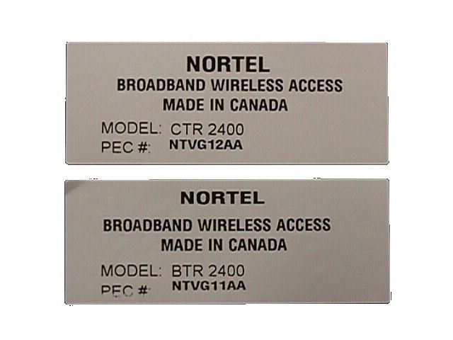
Nortel BWA Type Acceptance Radio Transceiver Test Report Product Description:24 GHz Base Station (BTR) and Customer Premise (CTR) Radio Transceivers Model:BTR2400 and CTR 2400 Nortel BWA File #00001-R01 CHARLIE BISHOP PI ENGINEERDATE ROMAN WROCZYNSKI PI MANAGERDATE WINNIPEG, Type Acceptance Test Report 00001-R01 ii DECLARATION BY Nortel Networks BWA The tests were performed from Oct 2 through Oct 21 at the Nortel Networks BWA’s EMC Laboratory in Winnipeg. The following personnel collaborated to this project: Mitch Hebert, Tech. Charlie Bishop, PI Engineer Testing was performed and supervised by the undersigned. The test supervisor attests to the accuracy of the test data recorded in this report. Performed by:Date Supervised by:Date © This document shall not be reproduced without the written approval of Nortel BWA Total number of pages: xx including x pages in appendices. The results presented in this report refer only to the product(s) described in section 1. All equipment and instrumentation used during this test have been verified and/or calibrated. All calibration certificates are traceable to the National Research Council of Canada (CNRC) and/or to the American National Institute of Standards and Technology (NIST) standards and can be provided on request. Nortel BWA is registered ISO 9001:1998, certificate no. xxx-xxxx-xx. Type Acceptance Test Report 00001-R01 iii TABLE OF CONTENTS Page 1. INTRODUCTION 5 OBJECT5 EQUIPMENT UNDER TEST DESCRIPTION5 APPLICATION AND EXCEPTIONS5 GENERAL5 DEVIATIONS5 RESULTS6 TEST FACILITIES DESCRIPTION6 TEST EQUIPMENT6 2. CONDUCTED EMISSIONS 7 TEST CONDITIONS7 MINIMUM SPECIFICATIONS7 TEST RESULTS7 MEASUREMENT DATA7 TEST METHOD8 TEST SYSTEM TEST CONFIGURATION8 3. RADIATED EMISSIONS 9 TEST CONDITIONS9 SPECIFICATIONS9 TEST RESULTS9 MEASUREMENT DATA9 TEST METHOD9 TEST SYSTEM CONFIGURATION10 4. TEMPERATURE STABILITY TESTS 11 TEST CONDITIONS11 SPECIFICATIONS11 TEST RESULTS11 MEASUREMENT DATA11 TEST METHOD11 TEST SYSTEM CONFIGURATION12 5. ADJACENT CHANNEL INTERFERENCE ERROR! BOOKMARK NOT DEFINED. Type Acceptance Test Report 00001-R01 iv TEST CONDITIONSERROR! BOOKMARK NOT DEFINED. SPECIFICATIONSERROR! BOOKMARK NOT DEFINED. TEST RESULTSERROR! BOOKMARK NOT DEFINED. MEASUREMENT DATAERROR! BOOKMARK NOT DEFINED. TEST METHODERROR! BOOKMARK NOT DEFINED. TEST SYSTEM CONFIGURATIONERROR! BOOKMARK NOT DEFINED. COMPUTER SETUP AND INSTRUMENTATION IN THE PI LABORATORY14 CONNECTION TO THE EUT USING THE WAVE-GUIDE CONNECTION14 PRODUCTION BTR 2400, 4 CARRIER QAM 64 MODULATED - IN-BAND CARRIERS15 PRODUCTION BTR 2400, 4 CARRIER QAM 64 MODULATED. – 30MHZ TO EDGE OF CARRIERS16 PRODUCTION BTR 2400, 4 CARRIER QAM 64 MODULATED. – EDGE OF CARRIERS TO 40GHZ17 PRODUCTION BTR 2400, 4 CARRIER QAM 64 MODULATED. – 40 TO 60GHZ18 PRODUCTION BTR 2400, 4 CARRIER QAM 64 MODULATED. – 60 TO 90GHZ19 PRODUCTION BTR 2400, 4 CARRIER QAM 64 MODULATED. – 90 TO 110GHZ20 CTR CONNECTED IN THE LABORATORY FOR CONDUCTED MEASUREMENTS22 CTR WITH THE CASE REMOVED22 PRODUCTION CTR 2400, CARRIERS23 PRODUCTION CTR 2400, 2 CARRIER QAM 64 MODULATED. – 30MHZ TO EDGE OF CARRIERS24 PRODUCTION CTR 2400, 2 CARRIER QAM 64 MODULATED. – EDGE OF CARRIERS TO 40GHZ25 PRODUCTION CTR 2400, 2 CARRIER QAM 64 MODULATED. – 40-60GHZ26 PRODUCTION CTR 2400, 2 CARRIER QAM 64 MODULATED. –60-90GHZ27 PRODUCTION CTR 2400, 2 CARRIER QAM 64 MODULATED. –90-110GHZ28 PRODUCTION BTR 2400, 4 CARRIER QAM 64 MODULATED. – 30MHZ TO 1GHZ31 PRODUCTION BTR 2400, 4 CARRIER QAM 64 MODULATED. – 1 TO 18 GHZ32 PRODUCTION BTR 2400, 4 CARRIER QAM 64 MODULATED. – 18GHZ TO EDGE OF CARRIERS33 PRODUCTION BTR 2400, 4 CARRIER QAM 64 MODULATED. – EDGE OF CARRIERS TO 40GHZ34 PRODUCTION BTR 2400, 4 CARRIER QAM 64 MODULATED. – 60-90GHZ35 PRODUCTION BTR 2400, 4 CARRIER QAM 64 MODULATED. - 90-110GHZ36 TEST SETUPERROR! BOOKMARK NOT DEFINED. TEST PLOT39 TEST RESULTS40 APPENDIX A:Conducted Emissions Measurement Results APPENDIX B:Radiated Emissions Measurement Results APPENDIX C:Temperature Stability Measurements Results. APPENDIX D:Adjacent Channel Interface Measurement Results Type Acceptance Test Report 00001-R01 5 1.INTRODUCTION Object The test results presented in this report will show conformity to the emissions profile indicated in Nortel Networks request for Waiver for point to multi-point radios operating in the 24 GHz DEMS band. The waiver has been appended to this test report. Equipment Under Test Description The Nortel Networks BWA 24 GHz radio product is of wide band design. The power amplifiers and the LNA are designed to provide gain over the entire 24.25 to 25.25 GHz band. The BTR and CTR are of a single conversion design. A single DRO serve both the transmit and receive path. The BTR and CTR provide a maximum power output of 1 and 0.5 watt respectively for a single unmodulated tone. Thus the power limitation requirement of FCC part 101 section 101.113 is satisfied. Photographs of the EUT are included in the appendix E of this report. The following table identifies the EUT: Model #DescriptionManufacturerPart # BTR2400Base TransceiverNortel BWANTVG11AA 03 CTR2400Customer TransceiverNortel BWAP0883603 Application and Exceptions General Tests were performed on a production sample(s) of the BTR and CTR, according to standards and directives indicated on the table in paragraph 1.1. All measurements were performed in accordance to the measurement procedures outlined in these standards or detailed in this report. Deviations The following deviations from, additions to, or exclusions from the test specifications have been made: None Type Acceptance Test Report 00001-R01 6 Results The following table summarizes the EUT test results of the testing described in this report: StandardTest DescriptionPara. No.Results FCC part 2, section 2.997; FCC part 101 section 101.111 (a) (4) Conducted Emissions2Non compliant to part 101 FCC part 2, Section 2.997, FCC part 101 section 101.111 (a) (4) Radiated Emissions3Non compliant to part 101 FCC part 2, Section 2.995 (a) (1), (b) and FCC p…
Text truncated - open the document above for the full version.
Nortel BWA Type Acceptance Radio Transceiver Test Report Product Description:24 GHz Base Station (BTR) and Customer Premise (CTR) Radio Transceivers Model:BTR2400 and CTR 2400 Nortel BWA File #00001-R01 CHARLIE BISHOP PI ENGINEERDATE ROMAN WROCZYNSKI PI MANAGERDATE WINNIPEG, Type Acceptance Test Report 00001-R01 ii DECLARATION BY Nortel Networks BWA The tests were performed from Oct 2 through Oct 21 at the Nortel Networks BWA’s EMC Laboratory in Winnipeg. The following personnel collaborated to this project: Mitch Hebert, Tech. Charlie Bishop, PI Engineer Testing was performed and supervised by the undersigned. The test supervisor attests to the accuracy of the test data recorded in this report. Performed by:Date Supervised by:Date © This document shall not be reproduced without the written approval of Nortel BWA Total number of pages: xx including x pages in appendices. The results presented in this report refer only to the product(s) described in section 1. All equipment and instrumentation used during this test have been verified and/or calibrated. All calibration certificates are traceable to the National Research Council of Canada (CNRC) and/or to the American National Institute of Standards and Technology (NIST) standards and can be provided on request. Nortel BWA is registered ISO 9001:1998, certificate no. xxx-xxxx-xx. Type Acceptance Test Report 00001-R01 iii TABLE OF CONTENTS Page 1. INTRODUCTION 5 OBJECT5 EQUIPMENT UNDER TEST DESCRIPTION5 APPLICATION AND EXCEPTIONS5 GENERAL5 DEVIATIONS5 RESULTS6 TEST FACILITIES DESCRIPTION6 TEST EQUIPMENT6 2. CONDUCTED EMISSIONS 7 TEST CONDITIONS7 MINIMUM SPECIFICATIONS7 TEST RESULTS7 MEASUREMENT DATA7 TEST METHOD8 TEST SYSTEM TEST CONFIGURATION8 3. RADIATED EMISSIONS 9 TEST CONDITIONS9 SPECIFICATIONS9 TEST RESULTS9 MEASUREMENT DATA9 TEST METHOD9 TEST SYSTEM CONFIGURATION10 4. TEMPERATURE STABILITY TESTS 11 TEST CONDITIONS11 SPECIFICATIONS11 TEST RESULTS11 MEASUREMENT DATA11 TEST METHOD11 TEST SYSTEM CONFIGURATION12 5. ADJACENT CHANNEL INTERFERENCE ERROR! BOOKMARK NOT DEFINED. Type Acceptance Test Report 00001-R01 iv TEST CONDITIONSERROR! BOOKMARK NOT DEFINED. SPECIFICATIONSERROR! BOOKMARK NOT DEFINED. TEST RESULTSERROR! BOOKMARK NOT DEFINED. MEASUREMENT DATAERROR! BOOKMARK NOT DEFINED. TEST METHODERROR! BOOKMARK NOT DEFINED. TEST SYSTEM CONFIGURATIONERROR! BOOKMARK NOT DEFINED. COMPUTER SETUP AND INSTRUMENTATION IN THE PI LABORATORY14 CONNECTION TO THE EUT USING THE WAVE-GUIDE CONNECTION14 PRODUCTION BTR 2400, 4 CARRIER QAM 64 MODULATED - IN-BAND CARRIERS15 PRODUCTION BTR 2400, 4 CARRIER QAM 64 MODULATED. – 30MHZ TO EDGE OF CARRIERS16 PRODUCTION BTR 2400, 4 CARRIER QAM 64 MODULATED. – EDGE OF CARRIERS TO 40GHZ17 PRODUCTION BTR 2400, 4 CARRIER QAM 64 MODULATED. – 40 TO 60GHZ18 PRODUCTION BTR 2400, 4 CARRIER QAM 64 MODULATED. – 60 TO 90GHZ19 PRODUCTION BTR 2400, 4 CARRIER QAM 64 MODULATED. – 90 TO 110GHZ20 CTR CONNECTED IN THE LABORATORY FOR CONDUCTED MEASUREMENTS22 CTR WITH THE CASE REMOVED22 PRODUCTION CTR 2400, CARRIERS23 PRODUCTION CTR 2400, 2 CARRIER QAM 64 MODULATED. – 30MHZ TO EDGE OF CARRIERS24 PRODUCTION CTR 2400, 2 CARRIER QAM 64 MODULATED. – EDGE OF CARRIERS TO 40GHZ25 PRODUCTION CTR 2400, 2 CARRIER QAM 64 MODULATED. – 40-60GHZ26 PRODUCTION CTR 2400, 2 CARRIER QAM 64 MODULATED. –60-90GHZ27 PRODUCTION CTR 2400, 2 CARRIER QAM 64 MODULATED. –90-110GHZ28 PRODUCTION BTR 2400, 4 CARRIER QAM 64 MODULATED. – 30MHZ TO 1GHZ31 PRODUCTION BTR 2400, 4 CARRIER QAM 64 MODULATED. – 1 TO 18 GHZ32 PRODUCTION BTR 2400, 4 CARRIER QAM 64 MODULATED. – 18GHZ TO EDGE OF CARRIERS33 PRODUCTION BTR 2400, 4 CARRIER QAM 64 MODULATED. – EDGE OF CARRIERS TO 40GHZ34 PRODUCTION BTR 2400, 4 CARRIER QAM 64 MODULATED. – 60-90GHZ35 PRODUCTION BTR 2400, 4 CARRIER QAM 64 MODULATED. - 90-110GHZ36 TEST SETUPERROR! BOOKMARK NOT DEFINED. TEST PLOT39 TEST RESULTS40 APPENDIX A:Conducted Emissions Measurement Results APPENDIX B:Radiated Emissions Measurement Results APPENDIX C:Temperature Stability Measurements Results. APPENDIX D:Adjacent Channel Interface Measurement Results Type Acceptance Test Report 00001-R01 5 1.INTRODUCTION Object This test report presents emissions profile of Nortel Networks BWA radios that are to operate in the 24 GHz DEMS band for the Type Acceptance of Nortel Networks BWA radios. Nortel Networks BWA radios cannot comply to the specifications referenced in the results section below, as our radios have been designed to provide mulit-carrier point-to-multipoint communication services. The present rules for 24 GHz DEMS do not regulate the emissions characteristics of mulit-carrier, pt-to-mpt radios. Our present customer has a license/waiver to commercially deploy services within this band, therefore it is Nortel Networks BWA intention to have our radio be blanketed under our customers waiver until such a time that the FCC formally performs a rule making for the 24GHz DEMS band. Nortel Networks BWA has identified our customer in our cover letter that has been supplied for this type acceptance filing, and furnished copies of their of number license/waiver for various installations sites in the United States. Equipment Under Test Description The Nortel Networks BWA 24 GHz radio product is of wide band design. The power amplifiers and the LNA are designed to provide gain over the entire 24.25 to 25.25 GHz band. The BTR and CTR are of a single conversion design. A single DRO serve both the transmit and receive path. The BTR and CTR provide a maximum power output of 1 and 0.5 watt respectively for a single unmodulated tone. Thus the power limitation requirement of FCC part 101 section 101.113 is satisfied. Photographs of the EUT are included in the appendix E of this report. The following table identifies the EUT: Model #DescriptionManufacturerPart # BTR2400Base TransceiverNortel BWANTVG11AA 03 CTR2400Customer TransceiverNortel BWAP0883603 Application and Exceptions General Tests were performed on a production sample(s) of the BTR and CTR, according to standard…
Text truncated - open the document above for the full version.
| # | Rule Parts | Frequency Range | Power Output | Emission | Tolerance |
|---|---|---|---|---|---|
| 1 | 101 | 24.25 GHz - 25.25 GHz | 1 W | 40M0D7W | 0.0030000000 % |