Text extracted from the exhibit documents filed with the FCC. Open a document above to read the original.
/10 Hitachi Asahi Electronics Co., Ltd. User’s Manual for Bluetooth Profile Unit Model: HA-1217 [Rev. R9] Read this manual thoroughly and keep it • Be sure to read safety descriptions in the manual and understand them before using this product. • Keep the manual at hand for your quick reference. /10 Introduction Thank you for purchasing the Bluetooth Profile Unit (HA-1217). The unit enables wireless data communication using Bluetooth and has the following features: • Bluetooth Serial Port Profile (SPP) is built in. • Bluetooth Class 2 transmission output power is supported, enabling wireless communication in the distance range of 10m with clear view. • Unique command interface enables command control and data communication using a single serial port. • Bluetooth-standard function for encrypted communication is supported. • Bluetooth-standard low power state function (PARK mode) is supported. Notices ? No part of this manual may be reproduced without permission. ? Contents of this manual may be subject to change without prior notice. ? Applications described in this manual show typical ones for use with our products. This manual never guarantees implementation of industrial property right and other rights or grants license. And also, any problems, related to industrial property right and others, resulting from using the product, arise with a third party, please note that we take no responsibility for them. ? Please note that we take no responsibility for effect led by the operation result regardless of the preceding clause. ? The unit is available for use in limited areas. If you are thinking of using it overseas, contact us. ? If you build the unit into another device and then use it in Japan, it is recommended that words such as “Contains wireless equipment with certification No.01NYCE1008” be labeled on the relevant device. ? If you build the unit into another device and then use it in North America, be sure to label the words “Contains FCC ID: NAB-AE-HA-1217” on the relevant device. Trademark notice Bluetooth is a trademark for Bluetooth SIG. Inc., USA. All Rights Reserved, Copyright(C) 2002,2003 Hitachi Asahi Electronics, Co.,Ltd. /10 Important Warning: abnormal heat, smoke and unusual sound/smell If something abnormal occurs during use, stop use the unit, turn the power off and disconnect the power cable immediately. Failure to do so may result in electric shock or fire. Caution: Interference Installing the unit adjacent to other electronics equipment may have harmful effects on each other. If equipment including TV and radio are existed near the unit, noises may be produced. In such case, do as described below. • Separate the unit from equipment including TV and radio as far as possible. • Reorient these equipment antennas. Precautions for Handling ? If the unit is used with systems, which require a high level of reliability and safety in their functions and performance, such as operation equipment (e.g. aircraft, train, vehicle), disaster/crime-prevention equipment and safety devices produced by various manufactures, please take the whole safety design into consideration by implementing fail-safe design or redundant design in order to maintain the reliability and safety of the whole of these systems/equipment. ? The unit is not intended to use with equipment, which requires extremely high level of reliability and safety, such as aerospace equipment, mainline-communication equipment, nuclear energy control equipment or life- support medical equipment. Never use the unit with these equipment. ? The unit is a communication device using radio waves in conformance with Bluetooth specifications. When the unit is used in places where radio waves are apt to spread out (e.g. outdoors where no obstacles exist) or where radio waves are not be transmitted smoothly indoors separated by walls, the transmittable distance may be changed, depending on the wave conditions. Please note that even during normal communication they may be interrupted, depending on the wave conditions ? The unit uses radio waves. Thus, there is possibility of getting wiretapped by third parties. If you require the communication to be concealed, use concealment process such as encryption function of the unit. ? Please note that we take no responsibility for pure economic loss resulting from losing a chance of communication or others due to wrong operation, malfunction or external factors including power failure. ? Installing the unit near microwave, TV, radio or speaker may produce harmful effects of noises and others. ? We take no responsibility for damages resulting from cases such as where the unit is used by deviating from its use conditions or precautions described in this manual. Precautions for Mounting / Installation ? The wireless unit complies with Radio Law. Never disassemble or modify it. Precautions for Operation ? Be sure to use the unit with rated voltage, temperature and humidity. Failure to do so may causes malfunction of the unit, and also its performance will not be guaranteed. /10 Tested to Comply With FCC Standards, FOR HOME OR OFFICE USE Federal Communication Commission Interference Statement This equipment has been tested and found to comply with the limits for a Class B digital device, pursuant to Part 15 of the FCC Rules. These limits are designed to provide reasonable protection against harmful interference in a residential installation. This equipment generates, uses and can radiate radio frequency energy and, if not installed and used in accordance with the instructions, may cause harmful interference to radio communications. However, there is no guarantee that interference will not occur in a particular installation. If this equipment does cause harmful interference to radio or television reception, which can be determined by turning the equipment off and on, the user is encouraged to try to correct the interference by one of the following measures: - Reorient or relocate the receiving antenna…
Text truncated - open the document above for the full version.
Confidential_letter (2496x3483x2 tiff)
power_of_attorney (2496x3483x2 tiff)
[email protected] www.adt.com.tw ADVANCE DATA TECHNOLOGY CORPORATION FEDERAL COMMUNICATIONS COMMISSION DECLARATION OF CONFORMITY (DoC) FOR THE FOLLOWING EQUIPMENT: PRODUCT NAME: Bluetooth Profile Unit MODEL NO.: HA-1217 TRADE NAME: Hitachi Asahi Electronics Co., Ltd. IS HEREWITH CONFIRMED AND FOUND TO COMPLY WITH THE REQUIREMENTS OF CFR 47 PART 15 REGULATION. THE RESULTS OF ELECTROMAGNETIC EMISSION EVALUATION ARE SHOWN IN THE REPORT NO.: RF920220R01 THIS DEVICE COMPLIES WITH PART 15 OF THE FCC RULES. OPERATION IS SUBJECT TO THE FOLLOWING TWO CONDITIONS: (1) THIS DEVICE MAY NOT CAUSE HARMFUL INTERFERENCE AND, (2) THIS DEVICE MUST ACCEPT ANY INTERFERENCE RECEIVED, INCLUDING INTERFERENCE THAT MAY CAUSE UNDESIRED OPERATION. THE FOLLOWING LOCAL MANUFACTURER/IMPORTER IS RESPONSIBLE FOR THIS DECLARATION: ManufacturerUSA Local Representative Company name: Hitachi Asahi Electoronics Co.,Ltd. To Be Determined. Address: 1, Ikegami, Haruoka, Owariasahi, Aichi- ken, Japan Contact Person: Hiroyuki Suzuki Title: Engineer Te l / F a x : Tel:+81-561-53-6386 Fax: :+81-561-51-4986
American Telecommunications Certification Body Inc. 6731 Whittier Ave, McLean, VA 22101 March 13, 2003 RE: FCC ID: NAB-AE-HA-1217 Attention: Ellis Wu I have a few comments on this Application. 1. The manual and FCD ID label information and setup photos clearly identifies this as a modular device. Please provide the modular request letter. 2. Please note, the manual states that this device is not to be collocated with any other transmitter or antenna. However, the manual also clearly shows the device used in conjunction with a Cell phone. Since 20 cm is the typical distance where collocation issues are considered to begin, the use in the cell phone would potentially be collocation. This device EIRP is 7.6mW and as such cannot be used in a portable configuration with collocated antenna(s) without certification by the FCC. Please explain or resolve the conflicting collocation issues with this manual. 3. Please note that modules are OEM installed. The use with the cell phone as stated in the manual would appear to violate this intent. Please explain how this device would be OEM installed in this situation. 4. Please note that the manual states this device can be used in a point to point ‘connection pattern’. Please note that this device has in integral antenna and is not capable of point to point use. Please clarify what the manual means in section 2.4 pertaining to cell phone and point to point use. Dennis Ward mailto:[email protected] The items indicated above must be submitted before processing can continue on the above referenced application. Failure to provide the requested information may result in application termination. Correspondence should be considered part of the permanent submission and may be viewed from the Internet after a Grant of Equipment Authorization is issued. Please do not respond to this correspondence using the email reply button. In order for your response to be processed expeditiously, you must submit your documents through the AmericanTCB.com website. Also, please note that partial responses increase processing time and should not be submitted. Any questions about the content of this correspondence should be directed to the sender.
1 dward From: [email protected] Sent: Sunday, March 16, 2003 10:36 PM To: [email protected] Cc: Ellis - ADT; [email protected] Subject: 回信: NAB-AE-HA-1217_ATCB000292 3-13-03 -AE-HA-1217_ATCB Dennis, 1) As I discussed with Bill that PCMCIA card can be taken as "end product", not "module". The device in this project has its own housing, it is the same with PCMCIA card except the interface which is defined by Hitach themselves. So, I think this card can also be taken as "end product", not "module". And also, "Stand-alone" test configuration can be always taken as the "wrose case". I don't think such configuration is only for "module approval". 2) No, this device will not be used in conjunction with a cell phone. In section 2.4, the product in this application is denoted as "BPU", not " BlueTooth Mobile Adapter". "BlueTooth Mobile Adapter" is the other device which is designed for Cell phone. Please be informed, the interface of BPU is NOT world wide defined. It will not be available on the external housing of the cell phone. 3) see answer above. 4) "Point to Point" connection is not what you think for outdoor used communication. "Point to Point" here means that the Master can only communicate with one Slave at one time. It is not designed to communicate with many slaves at one time. I hope I have answer your question. Thank you. Best Regards, Dr. Alan Lane Tel: +886 3 3270910 Fax: +886 3 3270892 "dward" <[email protected] 收件人: "Ellis - ADT" <[email protected]> m> 副本抄送: "Alan Lane" <[email protected]> 主旨: NAB-AE-HA-1217_ATCB000292 2003/03/14 03:14 AM 請回信 給 dward 2 Hi Ellis Comments attached. Thanks Dennis (See attached file: 3-13-03 NAB-AE-HA-1217_ATCB Comments.pdf)
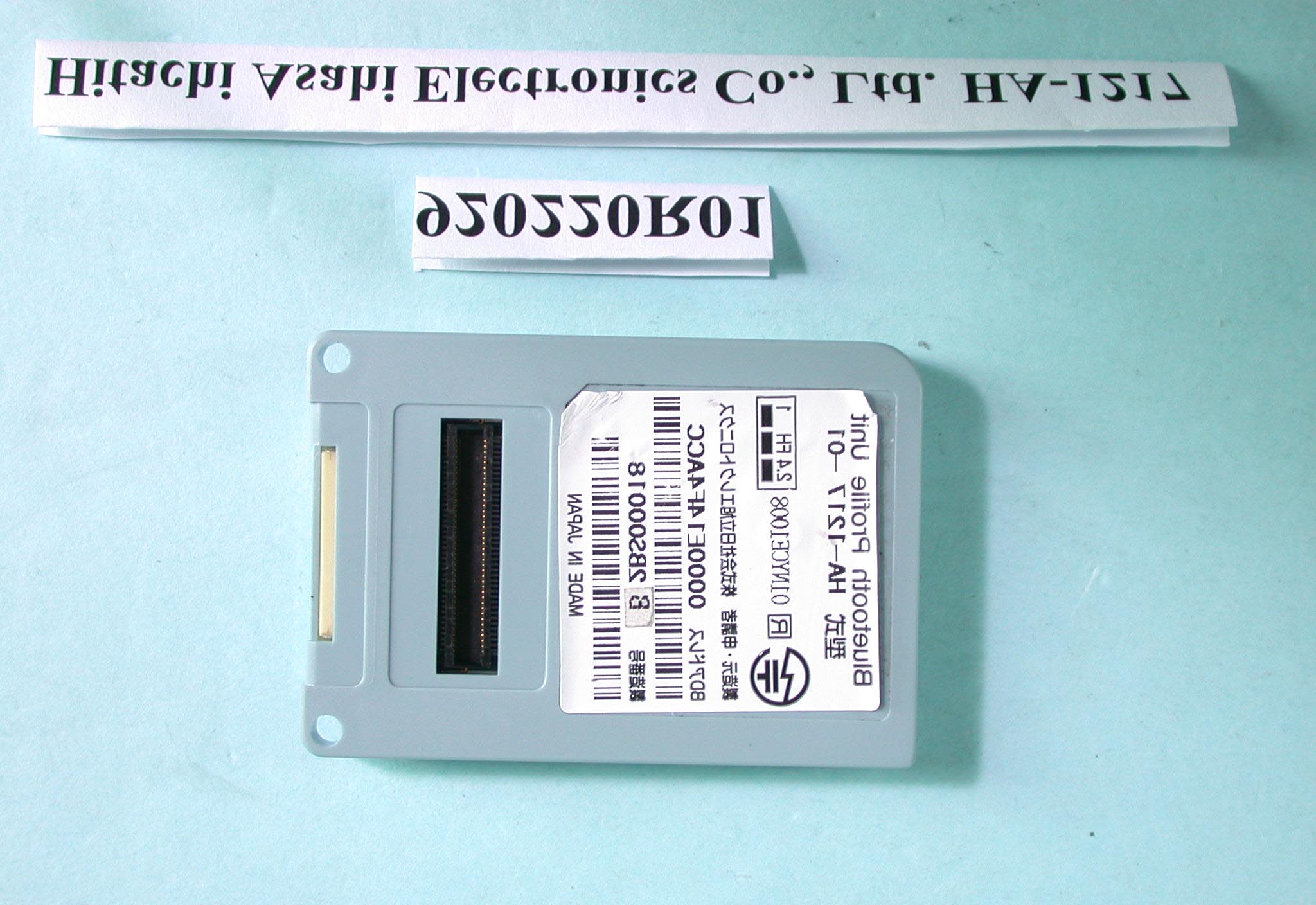
Page 1 ANNEX PHOTOGRAPHS OF EUT Page 2
Label (39.5) (9.8) (57)
Page 3 Page 4
FCC ID: NAB-AE-HA-1217 ADT No.920220R01 Operational Description This device is a Frequency Hopping device with 79 hopping frequencies. The antenna type is SMD antenna and there is no antenna connector used. The other instruction, please have a look at the users manual.
FCC ID: NAB-AE-HA-1217 Report No.: 920220R01 RF EXPOSURE TEST REPORT REPORT NO.: RF920220R01 MODEL NO.: HA-1217 ACCORDING: FCC Guidelines for Human Exposure IEEE C95.1 APPLICANT:Hitachi Asahi Electronics Co., Ltd. ADDRESS:1, Ikegami, Haruoka-cho, Owariasahi-shi, Aichi-ken, Japan ISSUED BY:Advance Data Technology Corporation LAB LOCATION:47 14th Lin, Chiapau Tsun, Linko, Taipei, Taiwan, R.O.C. 0528 ILAC MRA Lab Code: 200102-0 FCC ID: NAB-AE-HA-1217 Report No.: 920220R01 RF Exposure Measurement 1. Introduction 2.4 GHz frequency band is regarded specially as a dangerous band for its heating harmfulness to the human body. That’s why microwave oven is operating in this frequency band. The manufacturer whose product is working in this frequency band is obligatory to prove the harmfulness of his product. In this document, we try to prove the safety of radiation harmfulness to the human body for our product. The limit for Maximum Permissible Exposure (MPE) specified in FCC 1.1310 is followed. The Gain of the antenna used in this product is measured in a Fully Anechoic Chamber (FAC), and the maximum total power input to the antenna is measured. Through the Friis transmission formula and the maximum gain of the antenna, we can calculate the distance, away from the product, where the limit of MPE is reached. 2. RF Exposure Limit According to FCC 1.1310: The criteria listed in the following table shall be used to evaluate the environmental impact of human exposure to radio-frequency (RF) radiation as specified in 1.1307(b). FCC ID: NAB-AE-HA-1217 Report No.: 920220R01 LIMITS FOR MAXIMUM PERMISSIBLE EXPOSURE (MPE) Frequency Range (MHz) Electric Field Strength (V/m) Magnetic Field Strength (A/m) Power Density (mW/cm 2 ) Average Time (minutes) (A)Limits For Occupational / Control Exposures 30-30061.40.1631.06 300-1500......F/3006 1500-100,000......56 (B)Limits For General Population / Uncontrolled Exposure 30-30027.50.0730.230 300-1500......F/150030 1500-100,000......1.030 F = Frequency in MHz 3. Friis Formula Friis transmission formula : Pd = (Pout*G) / (4*pi*r 2 ) where Pd = power density in mW/cm 2 Pout = output power to antenna in mW G = gain of antenna in linear scale Pi = 3.1416 R = distance between observation point and center of the radiator in cm Pd is the limit of MPE, 1 mW/cm 2 . If we know the maximum Gain of the antenna and the total power input to the antenna, through the calculation, we will know the distance r where the MPE limit is reached. Ref. : David K. Cheng, Field and Wave Electromagnetics, Second Edition, Page 640, Eq. (11-133). 4. EUT Operating condition The software provided by Manufacturer enabled the EUT to transmit and receive data at lowest, middle and highest channel individually. FCC ID: NAB-AE-HA-1217 Report No.: 920220R01 5. Test Results 5.1 Antenna Gain The maximum Gain measured in Fully Anechoic Chamber is 3dBi or 2.0 (numeric). 5.2 Output Power Into Antenna & RF Exposure Distance : CHANNEL CHANNEL FREQUENCY (MHz) OUTPUT POWER TO ANTENNA (mW) MINIMUM ALLOWABLE DISTANCE ( r ) FROM SKIN (Centi-Meter) 024023.830.35 3924413.830.35 7824802.820.30 The minimum allowable distance is very close to the enclosure of the antenna. So, the user has no need to worry about the harmfulness of radiation.
FCC ID: NAB-AE-HA-1217 Report No.: RF920220R01 1 Issued: Mar. 3, 2003 FCC TEST REPORT REPORT NO.: RF920220R01 MODEL NO.: HA-1217 RECEIVED: Feb. 20, 2003 TESTED: Feb. 24 ~ 25, 2003 APPLICANT:Hitachi Asahi Electronics Co., Ltd. ADDRESS:1, Ikegami, Haruoka-cho, Owariasahi-shi, Aichi-ken, Japan ISSUED BY:Advance Data Technology Corporation LAB LOCATION:47 14th Lin, Chiapau Tsun, Linko, Taipei, Taiwan, R.O.C. This test report consists of 60 pages in total. It may be duplicated completely for legal use with the approval of the applicant. It should not be reproduced except in full, without the written approval of our laboratory. The client should not use it to claim product endorsement by CNLA, NVLAP or any government agencies. The test results in the report only apply to the tested sample. 0528 ILAC MRA Lab Code: 200102-0 FCC ID: NAB-AE-HA-1217 Report No.: RF920220R01 2 Issued: Mar. 3, 2003 TABLE OF CONTENTS 1CERTIFICATION.........................................................................................................4 2SUMMARY OF TEST RESULTS ................................................................................5 3GENERAL INFORMATION .........................................................................................6 3.1GENERAL DESCRIPTION OF EUT ...........................................................................6 3.2DESCRIPTION OF TEST MODES .............................................................................7 3.3GENERAL DESCRIPTION OF APPLIED STANDARDS .............................................7 3.4DESCRIPTION OF SUPPORT UNITS........................................................................7 4TEST PROCEDURES AND RESULTS .......................................................................8 4.1CONDUCTED EMISSION MEASUREMENT ..............................................................8 4.1.1 LIMITS OF CONDUCTED EMISSION MEASUREMENT ............................................8 4.1.2 TEST INSTRUMENTS................................................................................................8 4.1.3 TEST PROCEDURES ................................................................................................9 4.1.4 DEVIATION FROM TEST STANDARD .......................................................................9 4.1.5 TEST SETUP ...........................................................................................................10 4.1.6 EUT OPERATING CONDITIONS..............................................................................10 4.1.7 TEST RESULTS ....................................................................................................... 11 4.2NUMBER OF HOPPING FREQUENCY USED .........................................................17 4.2.1 LIMIT OF HOPPING FREQUENCY USED ...............................................................17 4.2.2 TEST INSTRUMENTS..............................................................................................17 4.2.3 TEST PROCEDURES ..............................................................................................18 4.2.4 DEVIATION FROM TEST STANDARD .....................................................................18 4.2.5 TEST SETUP ...........................................................................................................18 4.2.6 TEST RESULTS .......................................................................................................18 4.3DWELL TIME ON EACH CHANNEL.........................................................................21 4.3.1 LIMIT OF DWELL TIME USED .................................................................................21 4.3.2 TEST INSTRUMENTS..............................................................................................21 4.3.3 TEST PROCEDURES ..............................................................................................22 4.3.4 DEVIATION FROM TEST STANDARD .....................................................................22 4.3.5 TEST SETUP ...........................................................................................................22 4.3.6 TEST RESULTS .......................................................................................................23 4.4CHANNEL BANDWIDTH ..........................................................................................27 4.4.1 LIMITS OF CHANNEL BANDWIDTH........................................................................27 4.4.2 TEST INSTRUMENTS..............................................................................................27 4.4.3 TEST PROCEDURE.................................................................................................28 4.4.4 DEVIATION FROM TEST STANDARD .....................................................................28 4.4.5 TEST SETUP ...........................................................................................................28 4.4.6 EUT OPERATING CONDITION ................................................................................28 4.4.7 TEST RESULTS .......................................................................................................29 4.5HOPPING CHANNEL SEPARATION ........................................................................33 FCC ID: NAB-AE-HA-1217 Report No.: RF920220R01 3 Issued: Mar. 3, 2003 4.5.1 LIMIT OF HOPPING CHANNEL SEPARATION ........................................................33 4.5.2 TEST INSTRUMENTS..............................................................................................33 4.5.3 TEST PROCEDURES ..............................................................................................34 4.5.4 DEVIATION FROM TEST STANDARD .....................................................................34 4.5.5 TEST SETUP ...........................................................................................................34 4.5.6 TEST RESULTS ..............…
Text truncated - open the document above for the full version.
FCC ID: NAB-AE-HA-1217 Report No.: RF920220R01 39 Issued: Mar. 3, 2003 4.6 MAXIMUM PEAK OUTPUT POWER 4.6.1 LIMITS OF MAXIMUM PEAK OUTPUT POWER MEASUREMENT The Limit of Maximum Peak Output Power Measurement is 30dBm. 4.6.2 INSTRUMENTS Description & ManufacturerModel No.Serial No.Calibrated Until SPECTRUM ANALYZER8564EC4208A00660Nov. 20, 2003 NOTE: The calibration interval of the above test instruments is 12 months. And the calibrations are traceable to NML/ROC and NIST/USA. 4.6.3 TEST PROCEDURES 1. Check the calibration of the measuring instrument using either an internal calibrator or a known signal from an external generator. 2. Turn on the EUT and connect it to measurement instrument. Then set it to any one convenient frequency within its operating range. Set a reference level on the measuring instrument equal to the highest peak value. 3. The center frequency of the spectrum analyzer is set to the fundamental frequency and using 2 MHz RBW and 3 MHz VBW. 4. Measure the frequency difference of two frequencies that were attenuated 20dB from the reference level. Record the frequency difference as the emission bandwidth. 5. Repeat above procedures until all frequencies measured were complete. FCC ID: NAB-AE-HA-1217 Report No.: RF920220R01 40 Issued: Mar. 3, 2003 4.6.4 DEVIATION FROM TEST STANDARD No deviation 4.6.5 TEST SETUP For the actual test configuration, please refer to the related Item – Photographs of the Test Configuration. 4.6.6 EUT OPERATING CONDITION The software provided by client enabled the EUT to transmit and receive data at lowest, middle and highest channel frequencies individually. EUT SPECTRUM ANALYZER FCC ID: NAB-AE-HA-1217 Report No.: RF920220R01 41 Issued: Mar. 3, 2003 4.6.7 TEST RESULTS Output Power to Antenna: EUT Bluetooth Profile Unit MODEL HA-1217 INPUT POWER (SYSTEM) 120Vac, 60Hz ENVIRONMENTAL CONDITIONS 23deg.C, 64%RH, 1005hPa TESTED BY: Steven Lu CHANNEL CHANNEL FREQUENCY (MHz) PEAK POWER OUTPUT (dBm) PEAK POWER LIMIT (dBm) PASS/FAIL 024025.8330PASS 3924415.8330PASS 7824804.5030PASS FCC ID: NAB-AE-HA-1217 Report No.: RF920220R01 42 Issued: Mar. 3, 2003 Channel 0 FCC ID: NAB-AE-HA-1217 Report No.: RF920220R01 43 Issued: Mar. 3, 2003 Channel 39 FCC ID: NAB-AE-HA-1217 Report No.: RF920220R01 44 Issued: Mar. 3, 2003 Channel 78 FCC ID: NAB-AE-HA-1217 Report No.: RF920220R01 45 Issued: Mar. 3, 2003 4.7 RADIATED EMISSION MEASUREMENT 4.7.1 LIMITS OF RADIATED EMISSION MEASUREMENT Emissions radiated outside of the specified bands, shall be according to the general radiated limits in 15.209 as following: Frequencies (MHz) Field strength (microvolts/meter) Measurement distance (meters) 0.009-0.4902400/F(kHz)300 0.490-1.70524000/F(kHz)30 1.705-30.03030 30-881003 88-2161503 216-9602003 Above 9605003 NOTE: 1. The lower limit shall apply at the transition frequencies. 2. Emission level (dBuV/m) = 20 log Emission level (uV/m). 3. As shown in 15.35(b), for frequencies above 1000MHz, the field strength limits are based on average detector, however, the peak field strength of any emission shall not exceed the maximum permitted average limits, specified above by more than 20dB under any condition of modulation. FCC ID: NAB-AE-HA-1217 Report No.: RF920220R01 46 Issued: Mar. 3, 2003 4.7.2 TEST INSTRUMENTS DESCRIPTION & MANUFACTURER MODEL NO.SERIAL NO. CALIBRATED UNTIL * HP Spectrum Analyzer8594E3911A07465JuIy. 08, 2003 * HP Preamplifier8447D2944A10386Aug. 15, 2003 * HP Preamplifier8449B3008A01201Dec. 01, 2003 * HP Preamplifier8449B3008A01292Aug. 07, 2003 SCHAFFNER Tunable Dipole Antenna SCHWARZBECK Tunable Dipole Antenna VHBA 9123 UHA 9105 459 977 Nov. 22, 2003 ROHDE & SCHWARZ TEST RECEIVER ESCS 30836858/008Dec.13, 2003 * SCHAFFNER BILOG AntennaCBL6111C2727July. 17, 2003 * SCHWARZBECK Horn Antenna BBHA9120-D1D130July. 03, 2003 * EMCO Horn Antenna31159312-4192April 9, 2003 * ADT. Turn TableTT1000201NA * ADT. TowerAT1000201NA * SoftwareADT_Radiated_V5.06NANA * ANRITSU RF SwitchesMP59B6100237246Oct. 30, 2003 * TIMES RF cableLMR-600CABLE-ST10-01Oct. 30, 2003 NOTE:1. The calibration interval of the above test instruments is 12 months. And the calibrations are traceable to NML/ROC and NIST/USA. 2. “*” = These equipment are used for the final measurement. 3. The horn antenna and HP preamplifier (model: 8449B) are used only for the measurement of emission frequency above 1GHz if tested. 4. The test was performed in ADT Open Site No. 10. 5. The VCCI Site Registration No. is R-1248. FCC ID: NAB-AE-HA-1217 Report No.: RF920220R01 47 Issued: Mar. 3, 2003 4.7.3 TEST PROCEDURES a. The EUT was placed on the top of a rotating table 0.8 meters above the ground at a 10 meter open area test site. The table was rotated 360 degrees to determine the position of the highest radiation. b. The EUT was set 3 meters away from the interference-receiving antenna, which was mounted on the top of a variable-height antenna tower. c. The antenna is a broadband antenna, and its height is varied from one meter to four meters above the ground to determine the maximum value of the field strength. Both horizontal and vertical polarizations of the antenna are set to make the measurement. d. For each suspected emission, the EUT was arranged to its worst case and then the antenna was tuned to heights from 1 meter to 4 meters and the rotatable table was turned from 0 degrees to 360 degrees to find the maximum reading. e. The test-receiver system was set to Peak Detect Function and Specified Bandwidth with Maximum Hold Mode. f. If the emission level of the EUT in peak mode was 10 dB lower than the limit specified, then testing could be stopped and the peak values of the EUT would be reported. Otherwise the emissions that did not have 10 dB margin would be re- tested one by one using peak, quasi-peak or average method as specified and then reported in a data sheet. NOTE: 1. The resolution bandwidth and video bandwidth of test receiver/spectrum analyzer is 120kHz for Peak detection (PK) and Quasi-peak detection (QP) at freque…
Text truncated - open the document above for the full version.
FCC ID: NAB-AE-HA-1217 Report No.: RF920220R01 58 Issued: Mar. 3, 2003 5 PHOTOGRAPHS OF THE TEST CONFIGURATION CONDUCTED EMISSION TEST FCC ID: NAB-AE-HA-1217 Report No.: RF920220R01 59 Issued: Mar. 3, 2003 RADIATED EMISSION TEST
13-1, Lane19, WenShan 3rd ., St., · Taoyuan · Taiwan
| # | Rule Parts | Frequency Range | Power Output |
|---|---|---|---|
| 1 | 15C | 2.40 GHz - 2.48 GHz | 3.80 mW |
JBP - Part 15 Class B Computing Device Peripheral
Equipment Class
JBP - Part 15 Class B Computing Device Peripheral