NALASPRONETWAVE AIRSURFER PRO WLAN PC CARD, MODEL 1100-600
Nortel Networks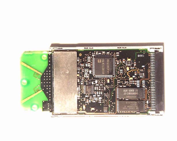
Click to zoom
Application Details
- Equipment Class
- DXX - Part 15 Low Power Communication Device Transmitter
- Date of Grant
- Aug 13, 1998
- Application Purpose
- Original Equipment
- Date of Application
- Jul 13, 1998
- Equipment Note
- NETWAVE AIRSURFER PRO WLAN PC CARD, MODEL 1100-600
- Frequency Range
- 2412.00000000 - 2462.00000000
- Company
- Nortel Networks
- Country
- Canada
Documents & Files
Document Text
Text extracted from the exhibit documents filed with the FCC. Open a document above to read the original.
Users Manual
AIRSURFER ® PRO WIRELESS LAN PC CARD IEEE 802.11 Standard Compliant USER’S GUIDE ® FCC NOTICE This equipment has been tested and found to comply with the limits for a Class B digital device, pursuant to Part 15 of the FCC Rules. These limits are designed to provide reasonable protection against harmful interference in a residential installation. This equipment generates, uses and can radiate radio frequency energy and, if not installed and used in accordance with the instructions, may cause harmful interference to radio communications. However, there is no guarantee that interference will not occur in a particular installation. If this equipment does cause harmful interference to radio or television reception, which can be determined by turning the equipment off and on, the user is encouraged to try to correct the interference by one or more of the following measures: • Reorient or relocate the receiving antenna. • Increase the separation between the equipment and receiver. • Connect the equipment into an outlet on a circuit different from that to which the receiver is connected. • Consult the dealer or an experienced radio/TV technician for help. Changes or modifications not expressly approved in writing by Netwave Technologies, Inc. may void the user’s authority to operate this equipment. This device complies with RSS-210 of Industry and Science Canada. Operation is subject to the following two conditions: (1) this device may not cause interference, and (2) this device must accept any interference, including interference that may cause undesired operation of the device. Netwave reserves the right to make improvements and/or changes in the products and programs described in this User’s Guide at any time without notice. The software described in this User’s Guide is furnished under a license and may be used or copied only in accordance with such license. ©1998 Netwave Technologies, Inc. All rights reserved. Neither this publication nor any part of this publication may be copied, photocopied, reproduced, translated or reduced to any electronic medium or machine readable form without the prior written permission of Netwave. Netwave ® and AirSurfer ® are a trademarks of Netwave Technologies, Inc. All other trademarks used in this publication are the property of their respective trademark holders. CONTENTS QUICK INSTALLATION GUIDE FOR WINDOWS 95 ................. 1 QUICK INSTALLATION GUIDE FOR WINDOWS NT ................. 3 INTRODUCTION................................................................ 5 Software .......................................................................... 6 Introduction to Netwave Networking ............................... 6 HARDWARE INSTALLATION............................................. 11 Unpacking and Inspection ............................................. 11 Package Contents ......................................................... 11 Additional Requirements ............................................... 12 Netwave AirSurfer PC Card Installation ........................ 12 Inserting the AirSurfer PC Card .................................... 12 Removing the AirSurfer PC Card .................................. 13 SYSTEM SETUP AND CONFIGURATION.............................. 15 Netwave AirSurfer Networks ......................................... 15 How to Modify the SSID ................................................ 16 Card and Socket Services ............................................. 18 NETWORK DRIVER INSTALLATION.................................... 19 Network Drivers ............................................................. 19 Installation for Microsoft Windows 95 ............................ 20 Installation for Microsoft Windows NT ........................... 22 NETWORK DRIVER REMOVAL.......................................... 25 NETWAVE AIRSURFER PRO UTILITIES............................... 31 Planning the Netwave Site ............................................ 32 DIAGNOSTICS AND TROUBLESHOOTING........................... 41 AirSurfer PC Card LED Indicators ................................. 41 Troubleshooting ............................................................ 41 APPENDIX A: Glossary of Netwave Terms.......................... 45 APPENDIX B: 24-Hour Global Suport Services..................... 53 APPENDIX C: Limited Warranty......................................... 55 APPENDIX D: Software License Agreement......................... 59 APPENDIX E: Specifications............................................. 61 1Netwave ® AirSurfer ® PRO PC Card User’s Guide QUICK INSTALLATION FOR WINDOWS 95 1.Boot your PC and wait until Windows 95 is up and running. NOTE If you have previously installed an AirSurfer ® or an AirSurfer Plus ® PC Card on your computer please follow the instructions in the Network Driver Removal section of this manual before proceeding with the installation. 2.Insert your AirSurfer Pro Wireless LAN PC Card into your PCMCIA Slot. 3.Windows 95 will automatically detect your card and display a “New Hardware Found” dialog box, identifying the “Netwave AirSurfer PRO Wireless LAN PC Card”. 4.Insert the AirSurfer Wireless LAN PC Card Windows 95/NT Installation disk into your 3_ floppy drive (A:). 5.Click “Next”. 6.Select the “Netwave AirSurfer Wireless LAN in 802.11 Mode Adapter” option. 7.If Windows 95 asks for the Windows 95 CD-ROM, enter the path to the Windows 95 setup files—either the drive letter of your CD- ROM drive or the directory of your Windows CAB files (these are often in C:\WINDOWS\OPTIONS\CABS). 8.If Windows 95 asks for the ASPNDIS3.SYS file, enter “A:”. 9.If you are running Novell’s IntraNetware Client 32, place the IntraNetware Installation CD in your CD-ROM drive when prompted. 10. Windows 95 will now ask you to restart. Select “No”. 11. Click the Start button, select Settings, Control Panel. 2Netwave ® AirSurfer ® PRO PC Card User’s Guide Quick Installation Guide for Windows 95 12. Double click the “Network” icon…
Text truncated - open the document above for the full version.
ID Label/Location Info
NALASPRO
Test Report
ENGINEERING TEST REPORT NETWAVE AIRSURFER PRO WLAN PC CARD Model No: 1100-6001 FCC ID: NALASPRO FCC PART 15, SUBPART C, PARA. 15.247 DIRECT SEQUENCE SPREAD SPECTRUM (DSSS) TRANSMITTERS OPERATING IN THE FREQUENCY BAND FROM 2412 - 2462 MHz UltraTech's FILE NO.: NTI-001FTX TESTED FOR: NETWAVE TECHNOLOGIES INC. 6663 Owens Drive Pleasanton, CA, USA 94588 TESTED BY: UltraTech Engineering Labs Inc. 4181 Sladeview Crescent, Unit 33 Mississauga, Ontario Canada L5L 5R2 PREPARED BY: Tri M. Luu, P.Eng. DATE: June 12, 1998 FCC PART 15, SUBPART C - DIRECT SEQUENCE SPREAD SPECTRUM TRANSMITTERS Page 2 NETWAVE AIRSURFER PRO WLAN PC CARD, Model 1100-6001FCC ID: NALASPRO UltraTech Engineering Labs Inc.UltraTech’s File #: NTI-001FTX 4181 Sladeview Cres., Unit 33, Mississauga, Ontario, Canada L5L 5R2Tel. #: 905-569-2550Fax. #: 905-569-2480 • Accredited by ITI (UK) Competent Body & NVLAP (USA) Accreditation Body • Recognized/Listed by FCC (USA), Industry Canada (Canada), Austel (Australia) • All test results contained in this engineering test report are traceable to National Institute of Standards and Technology (NIST) TABLE OF CONTENTS 1.EXHIBIT 1 - SUMMARY OF TEST RESULTS & GENERAL STATEMENT OF CERTIFICATION........3 2.EXHIBIT 2 - GENERAL INFORMATION.......................................................................................................5 2.1APPLICANT.....................................................................................................................................................5 2.2MANUFACTURER............................................................................................................................................5 2.3DESCRIPTION OF EQUIPMENT UNDER TEST.......................................................................................................5 2.4RELATED SUBMITTAL(S)/GRANT.....................................................................................................................6 2.5TEST METHODOLOGY.....................................................................................................................................6 2.6TEST FACILITY...............................................................................................................................................6 2.7UNITS OF MEASUREMENTS..............................................................................................................................6 3.EXHIBIT 3 - SYSTEM TEST CONFIGURATION..........................................................................................7 3.1TEST SYSTEM DETAILS...................................................................................................................................7 3.2 BLOCK DIAGRAMS RADIATED EMISSION MEASUREMENTS.................................................................................7 3.3PHOTOGRAPH FOR RF EMISSION MEASUREMENTS............................................................................................8 3.4JUSTIFICATION...............................................................................................................................................14 3.5EUT OPERATING CONDITION.........................................................................................................................14 3.6SPECIAL ACCESSORIES...................................................................................................................................14 3.7EQUIPMENT MODIFICATIONS..........................................................................................................................14 4.EXHIBIT 4 - TEST DATA................................................................................................................................15 4.16 DB BANDWIDTH @ FCC CFR 47, PARA 15.247(A)(2).................................................................................15 4.2MAXIMUM PEAK OUTPUT POWER @ FCC 15.247(B) AND RF EXPOSURE LIMIT FCC 1.1310............................19 4.3RF CONDUCTED EMISSIONS AT THE TRANSMITTER ANTENNA TERMINAL, FCC CFR 47, PARA. 15.247(C)........23 4.4TRANSMITTER RADIATED EMISSIONS @ 3 METERS, FCC CFR 47, PARA. 15.247(C), 15.209 & 15.205............37 4.5TRANSMITTED POWER DENSITY OF A DIRECT SEQUENCE SPREAD SPECTRUM SYSTEM, FCC CFR 47, PARA. 15.247(D).................................................................................................................................................................58 4.6PROCESSING GAIN OF A DIRECT SEQUENCE SPREAD SPECTRUM, FCC CFR 47, PARA. 15.247(E).....................62 4.7AC POWERLINE CONDUCTED EMISSIONS, FCC CFR 47, PARA. 15.107(A)......................................................78 5.EXHIBIT 5 - GENERAL TEST PROCEDURES.............................................................................................81 5.1AC POWERLINE CONDUCTED EMISSIONS MEASUREMENTS - GENERAL TEST METHOD......................................81 5.2ELECTRICAL FIELD RADIATED EMISSIONS MEASUREMENTS - GENERAL TEST METHOD.....................................83 6.EXHIBIT 6 - INFORMATION RELATED TO EQUIPMENT UNDER TESTS............................................86 6.1FCC ID LABELING AND SKETCH OF FCC LABEL LOCATION............................................................................86 6.2PHOTOGRAPHS OF EQUIPMENT UNDER TEST....................................................................................................86 6.3SYSTEM BLOCK DIAGRAM(S)..........................................................................................................................86 6.4SCHEMATIC DIAGRAMS AND PART LISTS.........................................................................................................86 6.5USER’S MANUAL WITH “FCC INFORMATION TO USER STATEMENTS”...............................................................86 FCC PART 15, SUBPART C - DIRECT SEQUENCE SPREAD SPECTRUM TRANSMITTERS Page 3 NETWAVE AIRSURFER PRO WLAN PC CARD, Model 1100-6001FCC ID: NALASPRO Ul…
Text truncated - open the document above for the full version.
Test Report
Page 1 of 24Report No.3014 51 Spectrum WayTel. (613) 820 2730 Nepean, Ontario K2R 1E6Fax (613) 820 4161 e-mail: [email protected] Since 1981 Research * Training * Consulting * Testing Solutions for the Wireless Future CERTIFICATION REPORT Subject:Specific Absorption Rate (SAR) Experimental Analysis Product:Netwave AirSurfer™ Pro Wireless LAN PCMCIA Card Client:Netwave Technologies Address:6663 Owens Drive Pleasanton, CA 94588 Project #NETB-AirSurferPro-3014 Prepared by:APREL Laboratories 51 Spectrum Nepean, Ontario K2R 1E6 Submitted By original signed byDate: 14 July, 1998 Dr. Paul G. Cardinal Director, Laboratories Approved By original signed and stamped by Date: 14 July, 1998 Dr. Jacek J. Wojcik, P.Eng. Page 2 of 24Report No.3014 51 Spectrum WayTel. (613) 820 2730 Nepean, Ontario K2R 1E6Fax (613) 820 4161 e-mail: [email protected] Since 1981 Research * Training * Consulting * Testing Solutions for the Wireless Future FCC ID:NALASPRO Applicant:Netwave Technologies Equipment:Wireless LAN PCMCIA Card Model:AirSurfer Pro Standard:FCC 96-326, Guidelines for Evaluating the Environmental Effects of Radio- Frequency Radiation ENGINEERING SUMMARY This report contains the results of the engineering evaluation performed on a Netwave Technologies AirSurfer Pro Wireless LAN PCMCIA Card. The measurements were carried out in accordance with FCC 96-326. The handset was evaluated at its nominal maximum power level of 22dBm (158mW). The AirSurfer Pro PCMCIA card was tested at high, middle and low frequencies, with the maximum SAR channel 7 (mid). Test data and graphs are presented in this report. Based on the test results, it is certified that the product meets the requirements as set forth in the above specification, for an uncontrolled RF exposure environment. Page 3 of 24Report No.3014 51 Spectrum WayTel. (613) 820 2730 Nepean, Ontario K2R 1E6Fax (613) 820 4161 e-mail: [email protected] Since 1981 Research * Training * Consulting * Testing Solutions for the Wireless Future TABLE OF CONTENTS 1.0INTRODUCTION 2.0APPLICABLE DOCUMENTS 3.0EQUIPMENT UNDER TEST 4.0TEST EQUIPMENT 5.0TEST METHODOLOGY 6.0TEST RESULTS 7.0 CONCLUSIONS APPENDICES A. Manufacturer’s Antenna Specifications B. Uncertainty Budget C. Tissue Properties D. Validation Scans Page 4 of 24Report No.3014 51 Spectrum WayTel. (613) 820 2730 Nepean, Ontario K2R 1E6Fax (613) 820 4161 e-mail: [email protected] Since 1981 Research * Training * Consulting * Testing Solutions for the Wireless Future 1.0INTRODUCTION Tests were conducted to determine the Specific Absorption Rate (SAR) of a sample of a Netwave Technologies AirSurfer Pro Wireless LAN PCMCIA Card. These tests were conducted at APREL Laboratories’ facility located at 51 Spectrum Way, Nepean, Ontario, Canada. The view of the SAR laboratory can be seen in Figure 1. This report describes the results obtained. 2.0APPLICABLE DOCUMENTS The following documents are applicable to the work performed: 1)FCC 96-326, Guidelines for Evaluating the Environmental Effects of Radio- Frequency Radiation 2)ANSI/IEEE C95.1-1992, IEEE Standard for Safety Levels with Respect to Human Exposure to Radio Frequency Electromagnetic Fields, 3 kHz to 300 GHz. 3) ANSI/IEEE C95.3-1992, IEEE Recommended Practice for the Measurement of Potentially Hazardous Electromagnetic Fields – RF and Microwave. 4) OET Bulletin 65 (Edition 97-01) Supplement C (Edition 97-01), “Evaluating Compliance with FCC Guidelines for Human Exposure to Radiofrequency Electromagnetic Fields”. 3.0EQUIPMENT UNDER TEST • Netwave Technologies AirSurfer Pro Wireless LAN PCMCIA Card, (sample 1). • Netwave Technologies AirSurfer Pro Wireless LAN PCMCIA Card, (sample 2). The transmit antenna is a monopole type with approximately –2dBi gain. The antenna specifications supplied by the manufacturer can be found in Appendix A. Sample 2’s antenna was disabled and an RF connector was connected to the antenna feedpoint in order to be able to monitor the battery condition before and after each SAR scan. Page 5 of 24Report No.3014 51 Spectrum WayTel. (613) 820 2730 Nepean, Ontario K2R 1E6Fax (613) 820 4161 e-mail: [email protected] Since 1981 Research * Training * Consulting * Testing Solutions for the Wireless Future 4.0TEST EQUIPMENT • Narda 8021B miniature E-field probe, S/N 04007, Asset # 301339. • CRS Robotics A255 articulated robot arm, S/N RA2750, Asset # 301355. • CRS Robotics C500 robotic system controller, S/N RC584, Asset # 201354. • Rohde & Schwarz NRVS, power meter, S/N 864268/017, Asset # 100851. • Rohde & Schwarz NRV-Z7, power sensor, S/N 862509/006, Asset # 100852. • APREL F-1, Flat Manikin, S/N 001. • Tissue Recipe and Calibration Requirements, APREL procedure SSI/DRB-TP-D01- 033. 5.0TEST METHODOLOGY 1) The test methodology utilized in the certification of the Wireless LAN PCMCIA Card complies with the requirements of FCC 96-326 and ANSI/IEEE C95.3-1992, (IEEE Recommended Practice for the Measurement of Potentially Hazardous Electromagnetic Fields – RF and Microwave). 2) The E-field is measured with a small isotropic probe (output voltage proportional to E 2 ). 3) The probe is moved precisely from one point to the next using the robot (1cm increments for wide area scanning and 0.5cm increments for the final measurements). 4) The probe travels in the homogeneous liquid simulating human tissue. Appendix C contains information about the recipe and properties of the simulated tissue. 5) The liquid is contained in a flat manikin simulating a human lap. 6) The PCMCIA card is inserted into a laptop computer and this is positioned in a normal usage position against the lap simulating flat manikin. 7) All tests were performed with the highest power available from the sample PCMCIA wireless LAN card, under transmit conditions. Page 6 of 24Report No.3014 51 Spectrum WayTel. (613) 820 2730 Nepean, Ontario K2R 1E6Fax (613) 820 4161 e-mail: [email protected] Since 1981 Research * Training * Consulting * Testing Solutions for the Wireless Future More detailed descriptions of the tes…
Text truncated - open the document above for the full version.
Contact Information
Applicant
Thomas Wong(Regulatory Prime, Wireless Division)
Technical Contact
Ultratech Engineering Labs Inc.Tri M Luu
[email protected]1-800-263-7670
4181 Sladeview Crescent, Unit 33 · Mississauga, Ontario · Canada
Non-Technical Contact
Ultratech Engineering Labs Inc.Tri M Luu
[email protected]1-800-263-7670
Test Firm
UltraTech Engineering Labs Inc.Tri Luu
Technical Specifications
| # | Rule Parts | Frequency Range | Power Output | Tolerance |
|---|---|---|---|---|
| 1 | 15C | 2.41 GHz - 2.46 GHz | - | % |