NBXEPX-105NPager
Diva Telecom Inc
Click to zoom
Application Details
- Equipment Class
- CXX - Communications Rcvr for use w/ licensed Tx and CBs
- Date of Grant
- May 19, 1999
- Application Purpose
- Original Equipment
- Date of Application
- Dec 09, 1998
- Equipment Note
- Pager
- Frequency Range
- 140.00000000 - 159.00000000
- Company
- Diva Telecom Inc
- Country
- United States
Documents & Files
Document Text
Text extracted from the exhibit documents filed with the FCC. Open a document above to read the original.
Users Manual
COMMUNICATION CERTIFICATION LABORATORYTEST REPORT: 73-6658 FCC ID: NBXEPX-105N Page 30 of 39 Exhibit 8 Exhibit 8: User’s Manual The user’s manual is enclosed below. The compliance statement for the EPX-105N is enclosed on page 26 of the manual. COMMUNICATION CERTIFICATION LABORATORYTEST REPORT: 73-6658 FCC ID: NBXEPX-105N Page 31 of 39 Exhibit 8 COMMUNICATION CERTIFICATION LABORATORYTEST REPORT: 73-6658 FCC ID: NBXEPX-105N Page 32 of 39 Exhibit 8 COMMUNICATION CERTIFICATION LABORATORYTEST REPORT: 73-6658 FCC ID: NBXEPX-105N Page 33 of 39 Exhibit 8
Block Diagram
COMMUNICATION CERTIFICATION LABORATORYTEST REPORT: 73-6658 FCC ID: NBXEPX-105N Page 5 of 39 Exhibit 4 Exhibit 4: Block Diagrams COMMUNICATION CERTIFICATION LABORATORYTEST REPORT: 73-6658 FCC ID: NBXEPX-105N Page 6 of 39 Exhibit 5 Exhibit 5: Schematic Diagrams
Cover Letter(s)
COMMUNICATION CERTIFICATION LABORATORYTEST REPORT: 73-6658 FCC ID: NBXEPX-105N Page 39 of 39 Exhibit 13 Exhibit 13: Cover Letters December 11, 1998 FEDERAL COMMUNICATIONS COMMISSION Equipment Authorization Division 7435 Oakland Mills Road Columbia, MD 21046 To Whom It May Concern: Enclosed is a FCC Part 15, Subpart B, Certification application for the Diva Telecom, Inc. Model EPX-105N, FCC ID: NBXEPX-105N Please let me know if I can be of further assistance. Sincerely yours, COMMUNICATION CERTIFICATION LABORATORY Joseph W. Jackson VP Marketing
External Photos
COMMUNICATION CERTIFICATION LABORATORYTEST REPORT: 73-6658 FCC ID: NBXEPX-105N Page 3 of 39 Exhibit 3 Exhibit 3: Photographs of Overall Appearance Front View of the EPX-105N COMMUNICATION CERTIFICATION LABORATORYTEST REPORT: 73-6658 FCC ID: NBXEPX-105N Page 4 of 39 Exhibit 3 Back View of the EPX-105N
ID Label/Location Info
COMMUNICATION CERTIFICATION LABORATORYTEST REPORT: 73-6658 FCC ID: NBXEPX-105N Page 1 of 39 Exhibit 1 Exhibit 1: FCC ID Label Equipment Identification Label In accordance with the requirements of Sections 15.19 (a), 2.925 and 2.926 of the FCC Rules, the following information will be permanently affixed to the Diva Telecom Inc. Model EPX-105N as shown in the photograph below. Due to the size of the equipment, the label contains only the FCC ID only, and the compliance statement is provided in the User’s manual. The compliance statement for the EPX-105N is enclosed on page 26 of the manual. Photograph of the back exterior view.
Internal Photos
COMMUNICATION CERTIFICATION LABORATORYTEST REPORT: 73-6658 FCC ID: NBXEPX-105N Page 34 of 39 Exhibit 9 Exhibit 9: Internal Photographs Component Side of the EPX-105N COMMUNICATION CERTIFICATION LABORATORYTEST REPORT: 73-6658 FCC ID: NBXEPX-105N Page 35 of 39 Exhibit 9 Alternate Component Side of the EPX-105N
Schematics
COMMUNICATION CERTIFICATION LABORATORYTEST REPORT: 73-6658 FCC ID: NBXEPX-105N Page 6 of 39 Exhibit 5 Exhibit 5: Schematic Diagrams
Test Report
COMMUNICATION CERTIFICATION LABORATORYTEST REPORT: 73-6658 FCC ID: NBXEPX-105N Page 7 of 39 Exhibit 6 Exhibit 6: Test Report TEST REPORT FROM: COMMUNICATION CERTIFICATION LABORATORY 1940 W. Alexander Street Salt Lake City, Utah 84119-2039 Type of Report: Certification TEST OF: EPX-105N FCC ID: NBXEPX-105N To FCC PART 15, Subpart B Test Report Serial No: 73-6658 Applicant: Diva Telecom Inc. 6 West 33 rd Street New York, NY 10001 Date of Test: November 3-4, 1998 Issue Date: December 7, 1998 COMMUNICATION CERTIFICATION LABORATORYTEST REPORT: 73-6658 FCC ID: NBXEPX-105N Page 8 of 39 Exhibit 6 CERTIFICATION OF ENGINEERING REPORT This report has been prepared by Communication Certification Laboratory to determine compliance of the device described below with the requirements of FCC Part 15, Subpart B. This report may be reproduced in full, partial reproduction may only be made with the written consent of the laboratory. The results in this report apply only to the sample tested. -Applicant:Diva Telecom Inc. -Manufacturer:Diva Telecom Inc. -Brand Name:Diva -Model Number:EPX-105N -FCC ID:NBXEPX-105N On this 13th day of November 1998, I, individually, and for Communication Certification Laboratory, certify that the statements made in this engineering report are true, complete, and correct to the best of my knowledge, and are made in good faith. Although NVLAP has recognized that the Communication Certification Laboratory EMC testing facilities are in good standing, NVLAP does not endorse the product described in this report. COMMUNICATION CERTIFICATION LABORATORY Checked by: Roger J. Midgley EMC Engineering Manager Tested by: Richard L. Winter EMC Technician COMMUNICATION CERTIFICATION LABORATORYTEST REPORT: 73-6658 FCC ID: NBXEPX-105N Page 9 of 39 Exhibit 6 SECTION 1.0 CLIENT INFORMATION 1.1 Client Information: Company Name: Diva Telecom Inc. 6 West 33 rd Street New York, NY 10001 Contact Name: Chris Kim Title:President Signature: COMMUNICATION CERTIFICATION LABORATORYTEST REPORT: 73-6658 FCC ID: NBXEPX-105N Page 10 of 39 Exhibit 6 SECTION 2.0 EQUIPMENT UNDER TEST (EUT) 2.1 Identification of EUT: Trade Name:Diva Model Name or Number:EPX-105N Serial Number:N/A Options Fitted:N/A Country of Manufacture:Korea 2.2 Description of EUT: The EPX-105N radio pager is a super-heterodyne receiver of alpha numeric display type. The EXP-105N utilizes POCSAG (CCIR CODE #1) code format operating at 512/1200/2400 BPS. The EXP-105N operates from 140 to 159 MHz. The EXP-105N receives it power from a 1.5 (AAA) Volt battery. 2.3 EUT and Support Equipment: Not Applicable. 2.4 Interface Ports on EUT: Not Applicable. 2.5 Modification Incorporated/Special Accessories on EUT: There were no modifications or special accessories required, to comply with the specification. COMMUNICATION CERTIFICATION LABORATORYTEST REPORT: 73-6658 FCC ID: NBXEPX-105N Page 11 of 39 Exhibit 6 SECTION 3.0 TEST SPECIFICATION, METHODS & PROCEDURES 3.1 Test Specification: Title:FCC PART 15, Subpart B (47 CFR 15). Limits, and methods of measurement of radio interference characteristics of radio frequency devices. Purpose of Test: The tests were performed to demonstrate Initial compliance. 3.2 Methods & Procedures: 3.2.1 15.107 Conducted Limits (a) Except for Class A digital devices, and for equipment that is designed to be connected to the public utility. AC power line, the radio frequency voltage that is conducted back onto the AC power line on any frequency or frequencies within the band 450 kHz to 30 MHz shall not exceed 250 microvolts. Compliance with the provision shall be based on the measurement of the radio frequency voltage between each power line and ground at the power terminals. (b) For a Class A digital device that is designed to be connected to the public utility (AC) power line. The radio frequency voltage that is conducted back onto the AC power line on any frequency or frequencies within the band 450 kHz to 30 MHz shall not exceed the limits in the following table. Compliance with this provision shall be based on the measurement of the radio frequency voltage between each power line and ground at the power terminals. The lower limit applies at the band edges. Frequency of emission (MHz) Conducted limit (microvolts) 0.45 - 1.7051000 1.705 - 30.03000 3.2.2 15.109 Radiated Limits (a) Except for Class A digital devices, the field strength of radiated emissions from unintentional radiators at a distance of 3 meters shall not exceed the following values: COMMUNICATION CERTIFICATION LABORATORYTEST REPORT: 73-6658 FCC ID: NBXEPX-105N Page 12 of 39 Exhibit 6 Frequency of emission (MHz) Field Strength (microvolts/meter) 30 - 88100 88 - 216150 216 - 960200 Above 960500 (b) The field strength of radiated emission from a Class A digital device, as determined at a distance of 10 meters, shall not exceed the following: Frequency of emission (MHz) Field Strength (microvolts/meter) 30 - 8890 88 - 216150 216 - 960210 Above 960300 (c) In the emission tables above, the tighter limit applies at the band edges. 15.33 and 15.35, which specify the frequency range over which radiated emissions are to be measured, and the detector functions and other measurement standards apply. 3.2.3 Test Procedure The line conducted and radiated emissions testing was performed according to the procedures in ANSI C63.4 (1992). Line conducted and radiated emissions testing was performed at CCL’s anechoic chamber located in Salt Lake City, Utah. This site has been fully described in a report submitted to the FCC, and was accepted in a letter dated March 6, 1996 (31040/SIT). CCL participates in the National Voluntary Laboratory Accreditation Program (NVLAP) and has been accepted under NVLAP Lab Code: 100272-0, which is effective until September 30,1999. For radiated emissions testing that is performed at distances closer than the specified distance, an inverse proportionality factor of 20 dB per decade is used to normalize the measured data for determining complianc…
Text truncated - open the document above for the full version.
Test Setup Photos
COMMUNICATION CERTIFICATION LABORATORYTEST REPORT: 73-6658 FCC ID: NBXEPX-105N Page 29 of 39 Exhibit 7 Exhibit 7: Test Set-Up Photographs Front view of worst case radiated emissions
Contact Information
Applicant
Chris Y Kim(President)
212 897-0000Fax: 212 897-1111
Technical Contact
Communication Certification LaboratoryRoger J Midgley
[email protected]801-972-6146
1940 W. Alexander St. · Salt Lake City, Utah · United States
Test Firm
Communication Certification Lab.Scott Earl
Technical Specifications
| # | Rule Parts | Frequency Range | Power Output |
|---|---|---|---|
| 1 | 15B | 140 MHz - 159 MHz | - |
Other Applications from Diva Telecom Inc
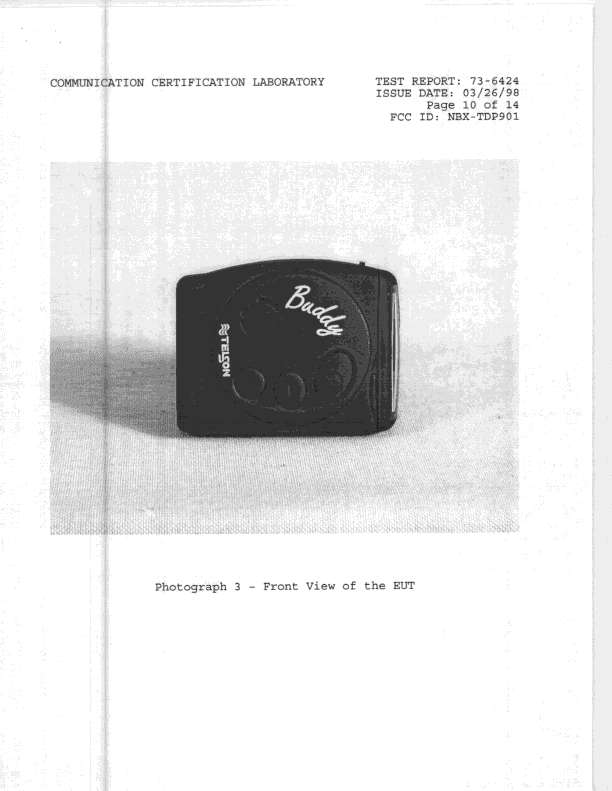
NBX-TDP901
May 31, 1998Pager
Equipment Class
CXX - Communications Rcvr for use w/ licensed Tx and CBsNBX-TDP9000
May 12, 1998CXX - Communications Rcvr for use w/ licensed Tx and CBs
Equipment Class
CXX - Communications Rcvr for use w/ licensed Tx and CBsNBX-TUP450W
May 12, 1998CXX - Communications Rcvr for use w/ licensed Tx and CBs
Equipment Class
CXX - Communications Rcvr for use w/ licensed Tx and CBsNBX-TUP900W
May 12, 1998CXX - Communications Rcvr for use w/ licensed Tx and CBs
Equipment Class
CXX - Communications Rcvr for use w/ licensed Tx and CBsNBX-TSP150W
Apr 21, 1998CXX - Communications Rcvr for use w/ licensed Tx and CBs
Equipment Class
CXX - Communications Rcvr for use w/ licensed Tx and CBs