NC82-963810 Channel Cordless Phone with Caller ID
CCT Tech Advanced Products Limited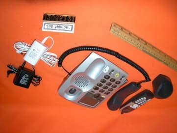
Click to zoom
Application Details
- Equipment Class
- ETS - Part 15 Cordless Telephone System
- Date of Grant
- Jul 09, 2002
- Application Purpose
- Original Equipment
- Date of Application
- Jul 09, 2002
- Equipment Note
- 10 Channel Cordless Phone with Caller ID
- Frequency Range
- 49.67000000 - 49.99000000
- Country
- Hong Kong
Documents & Files
Document Text
Text extracted from the exhibit documents filed with the FCC. Open a document above to read the original.
Block Diagram
6738BBOX1.SCH-1 - Fri Jun 14 16:27:01 2002 6738HBOX1.SCH-1 - Fri Jun 14 16:29:58 2002
External Photos
External photos FCC ID: NC82-9638 External photos FCC ID: NC82-9638
ID Label/Location Info
THIS THIS DEVICE DEVICE COMPLIES COMPLIES WITH WITH PART PART 15 15 OF OF THE THE FCC FCC RULES.RULES. OPERATION OPERATION IS IS SUBJECT SUBJECT TO TO THE THE FOLLOWING FOLLOWING TWO TWO CONDITIONS: CONDITIONS: (1) (1) THIS THIS DEVICE DEVICE MAY MAY NOT NOT CAUSE CAUSE HARMFULHARMFUL INTERFERENCE, AND (2) THIS DEVICE MUST ACCEPT ANYINTERFERENCE, AND (2) THIS DEVICE MUST ACCEPT ANY INTERFERENCE RECEIVED INCLUDING INTERFERENCE INTERFERENCE RECEIVED INCLUDING INTERFERENCE THAT THAT MAY MAY CAUSE CAUSE UNDESIRED UNDESIRED OPERATION.OPERATION. PRIVACY PRIVACY OF OF COMMUNICATIONS COMMUNICATIONS MAY MAY NOT NOT BE BE ENSUREDENSURED WHEN WHEN USING USING THIS THIS PHONE.PHONE. ATLINKS ATLINKS MODEL: EX29638XXX-A MODEL: EX29638XXX-A HACHAC CORD TELEPHONE USE ONLY ATLINKS POWER SUPPLY COMPLIS WITH 47 CFR PART68 REQUIREMENT Reg. No. US : 5GGXXXXX2-9638 FCC ID : NC82-9638 CORD TELEPHONE USE ONLY ATLINKS POWER SUPPLY COMPLIS WITH 47 CFR PART68 REQUIREMENT Reg. No. US : 5GGXXXXX2-9638 FCC ID : NC82-9638 QC PASSED CHK./DATE: DWN./DATE: FINISH: SHEET: APP./DATE: TITLE: UNIT: SCALE: MODEL NO.: PART NO.: DRAWING NO.: PROJECT NO.: A4 QTY: MATERIAL: COLOUR: BACKGROUND_____WHITE TEXT______________BLACK SIZE: 50.5mm X 20mm STOCK: MIRROR COATED STICKER FH 9638A Base Label Drawing Xxxx LABEL Billy 1 OF 1 14 Jun,02 432-xxxxx-xxxxx 1:1 MM 9638A-HKG-XX00 0 REV.ZONE R E V I S I O N S DATE DRAWING RELEASED DESCRIPTION 14Jun,2002 111000000...000mmmmmm PPPHHHOOOTTTOOO RRREEEFFF. .. OOONNNLLLYYY Make sure cordless handset battery is fully charged and the station is connected to the network and AC power. Make Make sure sure cordless cordless handset handset battery battery isis fully fully charged charged and and the the station station is is connectedconnected to to the the network network and and AC AC power.power. Press and hold [REGISTER] keys on both CORDLESS HANDSET and BASE STATION. Press Press and and hold hold [REGISTER] [REGISTER] keys keys onon both both CORDLESS CORDLESS HANDSET HANDSET andand BASE BASE STASTATION.TION. Wait until a confirmation beep is heard and Base display show "Code 1---". Wait Wait until until a a confirmation confirmation beep beep is is heardheard and and Base Base display display show show "Code "Code 1---".1---". Release the [REGISTER] keys.Release Release the the [REGISTER] [REGISTER] keys.keys. Made in ChinaMade Made in in ChinaChina CCHHKK..//DDAATTEE:: DDWWNN..//DDAATTEE:: FFIINNIISSHH:: SSHHEEEETT:: AAPPPP..//DDAATTEE:: TTIITTLLEE:: UUNNIITT:: SSCCAALLEE:: MMOODDEELL NNOO..:: PPAARRTT NNOO..:: DDRRAAWWIINNGG NNOO..:: PPRROOJJEECCTT NNOO..:: AA44 QQTTYY:: MMAATTEERRIIAALL:: COLOUR: COLOUR: BACKGROUND_____WHITEBACKGROUND_____WHITE TEXT______________BLACKTEXT______________BLACK SIZE: SIZE: 30mm 30mm X X 9mm 9mm STOCK: STOCK: MIRROR MIRROR COACOATED TED STICKERSTICKER EX EX 9638A9638A Handset Handset Label Label DrawingDrawing XxxxXxxx LABELLABEL Billy Billy 1 OF 11 OF 1 14 14 Jun,02Jun,02 432-xxxxx-xxxxx432-xxxxx-xxxxx 1:11:1 MMMM 9638A-XXX-XX009638A-XXX-XX00 00 REV.REV.ZONEZONE R R E E V V I I S S I I O O N N SS DATEDATE DRAWING DRAWING RELEASEDRELEASED DESCRIPTIONDESCRIPTION 14Jun,200214Jun,2002 1111000000...000mmmmmm PPPHHHOOOTTTOOO RRREEEFFF. .. OOONNNLLLYYY M O D E L : E X 2 9 6 3 8 X X X - A F C C I D : N C 8 2 - 9 6 3 8 S / N O : X X X X X X X X M O D E L : E X 2 9 6 3 8 X X X - A F C C I D : N C 8 2 - 9 6 3 8 S / N O : X X X X X X X X
Internal Photos
Internal photosFCC ID: NC82-9638 Base assembly (View 1) Base assembly (View 2) Internal photosFCC ID: NC82-9638 Base Main PCB comp s ide Base Main PCB solder side Internal photosFCC ID: NC82-9638 Base PCB display and keypad side Base PCB display and keypad rear side Internal photosFCC ID: NC82-9638 Ha ndse t asse mbly Handset Main PCB comp side (View 1) Internal photosFCC ID: NC82-9638 Handset Main PCB display side Ha ndse t Oscillato r PCB co mp s ide Internal photosFCC ID: NC82-9638 Ha ndse t Oscillato r PCB solde r side
Operational Description
CCT TELECOM R&D LIMITED U\..EX29638_circuit_description.doc Page - 2 - of 3 Circuit Description: Model: EX29638XXX-A Handset : 1. Receiving Path The receiving path is established by below sections. Low Noise Amplifier (LNA) FM signal is filtered by the SAW duplexer, and input to tuning amplifier Q4 before output to COMBO U1 1 st mixer. Mixer Mixer is included in COMBO U1. Local Oscillator (LO) is controlled through external coil L6. The first IF (10.7MHz) is filtered by a ceramic filter CF2. IF amplifier IF amplifier is built in U1. Amplified IF is filtered again by a ceramic filter CF1, then input to FM demodulator also inside COMBO. FM demodulator and expander The IF demodulated by quadrate coil COMBO, then the recovered audio is input to the expander for de-emphasis, before output to the handset speaker though audio amplifier. 2. Transmitting Path The transmitting path is established by below sections. Microphone amplifier and compressor Audio frequency picked up by handset microphone is amplified by internal mic amplifier of U1, then input to compressor for pre-emphasis, before input to the modulator. (TxVCO). Modulator and TxVCO The transmit VCO is internal at U1 and controlled by external coil L6. Both audio and data signal input to the transmit VCO will cause a frequency modulation progress. CCT TELECOM R&D LIMITED U\..EX29638_circuit_description.doc Page - 3 - of 3 RF power amplifier FM signal is amplifier by Q1 and fit to the antenna through SAW duplexer. Base unit 1. Receiving Path The receiving path is established by below sections. Low Noise Amplifier (LNA) FM signal is filtered by the SAW duplexer, and input to tuning amplifier Q27 before output to COMBO U2 1 st mixer. Mixer Mixer is included in COMBO U2. Local Oscillator (LO) is controlled through external coil L6. The first IF (10.7MHz) is filtered by a ceramic filter CF1. IF amplifier IF amplifier is built in U2. Amplified IF is filtered again by a ceramic filter CF2, then input to FM demodulator also inside COMBO. FM demodulator and expander The IF demodulated by quadrate coil COMBO, then the recovered audio is input to the expander for de-emphasis, before output to the final AF amplifier for line interfacing. 2. Transmitting Path The transmitting path is established by below sections. Mic amplifier and compressor Audio frequency input from the line interface is amplified by internal mic amplifier of U2, then input to compressor for pre-emphasis, before input to the modulator. (TxVCO). Modulator and TxVCO The transmit VCO is internal at U2 and controlled by external coil L6. Both audio and data signal input to the transmit VCO will cause a frequency modulation progress. CCT TELECOM R&D LIMITED U\..EX29638_circuit_description.doc Page - 4 - of 3 RF power amplifier FM signal is amplifier by Q26 and fit to the antenna through SAW duplexer. 3. Telephone line interface The telephone line interface circuit is established by below sections. Audio power amplifier TEA1062 of a speech IC is as power amplifiers, Line control Q2&Q10 is the opening for line seizure, which is controlled by Q3. Ring detect circuit U3 is used as a differential amplifier for accurately detecting the ring signal, which is connected by one 100nf capacitor C130 from the telephone line. U1 is used as ringer circuit with line DC powered, the speaker rings when there is an incoming call even no DC power supply connected 4, intercom circuit. the intercom circuit is established by below sections Q15 is used as a switch for TX which is controlled by the “int” signal. Q16 is used as a switch for RX which is also controlled by the “int” signal, Q14 is a pre-amplifier of RX audio signal. EX29638XXX-A digital security coding system: The handset and base unit of model EX29638xxx-A will exchange a randomly Generated 16-bit (total of 65536) discrete digital security code every time the “del/handshaking “ buttons of both base and handset are respectively pressed for seconds at the same time.
Schematics
29638BASE01.sch-1 - Thu May 30 16:20:04 2002 29638BASE01.sch-3 - Thu May 30 16:20:44 2002 29638BASE01.sch-2 - Thu May 30 16:20:28 2002 29638HK01.sch-1 - Thu May 30 16:23:01 2002 29638HSRF01.sch-1 - Thu May 30 16:24:00 2002
Test Report
• The test results rep orted in this test rep ort shall refer only to the samp le actually tested and shall not refer to deemed to refer to bulk from which such a samp le may be said to have been obtained. • This rep ort shall not be rep roduced excep t in full without p rior authorization from Intertek Testing Services Hong Kong Limit ed FCC ID: NC82-9638 CCT Telecom (HK ) Limited Application For Certification 46/49 MHz 10 Channels Analog Modulation Cordless Phone with Caller ID (FCC ID: NC82-9638) WO# 02065121 TL/Ann Choy June 14, 2002 INTERTEK TESTING SERVICES FCC ID: NC82-9638 i LIST OF EXHIBITS INTRODUCTION EXHIBIT 1 :General Description EXHIBIT 2 :System Test Configuration EXHIBIT 3 :Emission Results EXHIBIT 4 :Frequency Deviation EXHIBIT 5 :Operating Bandwidth EXHIBIT 6 :Equipment Photographs EXHIBIT 7 :Product Labelling EXHIBIT 8 :Technical Specifications EXHIBIT 9 :Instruction Manual EXHIBIT 10 :Security Code Information INTERTEK TESTING SERVICES FCC ID: NC82-9638 ii MEASUREMENT/TECHNICAL REPORT CCT Telecom (HK) Limited - MODEL: EX29638XXX-A FH29638XXX-A LA29638XXX-A FCC ID: NC82-9638 This report concerns (check one:)Original Grant X Class II Change Equipment Type: Cordless Telephone (example: computer, modem, transmitter, etc.) Deferred grant requested per 47 CFR 0.457(d)(1)(ii)?Yes No X If yes, defer until: date Company Name agrees to notify the Commission by: date of the intended date of announcement of the product so that the grant can be issued on that date. Transition Rules Request per 15.37?Yes No X If no, assumed Part 15, Subpart C for intentional radiator - the new 47 CFR [12-18-01 Edition] provision. Report prepared by:Tommy Leung Intertek Testing Services. 2/F., Garment Centre, 576 Castle Peak Road, Kowloon, Hong Kong. Phone:852-2173-8538 Fax:852-2741-1693 INTERTEK TESTING SERVICES FCC ID: NC82-9638 iii List of attached file Exhibit typeFile Descriptionfilename Test ReportTest Reportreport.doc Operation DescriptionTechnical Descriptiondescri.pdf Test Setup PhotoRadiated Emission for Baseconfig photos.doc Test Setup PhotoRadiated Emission for Handsetconfig photos.doc Test ReportConducted Emission Test Resultconduct.pdf Test ReportBase Bandwidth Plotbsbw.pdf Test ReportHandset Bandwidth Plothsbw.pdf External PhotoExternal Photoexternal photos.doc Internal PhotoInternal Photointernal photos.doc Block DiagramBlock Diagramblock.pdf SchematicsCircuit Diagramcircuit.pdf ID Label/LocationLabel Artwork and Locationlabel.pdf User ManualUser Manualmanual.pdf User ManualFCC Informationfcc information.pdf INTERTEK TESTING SERVICES FCC ID: NC82-9638 iv Table of Contents 1.0 General Description ................................................................................................................ 2 1.1 Product Description ............................................................................................................... 2 1.2 Related Submittal(s) Grants ................................................................................................... 3 1.3 Test Methodology .................................................................................................................. 3 1.4 Test Facility............................................................................................................................ 3 2.0 System Test Configuration ...................................................................................................... 5 2.1 Justification ............................................................................................................................ 5 2.2 EUT Exercising Software ....................................................................................................... 5 2.3 Support Equipment List and Description ............................................................................... 6 2.4 Measurement Uncertainty ............................................ 7 2.5 Equipment Modification ........................................................................................................ 7 3.0 Emission Results ...................................................................................................................... 9 3.1 Field Strength Calculation .................................................................................................... 10 3.2 Radiated Emission Configuration Photograph - Base Unit .................................................. 11 3.3 Radiated Emission Data - Base Unit .................................................................................... 12 3.4 Radiated Emission Configuration Photograph - Handset..................................................... 14 3.5 Radiated Emission Data - Handset....................................................................................... 15 3.6 Line Conducted Configuration Photograph - Base Unit ...................................................... 17 3.7 Line Conducted Configuration Data - Base Unit ................................................................. 18 4.0 Frequency Deviation ............................................................................................................. 21 4.1 Base Unit .............................................................................................................................. 22 4.2 Handset ................................................................................................................................ 24 5.0 Operating Bandwidth ............................................................................................................ 27 5.1 Base Unit .............................................................................................................................. 28 5.2 Handset ................................................................................................................................ 30 6.0 Equipment Photographs .......................................................................…
Text truncated - open the document above for the full version.
Test Setup Photos
The Worst Case Configuration Photographs FCC ID: NC82-9638 Radiated Emission – Base Front View Re ar Vie w The Worst Case Configuration Photographs FCC ID: NC82-9638 Radiated Emission – Handset Front View Re ar Vie w The Worst Case Configuration Photographs FCC ID: NC82-9638 Conducted Emission Front View Re ar Vie w The Worst Case Configuration Photographs FCC ID: NC82-9638 Conducted Emission Side View
Contact Information
Applicant
Ronilo Paredes(Senior Approval Engineer)
Technical Contact
Intertek Testing Services Hong Kong Ltd.Wilson Loke
[email protected]852 2173 8575
2/F, Garment Centre · Kowloon · Hong Kong
Non-Technical Contact
Intertek Testing Services Hong Kong Ltd.Wilson Loke
[email protected]852 2173 8575
Test Firm
Intertek Testing Services Hong KongBilly Chow
Technical Specifications
| # | Rule Parts | Frequency Range | Power Output |
|---|---|---|---|
| 2 | 15C | 49.67 MHz - 49.99 MHz | - |
Other Applications from CCT Tech Advanced Products Limited
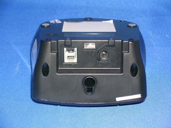
NC8P9122G
May 16, 2007900MHz 40Ch Analog Modulation Cordless Phonew/CID
Equipment Class
DXT - Part 15 Low Power Transceiver, Rx Verified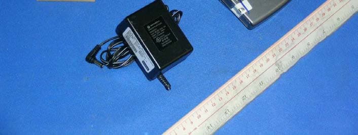
NC8SD7505
Sep 12, 20065.8GHz FHSS CellDock w/ Bluetooth
Equipment Class
DXT - Part 15 Low Power Transceiver, Rx Verified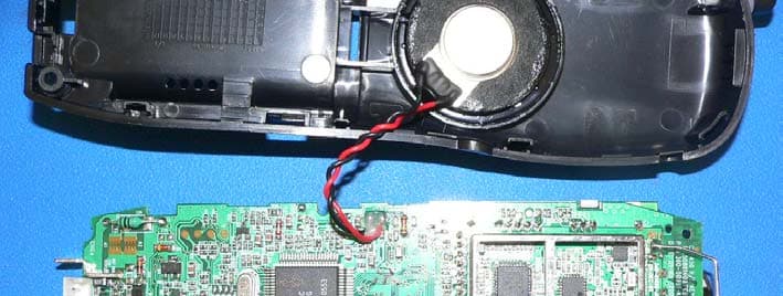
NC8CT5450
Aug 14, 20065.8GHz Cordless Phone
Equipment Class
DSS - Part 15 Spread Spectrum Transmitter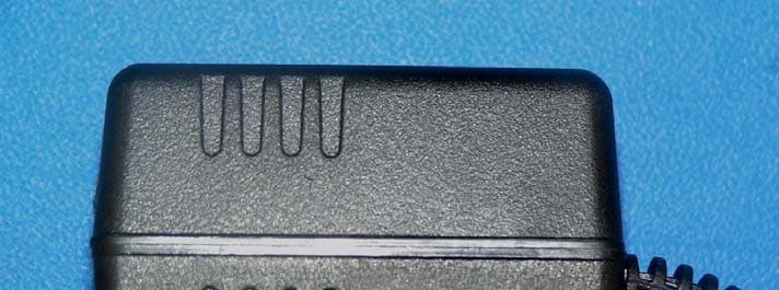
NC8MD2400
Jun 11, 20062.4Gz Cordless Phone
Equipment Class
DSS - Part 15 Spread Spectrum Transmitter
NC8KX-TG2120
May 24, 20062.4GHz/900MHz Analog Cordless phone w/ CID (Base)
Equipment Class
DXT - Part 15 Low Power Transceiver, Rx Verified